
Abstract
There are few studies on the lateral motion of spherical robots. In this article, a new algorithm is proposed to solve the problem of low control accuracy of the lateral motion. A single lateral motion model is established, and the optimal solution of the linear quadratic regulator in infinite time domain is obtained. Aiming at the problems of longitudinal velocity and lateral angle coupling and low control precision, state compensation and velocity feedforward are carried out, and an improved robust servo linear quadratic regulator control algorithm is proposed. Experiments show that the proposed lateral control algorithm has strong adaptability and robustness to changing speeds and lateral angles, and the control effect is stable and reliable.
Introduction
In recent years, with the development of the field of robotics, all kinds of robots play an important role in industrial, agricultural, medical applications, and other fields. 1 Spherical robot is a new type of mobile robot. Different from wheeled or footed robots, the closed spherical shell makes the robot not have the risk of overturning, and it is also more friendly to the sensors on board. 2 With the deepening of its research, spherical robots are gradually applied in the fields of security, patrol, detection, and inspection operations. According to the different propulsion mechanisms, spherical mobile robots (SMRs) are mainly divided into wheel-based SMR, 3 angular momentum-based SMR, 4,5 pendulum-based SMR, 6 centroid shift-based SMR, 7 wind-based SMR, 8 and deformable SMR. 9 The pendulum-based spherical robot studied in this article is a typical nonholonomic, nonlinear, and underactuated system, which also brings great challenges to the control of SMR.
Most studies on SMRs focus on trajectory following, and less on its motion control. 10 –13 For the motion control of SMRs, it is often decoupled into longitudinal control and lateral control. As the most widely used controller in the industry, the proportional–integral–derivative (PID) controller is also used in the control of SMRs and has achieved certain results. Although the PID controller does not require model-based operation, there are problems such as excessive overshoot or long adjustment time in the control effect. 14,15 Liu et al. achieved acceptable results for a range of speeds in longitudinal control using linear quadratic regulator (LQR). 16 The sliding mode control is also used in the control of SMRs this year, but its free-chattering problem has great harm to the actuator. 17 Ayati et al. proposed a hierarchical sliding mode controller, 18,19 but it requires a trade-off between chattering and robustness. 20 Because fuzzy control does not need the model of the object, it is often combined with other controllers to form a control algorithm with better robustness, but it has the problem of low control accuracy. 21,22 Most of the above control algorithms focus on the discussion of longitudinal motion control of spherical robots. Due to the complexity of the model, the lateral motion control and the longitudinal velocity are coupled with each other, and most researchers still focus on the simulation discussion. In practice, the lateral control algorithm is still dominated by PID.
LQR is a common method for designing optimal full-state feedback controllers for linear or linearized systems. LQR has been widely used in self-balancing unicycle robots, 23,24 multi-stage inverted pendulums, 25 drones, 26 legged robots, 27 and other fields. 28 –30 This article proposes a robust servo lateral motion controller for SMRs based on LQR. Firstly, a decoupled spherical robot lateral motion dynamic model is established and linearized, and the LQR method is used to solve the optimal control solution in the infinite time domain. Aiming at the problem of low control accuracy caused by linearization, state compensation is carried out, and velocity feedforward is used to solve the coupling problem of lateral motion and longitudinal motion. Finally, an integral term is added to improve the robustness of the controller. In order to verify the robustness and adaptability of the algorithm, a series of physical experiments rather than simulation experiments were designed and implemented.
The article is organized as follows: the second section establishes an independent spherical robot lateral model. The third section linearizes the established model and proposes a robust servo LQR (RSLQR) controller based on state compensation and velocity feedforward for lateral control of the spherical robot. The fourth section illustrates the experimental background and configuration. In the fifth section, practical experiments are carried out, the results are presented and compared with other controller. Finally, conclusions are given in the last section.
System description and modeling
The spherical rolling robot shown in Figure 1 studied in this article is based on a pendulum. The frame is equipped with the communication modules, microcontrollers, and other necessary modules. A pendulum with sufficient mass can swing freely in a space of two degrees of freedom. There is a motor on each of the longitudinal and lateral axes to drive the pendulum to swing. The output of the longitudinal axis motor makes the frame and the pendulum rotate around the longitudinal axis, which in turn causes the spherical robot to generate speed and start rolling. The output of the lateral axis motor makes the pendulum rotate around the lateral axis, causing the sphere to tilt, thereby changing the direction of movement of the robot. Figure 2 shows the motion process of the spherical robot. It is worth noting that the tilt of the sphere does not directly cause the robot to move laterally. The lateral motion of the robot is realized by the yaw angle changed by the tilt of the sphere during rolling, that is, this kind of spherical robot cannot turn in place. For the convenience of description, the symbols in Table 1 are used to represent the corresponding physical quantities. The spherical robot moves in a way similar to a car, the turning radius can be calculated by the following formula: Physical and simplified diagrams of the spherical robot. Simplified diagram of spherical robot motion: (a) Side view. (b) Front view. List of nomenclature.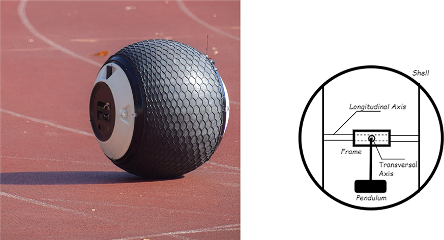


where r and qr represent the turning radius and the tilted angle of the spherical robot, respectively.
Therefore, the attitude control of the spherical robot is actually the control of its speed and turning radius which is achieved by changing the tilted angle qr of the robot.
Dynamic analysis and modeling
Dynamics of the proposed spherical robot is abstracted into two coupled differential equations in this article related to generalized coordinates (

where T and V represent the kinetic energy and gravitational potential energy of the system, respectively.
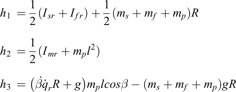
The spherical robot system is approximated into three parts (spherical shell, the frame, and the pendulum) shown as Figure 1, and their kinetic energy and gravitational potential energy are obtained respectively.
Spherical shell

The frame

The pendulum

The Lagrangian function of the overall system can be obtained from the above formulas

where
The generalized forces of the system are

Bringing equations (3) to (6) into equation (7), the following system dynamics model can be obtained

where

Linearization and state-space representation
The state-space form of a continuous linear time-invariant system is generally expressed as follows
where
Equation (8) can be expressed in the following form

where


In order to use a LQR, the system needs to be linearized first. Ignore the effect of higher order term

where

Let

Convert equation (11) to the standard state-space expression shown in equation (9), where

Now that the state-space representation of a SMR has been formulated, LQR can be employed to control the robot states and evaluate its performance.
Lateral motion controller of SMR
LQR controller
In practical applications, it is always desirable to control the system in this way: to make the system output as close to a desired output as possible. Let r denote the desired output, then

is called the error vector.
In robot lateral motion control, in addition to ensuring the optimal response of the system to the initial state in a limited time, the system also requires the ability to maintain a stable state. Such problems requiring both optimality and stability should be solved using infinite time regulator. Given the linear and time-invariant system with state-space dynamics in equation (9), the LQR formulation minimizes the following infinite quadratic cost function under dynamic constraints 9

where
where the matrices
For infinite-time state regulator, the endpoint index is usually not considered, and the weight matrix
if
For spherical robot,
9,12
the system is fully controllable because of the full rank of the array pair

Then there is a unique optimal control law for the system 31

where

For the actual spherical robot system, the control objective is that the error of tilt angle of the sphere is zero, so the control law can be expressed as follows

where
Robust servo LQR
The RSLQR optimal control method is developed on the basis of the traditional LQR control method. The idea of RSLQR is to introduce the integral link into the forward loop of the control law and define the state deviation as a new state vector. In this way, the adaptability of the controller to disturbances can be enhanced, so that the system has the ability to accurately track the input control commands. 32
Define a new state variable as

where


Then the performance index function of the new system of equation (20) is

The Riccati equation for the new system is

Get the control gain matrix shown below

Since

State compensation and velocity feedforward
In the second section, the effect of higher order term in the system is ignored for the convenience of linearization. The error model of the system can be expressed as

where
LQR will make

In order to make the error of the system approach

then

The solution of the problem can be equivalently expressed as follows: how to choose the value of
Let

then

In the spherical robot system of this article, the state compensation term takes the following value:

In addition, for the convenience of calculation and solution, the motion of the longitudinal axis and the lateral axis are considered to be completely decoupled when modeling. In fact, the tilted angle control of sphere is affected by the velocity. When the speed is higher, a larger centripetal force is required to achieve the same turning radius. Therefore, it is necessary to perform feedforward compensation according to the speed and the set angle. Experiments show that this compensation is a quadratic function of speed. Take the value of the following formula for velocity feedforward

where
IRSLQR controller
So far, the design of the overall control algorithm of the spherical robot has been completed. The schematic diagram of the improved robust servo LQR (IRSLQR) controller is shown in Figure 3. The control output of the algorithm consists of the following parts: the calculated torque of RSLQR, state compensation, and speed feedforward compensation, as shown in the following formula, Schematic diagram of the control system.

Stability analysis
For the stability research of the control system, Lyapunov stability theory is often used for analysis.
Define the Lyapunov function as follows

where

Then, take the derivative of

According to the system equation and control law, the following formula is obtained

Bring the feedback matrix calculated by RSLQR into the calculation

From the aforementioned Riccati equation, it can be known that

Substituting equation (6) into equation (5)

In the above formula,
Experimental setup
All the following experiments are based on the actual spherical robot with a diameter of 60 cm shown in Figure 1. The longitudinal and lateral motor torques are used to control the robot’s speed and lateral angle, respectively, which are the core principles of the robot’s operation. The measurement system consists of three sensors: two motor encoders for feedback of parameters such as torques and positions of the motors; a three-axis inertial measurement unit (IMU) for obtaining the real-time states of the robot (including acceleration, Euler angle, etc.) with Kalman filter and data fusion. Drapikowski et al. demonstrated that such a measurement system is sufficient for robotics. 33 The low-level control algorithm of the robot is implemented in a high-performance embedded system with C language, the sampling frequency is 100 Hz, and the control frequency is 50 Hz. Data transmission, Data recording, mapping, and navigation algorithm are implemented in the ROS middleware of the host computer.
Experimental results
This section provides experimental results of direct application of LQR to the spherical robot. The section also includes the implementation details and quantitative results of the IRSLQR controller and fuzzy PID (FPID) controller, and compares the performance of the two controllers.
LQR controller
In the previous control theory analysis, the system was linearized around the origin far away from the control boundary, and the LQR gain obtained by the linear system analysis. Note that the dynamic analysis of the system assumes that the motion speed and lateral motion of the robot are completely decoupled, which is not possible in real physical systems. In fact, the moving speed of the spherical robot is higher, the coupling between the speed and the tilted angle of the spherical robot is larger.
Figure 4 shows the results of controlling the robot using LQR alone. The shaded part in pink in the figure represents the difference between the actual tilted angle and the expected tilted angle of the robot. The red line represents the expected tilted angle of the sphere. Since the oscillation period of the spherical robot is uncertain, in order to better calculate the stabilized spherical robot tilted angle and verify the effectiveness of the controller, a filter with a constantly increasing time window is employed to smooth the tilted angle data and the results were represented by the blue line. Figure 4(a) shows the performance of the LQR controller when the robot was running at 0.5 m/s and the expected tilted angle was 0.105 rad. The actual tilted angle of the robot fluctuated around the expected angle because the point at which the system is linearized is the equilibrium origin (0 rad). At the same time, it is assumed that the motions in the longitudinal axis and lateral axis directions are decoupled during modeling, that is, the velocity and the tilted angle do not affect each other. Therefore, when the expected titled angle is larger and the speed is faster, the performance of the LQR controller is worse. Figure 4 supports this view.

The robot ran at 0.5 m/s for (a) and (b), 1.0 m/s for (c) and (d). (a) Expected angle: 0.105 rad. (b) Expected angle: 0.192 rad. (c) Expected angle: 0.105 rad. (d) Expected angle: 0.192 rad.
In order to qualitatively describe the experimental results, the maximum offset and the root mean square error (RMSE) are used. Among them, the maximum positive/minimum negative offset represents the maximum positive/minimum negative value of the actual tilted angle deviating from the expected angle within the time from the first time the spherical robot reaches the desired angle to the end of the experiment. RMSE measures the deviation between the observed value and the expected value. When the robot moved at a low speed of 0.5 m/s and the desired angle was 0.105 rad, RMSE is 0.0610 rad, the maximum positive offset is 0.096 rad, and the minimum negative offset is −0.134 rad. When only increasing the desired angle (0.192 rad), RMSE increases to 0.1006 rad, the maximum positive offset is 0.028 rad, and the minimum negative offset is −0.196. When only increasing the speed (1.0 m/s), RMSE increases to 0.0743 rad, the maximum positive offset is 0.013 rad, and the minimum negative offset is −0.136 rad. Increasing the speed to 1.0 m/s, while increasing the desired angle to 0.192 rad, results in an increase in RMSE to 0.1348 rad with a maximum positive offset of 0 rad and a minimum negative offset of −0.237 rad. It can be seen that the control performance of pure LQR drops sharply when the speed and desired angle are far from the linearized equilibrium origin.
IRSLQR controller
Aiming at the problems of poor robustness and large steady-state error of LQR controller, an IRSLQR controller is proposed in this article, as shown in Figure 3. To verify the effectiveness and robustness of the proposed controller, different tests are designed to conduct experiments, and its performance is compared with the FPID controller proposed in the previous paper. 34 For a strict comparison between the model-based controller (IRSLQR) and the error-based controller (FPID), experiments were conducted on the spherical robot repetitively and analyzed with representative values.
Single-angle tracking experiment at a single speed
The first test involved of the experiments is the tracking performance of the two controllers at different speeds for angles. Due to the limitation of the mechanical structure of the spherical robot and the centrifugal force, when the speed of the robot is higher than 1.3 m/s, the tilted angle can no longer reach 0.192 rad. Therefore, in the test, three speeds of 0.5 m/s, 1.0 m/s, 1.3 m/s and two desired tilted angles of 0.105 rad and 0.192 rad were set to verify the effectiveness of the proposed controller. Under the two controllers, the robot independently tracked different desired angles based on different speeds. Figure 5 shows the experimental results. The pink shaded part and the yellow shaded part in the figures represent the difference between the actual tilted angle and the expected tilted angle of the spherical robot controlled by IRSLQR and FPID controller, respectively. The red line represents the expected tilted angle, and the blue and green lines are the actual tilted angle data obtained by smooth filtering of the IRSLQR and FPID controller, respectively. In this section, in addition to the RMSE and maximum offset mentioned above, the minimum steady-state error (MSSE) is also used to characterize the control effect. MSSE is defined as the minimum error after the system enters the steady state during the entire control process, which is reflected in the minimum deviation between the blue line/green line and the red line in Figure 5. Table 2 shows all the performance indicators of the two controllers. It can be seen from the experimental results that the RMSE of IRSLQR is about half smaller than that of the FPID controller, and the MSSE is an order of magnitude smaller, regardless of high speed or low speed, large angle or small angle. The maximum offset distribution of IRSLQR is relatively uniform, and the absolute value is less than 0.0785 rad. With the increase of speed and angle, the maximum positive offset of the FPID controller gradually decreases, and the minimum negative error gradually increases. It may not even reach the expected angle. The control accuracy of the proposed controller is higher than that of FPID, and the robustness and adaptability are also better.

The robot ran at 0.5 m/s for (a) and (b), 1.0 m/s for (c) and (d), 1.3 m/s for (e) and (f). (a) Expected angle: 0.105 rad. (b) Expected angle: 0.192 rad. (c) Expected angle: 0.105 rad. (d) Expected angle: 0.192 rad. (e) Expected angle: 0.105 rad. (f) Expected angle: 0.192 rad.
The experimental results comparison of the two controllers.

PID: proportional–integral–derivative; IRSLQR: improved robust servo linear quadratic regulator.
Single-angle tracking experiment with variable speed
To further verify the robustness of the proposed controller with respect to the spherical robot velocity, the desired velocity profile was designed in stages while keeping the expected angle constant. The experimental result is shown in Figure 6. The black line corresponds to the ordinate on the right, representing the variation law of the velocity in the whole process. The shades of blue and green represent the difference between the expected tilted angle (red line) and the actual tilted angle of the spherical robot, respectively. IRSLQR has a RMSE of 0.0344 rad, a maximum positive offset of 0.0558 rad, and a minimum negative offset of −0.0839 rad, while FPID has a RMSE of 0.0594 rad, a maximum positive offset of 0.1105 rad, and a minimum negative offset of −0.1546 rad. The velocity change will not have much influence on the control effect of IRSLQR, and its robustness to speed is better than that of FPID.
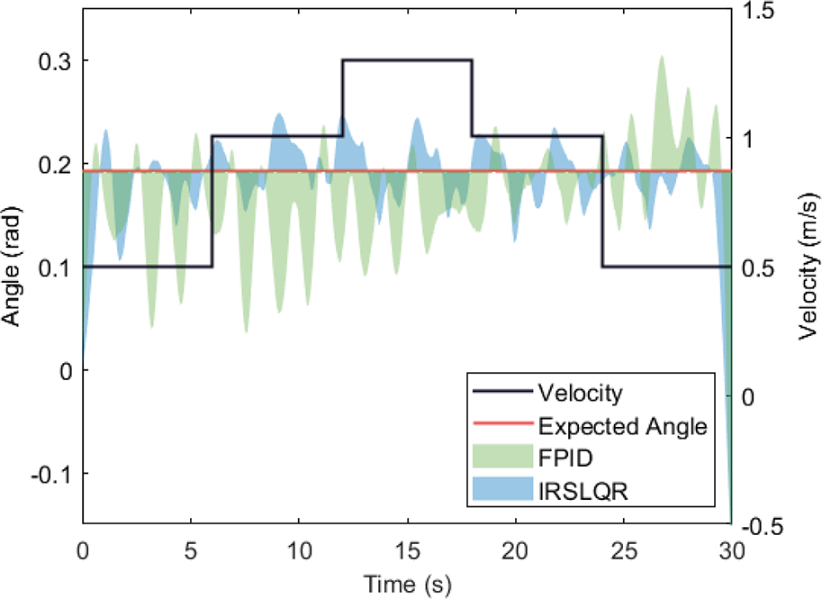
Controllers response at continuously changing speed.
Variable-angle tracking experiment with single speed
In practical application scenarios, the expected tilted angles are usually varied. The experiment continuously changed the desired tilted angle within 30s to test the response performance of the two controllers. Throughout the experiment, RMSE of IRSLQR is 0.0325 rad, the maximum positive offset is 0.0610 rad, the minimum negative offset is −0.0917 rad, and RMSE of FPID is 0.0505 rad, the maximum positive offset is 0.1040 rad, and the minimum negative offset is −0.1080 rad. The performance of both controllers degraded for a period of time after the desired angle change. Compared to FPID, IRSLQR could adjust faster and stabilize the angle around the desired angle again. It can be seen from the experimental results that the robustness and adaptability of the proposed controller to the angle is better than that of FPID.

Controllers response at continuously changing expected angles.
Conclusion
In this study, we focus on lateral motion control of the spherical robot. To this end, a spherical robot lateral dynamics equation decoupled from the velocity is proposed, and linearized at the equilibrium point, and the corresponding optimal controller (LQR controller) is designed according to the linearized equation. However, only using the LQR controller designed after linearization will have steady-state errors and its control accuracy is not enough. Therefore, we propose an IRSLQR controller based on state feedback and speed feedforward, which has high robustness and strong adaptability.
To verify the performance of the proposed controller, we designed and conducted various experiments and compared the experimental results with the FPID controller. The experimental results show that the IRSLQR controller has better performance both in control accuracy and speed/angle robustness. This indicates that the proposed controller has broader application prospects in practical scenarios.
However, the lateral motion of spherical robots still has many challenges. For example, in unknown terrain environments, the established model can no longer be applied, so new algorithms are required for the stable control of the angle. In addition, stable control on a sloped road is also a challenging problem. We will then focus on related topics for research.
Footnotes
Declaration of conflicting interests
The author(s) declared no potential conflicts of interest with respect to the research, authorship, and/or publication of this article.
Funding
The author(s) received financial support for the research, authorship, and/or publication of this article: This work was supported by the National Key Research and Development Program of China (No. SQ2019YFB130016) and the Fundamental Research Funds for the Central Universities (226-2022-00086).