
Abstract
Fish is the master of fluid control, with high propulsive efficiency and great maneuverability. Carps are chosen for observations since they are the typical carangiform fish. We add some external stimuli on the fish and observe their responses. It is found that a fish attempts to escape backward or forward depending on the stimuli. The fish tries a greater number of its tail oscillations in a forward escape than in a backward escape. In the case of a forward escape, the retract stroke where the tail gets a concave shape (suitable for higher thrust generation) is faster than the forward stroke where the tail takes a convex shape (suitable for smaller drag), while vice versa in the case of a backward escape. Becoming concave or convex shapes of the tail and being faster or slower strokes all correspond to enhancing fluid momentum in the forward or backward directions where appropriate. The traveling wave of the body propagates backward and forward for the forward and backward escapes, respectively. The results provide a reference for bionic fish design and simulation.
Introduction
Fishes are the principal habitant in the ocean and a well-deserved master of flow control. In a long period of adaptation and evolution, fishes and birds have achieved excellent propulsion performance with fast speed, high efficiency, and great maneuverability. 1 –3 A fish having body motion transports the fluid from the head to the tail and creates a reversed Karman vortex street in the wake, which leads to the generation of propulsive thrust. Based on the generation mechanism of thrust, the fish locomotion is classified into two modes. 4 One is called the body and/or caudal fin (BCF) locomotion, where a fish generates thrust by bending its body and forming a traveling wave propagating toward the caudal fin. The other one is median and/or paired fin locomotion, where the median and pectoral fins are used to generate thrust. The BCF mode is more common in nature and adopted by most fishes. Here, we focus on the BCF locomotion. Lindsey 5 classified the BCF locomotion into five modes (anguilliform, subcarangiform, carangiform, thunniform, and ostraciiform) based on the differences in the wavelengths, the amplitude envelopes, and the ways how thrust is generated.
The fish locomotion is such effective that the propulsive efficiency of fish is higher than that of traditional underwater vehicles. Many experimental investigations have been carried out on fishes to understand how the fishes generate efficient locomotion. To investigate the dependence of locomotion speed on the frequency and amplitude of the fishtail, Bainbridge
6
devised an apparatus called “fish wheel” that could rotate in the horizontal plane. Based on the results of all sizes and species recorded, he established a formula
Archer and Johnston
8
investigated the kinematics of subcarangiform swimming of the Antarctic fish Notothenia neglecta. Fish were trained to swim along a 4-m long raceway. With an association of a background illumination lighting system and reflex reflector material, cameras were able to capture dark silhouettes of the fish against a bright background from the dorsal and side. Results showed that juvenile fish are capable of higher length-specific forward speeds because of their faster tail-beat frequencies and shorter body lengths. Xiong and Lauder
9
used an image cross-correlation technique to study the center of mass oscillation and tail beats of knifefish, sunfish, and eels. They revealed that the amplitude of the tail beat did not increase significantly with increasing speed while the tail-beat frequency had a significant impact on swimming speed for all the species. An increase in the frequency led to a higher swimming speed as the thrust increases with the cube of the frequency.
10,11
Dewar and Graham
12
measured the metabolic rates (
Cui et al. 13 used a method of complex orthogonal decomposition to decompose the midline motions of swimming fish and calculated the traveling index, which was defined as the relative ratio between the magnitudes of the traveling and standing components. Their numerical results showed that carangiform fish swim efficiently when the traveling index is around 0.6, which agreed well with the experimental results and explained why the fish choose this pattern of body locomotion. Müller et al. 14 applied two-dimensional particle image velocimetry to investigate the wake structure of a swimming mullet. Two start–stop vortices were shed during one tail-beat cycle. The hydrodynamic efficiency derived from the wake vortices appeared to be greater than 90%, which indicates that the motion and wake are interconnected. Drucker and Lauder 15 used digital particle image velocimetry (DPIV) to visualize water flow in the wake of the pectoral fins of swimming bluegill sunfish. Using 3D synthetic aperture PIV, Mendelson and Techet 16 quantitatively analyzed the three-dimensional wake behind a giant danio during cruising and turning.
Attracted by the excellent propulsion performance of fish, many fish-like robots have been designed based on the observed swimming parameters and patterns. 17 –24 However, the propulsive efficiencies of all kinds of robotic fish are still far lower than those of real fish. 10,25 This may be due to the fact that robot fish have rigid tails, and the pitching motion is sinusoidal. The tail motion and flexibility of a robotic fish are perhaps far from a real fish. It suggests that more investigations are needed on the behaviors of fish during swimming.
A fast start, having burst accelerations, is required when a prey wants to escape from a predator. 26,27 Swimming of fish is of three major types. 28 The first type is sustained swimming with a swimming duration longer than 200 min. It is largely steady propulsion, with periodic body movement. The second type is prolonged swimming varying from 20s to 200 min, combining steady and unsteady propulsion. The third type is the burst that persists for less than 20s. The fast start is the early stage of the burst, lasting for less than 1s. The fast start is unsteady and transient. Both prey and predator require fast starts. Naturally, they follow distinct types of starts: C-starts by preys and S-starts by predators. 11,29 These fast starts have three kinematic stages: stage 1 is the preparatory stroke to form a C-shape, stage 2 is the propulsive stroke generating a high acceleration, and stage 3 is variable, involving continuous swimming or coasting. 30
The use of hydrofoil has been the most pervasive method to understand the hydrodynamic performance of the caudal fin. The hydrofoil is rigid, hence does not change its shape during the oscillation. In addition, the hydrofoil is generally given sinusoidal, symmetric pitching and/or heaving motion. Both model and motion are too simplistic as the tail of a real fish changes its shape during its oscillation, and the motion may not be symmetric but differ from one stroke to another. For an efficient design and simulation of bionic fish, a couple of questions are required to pay attention to. For example, is the motion symmetric about the propulsion axis? Is the time required for the forward and retract strokes the same? What are the differences in tail motion between the forward and backward propulsions? How does the tail shape modify during the tail oscillation? The answers to these questions are required for the efficient design and simulation of bionic fish. This work aims to examine the psychology, behavior, and dynamics of fish subjected to different external stimuli, like holding fish in an experimental setup or in the hands. Further attention is paid to investigating how the tail motion and shape change during tail oscillation in the cases of forward and backward propulsion.
Experiment setup and method
Carps, typical carangiform swimmers and the most common economic and ornamental fish in China, were chosen for the investigation. A dozen of similar-sized carps were collected from a local pet shop. Before the experiment, the lengths of the fish were measured by holding and placing them along a ruler, as shown in Figure 1. The lengths of the carps were 164 ± 5 mm. Experiments were conducted in a water tank with dimensions 1200 mm in length, 600 mm in width, and 500 mm in height. The tank was filled with freshwater of 25 ± 1°C to a level of 400 mm. A Basler acA2500-60um Mono camera (maximum frame rate up to 800 fps), mounted with Sigma 35 mm 1.4 DG HSM lens, was used to capture the images. A rectangular flat mirror (600 mm × 300 mm) was placed under the fish, inclined 45° with the horizontal plane, to reflect the abdomen image of the fish (Figure 2).

Fish anatomy and length measurement.

(a) Fish holding device, (b) sketch of the setup, and (c) picture of the overall setup in water tank. The swimming of the motion was restricted in single-degree of freedom as shown in figure (a). A “T-shaped” arm with load cell was used to measure the thrust by fish. To avoid the refraction of the uneven water surface, a mirror was placed below the fish, inclined 45° with the horizontal plane. A camera was put at the same height as the mirror.
In order to observe the response of fish under external stimuli, a set of fish-holding devices were designed and fabricated. It is worth mentioning that these devices were originally designed to hold the fish and measure its thrust during the forward propulsion (Figure 2). A three-axis load cell (model: 3A60-20N-D11) from Interface was used to measure the thrust of fish. The capacities of the load cell were 20 N in all three directions. A “T-shaped” arm (450 mm long and 20 mm × 20 mm in cross-section) was designed to support the fish and the load cell (Figure 2(a)). Here, we will introduce the fish-holding components of this setup.
The holding component in Figure 3(a) consists of two curved frames (upper, lower) and two rubber bands to fasten a fish. The upper frame is designed to fit the carp’s dorsal shape, with a contact area of about 50 mm × 60 mm, and a radius of curvature varying from 15 mm to 20 mm. The lower frame is designed to fit the carp’s belly size, with a contact area of about 60 mm × 100 mm. The diameters of the rubber bands are 2 mm. The rubber bands can tighten the fish as much as we want, by adjusting snap joints mounted at each end of the rubber bands. These rubber bands and the two frames were, however, not enough as the fish will get hurt from the two frames and also from the rubber bands. We, therefore, placed two blocks of sponges to protect the fish from getting hurt (Figure 3(b1) and (b2)); it is herein referred to as stimulus 1. The sponge blocks are of size around 65 mm × 20 mm × 10 mm.

Holding components to add the external stimuli on fish. (a) Sketch of the empty holding device. (b1, b2) Stimulus 1: different views of holding device with sponge placed. (b3) Fish is held with stimulus 1. The black rubber bands are used to fasten and tighten the fish. (c1–c4) Stimulus 2: (c1, c2) lower frame removed; (c3, c4) fish is tied up with a hook and loop belt. (d1, d2) Stimulus 3: different views of holding device with sponge inside and mosquito nets outside. This device can hold the fish head with eyes capped. (e1, e2) Stimulus 4: tying up the pectoral fins of the fish with thread.
Next, the lower frame was removed but we kept the upper frame and sponges (Figure 3(c1) and (c2)). Removing the sponges and rubber bands, we also tried using a hook and loop belt to fasten the fish (Figure 3(c3) and (c4)). Here, we call this system as stimulus 2. Later, we capped the fish’s eyes and head, using mosquito nets and sponges (Figure 3(d1) and (d2), stimulus 3). Finally, we removed the holding device (lower and upper frames, sponges, rubber bands). A thread was used to tie up the pectoral fins of fish, with the two ends of the thread (Figure 3(e1) and (e2)). The middle of the thread was connected to the T-shaped arm to observe swimming and measure forces. This is referred to as stimulus 4.
The fishes were in another water tank before they are held and put in the test tank. They were healthy and lively. The experiments were done for 12 fishes, each provided qualitatively similar results, although quantitative displacement of the peduncle differs between experiments. The strength of holding the fish with hands each time was naturally different but the physical locomotion strategy was the same.
Response of fish under external stimuli
Response under stimulus 1: When fixed with the device in Figure 3((b1) to (b3)), the fish struggled irregularly, largely trying to escape forward. It also tried to escape backward after several forward tries. Generally, the duration of a try was longer for a forward escape than for a backward escape, about two to four oscillations of the tail for the former and less than one oscillation for the latter. It came out that fish escapes or tries to escape when it is held not tight enough, but it tends to stay calm for a long time when it is held very tight.
Response under stimulus 2: When fixed with the holding components in Figure 3(c1) and (c2), the fish can still escape forward after several tries because of its slippery body surrounded by the sponge (see Figure 4). The fish pushed itself forward using its tail oscillation (Figure 4(a) and (b)) and finally escaped forward (Figure 4(c)). The fish fastened with hook and loop belt was more vibrant to escape forward or backward (Figure 3(c3) and (c4)), because the width of the belt was smaller than the width of the sponge. When the belt was between the head and pectoral fins (Figure 3(c3)), the fish tried to escape backward. On the other hand, it tried to escape forward when the belt was on or beyond the pectoral fins (Figure 3(c4)).

Carp escaped from the holding component when it was held not tight enough. (a) Carp was held by the device; (b) carp started to struggle and moved forward through sponge; finally (c) it successfully escape forward from the device.
Response under stimulus 3: In order to restrict the forward escape, a mosquito net was used to cap the head, as shown in Figure 3(d1) and (d2). The fish realized that it could not get away from the front, so it always tried to move backward using its caudal fin only. This backward movement was not investigated in the literature, and it will be further discussed later.
Response under stimulus 4: Although the introduction of the thread seems to add little influence on the swimming movement of the fish, the thread restricted the movement of the anterior part of the body and made it swim unnaturally.
Tail shape and motion for forward propulsion
The oscillation of the caudal fin on numerical simulations is considered as sinusoidal, where the maximum transverse velocity of the fin occurs when the caudal peduncle is straight, lying along the axis of progression. A simple model of fish midline motions, frequently used in the modeling of computational swimming fish, is expressed as 31,32

where
In reality, it is an irregular sine wave and differs for different species. 33 For the bream, the maximum transverse velocity was attained about midway between the lateral extreme and the axis of progression. For the dace, the maximum velocity was at the axis of progression. Fierstine and Walters 7 noted that the five specimens of wavy-back skipjack have the highest transverse caudal velocity near or past the axis of progression.
To observe the forward and backward propulsions of a carangiform swimmer, a carp was held in hands and its movements were recorded by a high-speed video camera. The hands can easily sense the forward or backward movement of the fish. When the head of the fish was held little softly, the fish tried to escape forward, that is, trying to have forward propulsion. The caudal peduncle oscillation was about two cycles. The snapshots in one complete oscillation of the caudal fin in the case of the forward escape are shown in Figure 5. Through the superposition of snapshots corresponding to the caudal fin at the two extreme lateral positions (Figure 5(m)), the central line (blue line) is determined. Blue dots represent the base of the caudal fin, that is, the junction between the caudal peduncle and caudal fin. At time t = 0 where the peduncle is on the left side (Figure 5(a)), the caudal fin tends to return toward the centerline, the peduncle having one bend. From t = 0 to 0.94 s, several interesting observations can be made. Firstly, another bend is generated on the upper part of the peduncle and propagates toward the caudal fin. Secondly, the caudal fin travels from the left side to the right. Thirdly, the first bend also moves toward the caudal fin that gets a C-shape at t = 0.94–1.05 s. This formation of the C-shape at the extreme position is auspicious for pushing fluid backward when the caudal fin tends to return toward the centerline. Fourthly, the time required for the fin base (blue dot) to move from its extreme position (t = 0) to the centerline position (t = 0.28 s) is 0.28 s while that from the centerline position (t = 0.28 s) to the extreme (t = 0.94 s) is 0.77 s, the latter being 2.35 times larger than the former. Similar observations are made in the next half cycle (t = 0.94–1.23 s) although the magnitude of the maximum amplitude differs between the first- and second-half cycles. It suggests that the duration of the retract stroke is shorter than the forward stroke. Here, the retract stroke is defined as the movement of the blue dot from its extreme to the centerline while the forward stroke is the movement of the same from the centerline to its extreme. 29,34,35

(a–l) Forward propulsive pattern. (m) Superposition of snapshots at t = 0 and t = 2.3s in order to determine the central line.
By measuring the perpendicular distance between the fin base and the central line at different snapshots, the time history of the lateral position (in pixels) of the fin base is shown in Figure 6. Interestingly, the retract stroke differs from the forward stroke in a couple of aspects: (i) the duration of the retract stroke is shorter than that of the forward stroke, and (ii) the average velocity (slope) is higher in the retract stroke than in the forward stroke. Muhammad et al. 29 conducted numerical simulations of a rigid hydrofoil undergoing a pitching motion where the retract stroke was systematically varied to make the time duration shorter or longer than the forward stroke. They found that thrust and efficiency both dramatically enhance when the retract stroke was made shorter, and vice versa. They further proposed that the faster retract stroke may be the fast start of prey to escape from a predator. On the other hand, the faster forward stroke may provide braking to the propulsion. Their rigid hydrofoil results bear consistencies with the present live-fish results.

Time history of the lateral position of the peduncle in forward propulsive pattern. Distances are measured as the perpendicular distances between the peduncle and the central line.
Tail shape and motion for backward propulsion
The fish tried to have backward propulsion when the fish head was held little tightly. The oscillation of the peduncle for the backward propulsion was less than one cycle once it felt that it could not escape. Snapshots of the fish kinematics for backward propulsion are presented in Figure 7 for a half cycle. At time t = 0, the peduncle is of a C-shape, most bent, having a high curvature. It is thus assumed as the end of the forward stroke and the start of the retract stroke. From t = 0.39 s to 1.06 s, the peduncle takes an S-shape. On the other hand, at t = 2.07 s to 2.47 s, the peduncle gets a flipped C-shape, with the peduncle fin lying on the left side. The peduncle is extremely bent at t = 2.17 s, the end of the forward stroke. The trajectory of the junction point (blue dot) between the peduncle and the fin is presented in Figure 8. Interestingly, the retract stroke is very slow, taking a long time to reach the centerline while the forward stroke is very fast, taking a short time to travel from the centerline to the extreme position. This observation is opposite to that in the case of the forward propulsion.

(a–g) Backward propulsive patterns for a half cycle of the peduncle from the right to the left. (h) Superposition of snapshots at t = 0 and t = 2.47 s in order to determine the central line.

Time history of the lateral position of the peduncle for backward propulsion, with the peduncle fin moving from the left to the right. Distances are measured as the perpendicular distances between the peduncle and the central line.
Figure 9 displays snapshots for another half cycle. Similar observations are made, including a C-shape at the extreme positions and an S-shape between the extremities. Here, the amplitude of oscillation is larger than that in Figure 8. Figure 10 again shows that the forward stroke is faster, taking a shorter time, than the retract stroke.

(a–g) Backward propulsive patterns for a half cycle of the peduncle from the left to the right. (h) Superposition of figure at t = 0 and t = 0.27 s in order to determine the central line.

Time histories of the lateral position of the peduncle for backward propulsion, with the peduncle fin moving from the right to the left. Distances are measured as the perpendicular distances between the peduncle and the central line.
Underlying features of forward and backward propulsion
The above observations on the forward and backward propulsion can be schematically illustrated in Figure 11. The basic principle of generating forward thrust is producing fluid momentum toward the backward direction; the higher the backward fluid momentum, the greater the forward thrust. On the other hand, the peduncle and the fin should generate fluid momentum in the forward direction to generate the backward thrust that is required for backward propulsion.
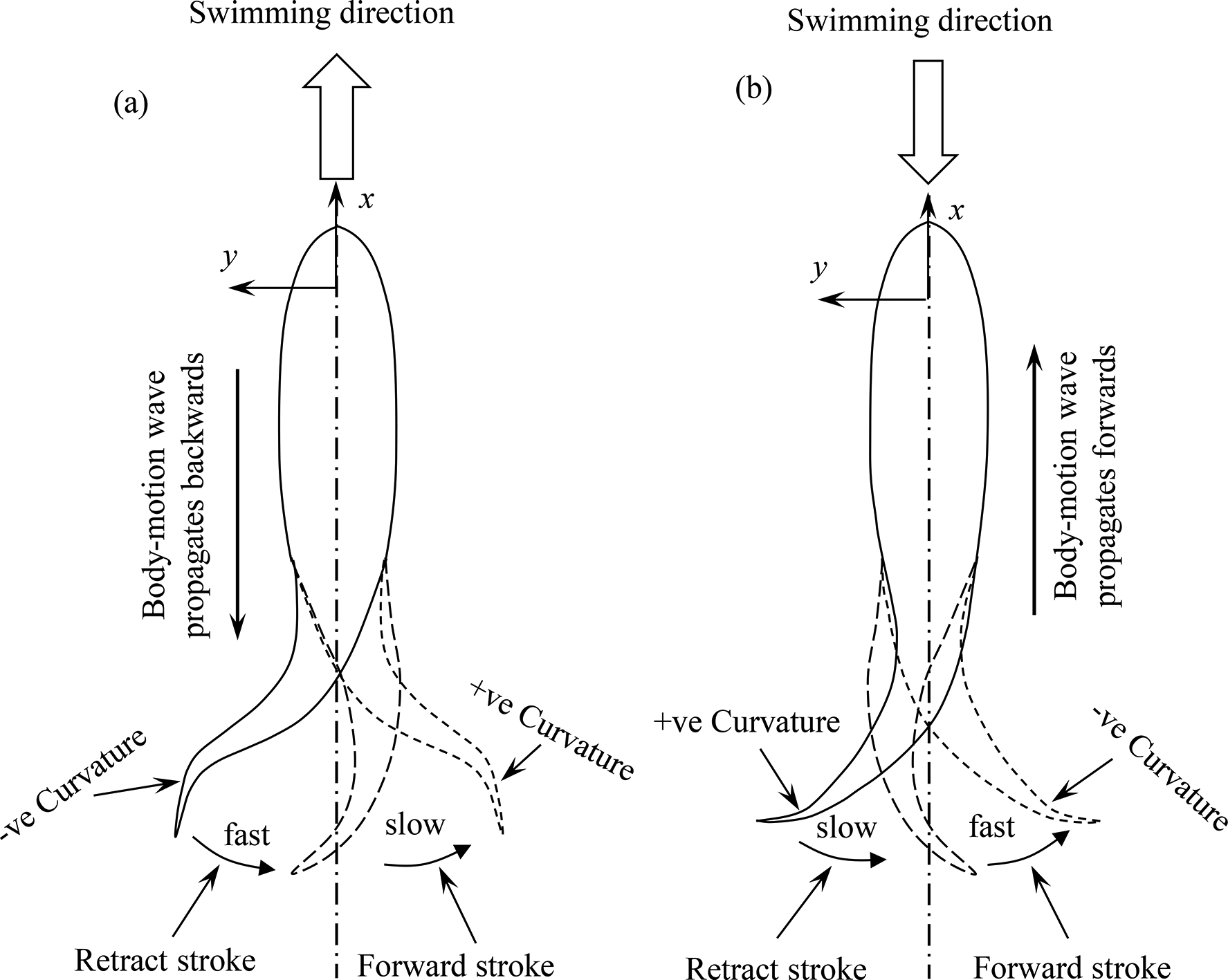
Sketches showing mechanisms of (a) forward propulsion and (b) backward propulsion of fish.
In the case of the forward propulsive motion (Figure 11(a)), the following features can be highlighted. The average lateral speed of the peduncle or fin is larger in the retract stroke than in the forward stroke. In other words, the retract stroke is faster than the forward stroke. This makes a higher thrust in the retract stroke, pushing fluid backward at a higher speed or higher momentum. 29 The curvature of the tail is −ve (see x–y coordinate) in the retract stroke, such that the tail shape is auspicious to generate a larger backward momentum. On the other hand, the slower forward stroke is not auspicious to generate forward thrust as the tail essentially moves forward (with respect to the main body), restraining the backward fluid momentum. The motion in this stroke is thus kept slow, required to prepare the tail for the next retract stroke. The curvature of the tail shape in this stroke is +ve, opposite to that in the retract stroke. This +ve curvature makes the tail easy to move forward, with less power input. The traveling wave of the body propagates backward. This backward propagation of the traveling wave generates backward fluid momentum, pushing the fluid backward. It thus contributes to the forward thrust.
Figure 12 shows a time history of thrust and changes in fish body shape during a forward escape. The fish made its forward escape when the belt was on the pectoral fins (Figure 12(b)). As expected, thrust fluctuates about zero up to 5.7 s, followed by two positive surges at 5.8 s and 6.7 s, respectively. The surge at 6.7s springs from a strong oscillation of the caudal peduncle (Figure 12(c)). Very large thrust (strongest surge with two peaks in a short period) is generated to facilitate the forward escape, where the caudal peduncle has the strongest oscillation and the caudal fin produces positive curvature to enhance thrust (Figures 11(a) and 12(d)). After the pectoral fins get out of the belt, the body in the belt bends and produces negative thrust to complete the forward escape (Figure 12(e)).

Load cell signal and fish movement captured simultaneously for forward escape.
For the backward propulsive motion (Figure 11(b)), the retract stroke is slower than the forward stroke, reciprocal to the counterparts in the forward propulsive motion. Here, the tail has a +ve curvature in the retract stroke and a −ve curvature in the forward stroke. Since now the fluid momentum should be in the forward direction to generate backward thrust, the −ve curvature in the forward stroke can generate more forward fluid momentum than the +ve curvature in the same stroke. The forward stroke is thus faster, and the tail shape has the −ve curvature. Oppositely, the retract stroke is slow as the tail motion tends to push fluid in the backward direction. The tail shape with the +ve curvature is auspicious to move toward the centerline. Here, the body traveling wave propagates forward to generate forward fluid momentum and contributes to the backward thrust.
Time histories of thrust and body shape changes during a backward escape are shown in Figure 13, where the belt was between the head and the pectoral fins (Figure 13(b)). The fish generates several surges in thrust before escaping at 1.55s where the thrust is negative as the caudal peduncle and fin take a shape that can push fluid forward (Figure 13(c)). Naturally, this shape with the negative thrust for the backward escape differs from that with the positive thrust for the forward escape (Figures 12(d) and 13(b)). As the head tappers off in a small segment, the fish immediately gets loose from the belt but several positive peaks in force are sensed by the load cell before the head gets out of the belt (Figure 13(c) and (d)). The positive peaks before the head out of the belt come from the impact of the strong forward momentum of fluid onto the support bar.

Load cell signal and fish movement captured simultaneously for backward escape.
Discussion
Fishes have brilliant propulsion performance with fast speed, high efficiency, and skillful maneuverability. It is found that there are two major factors involved in the kinematics of the tail. One is the oscillation trajectory of the tail, and the other is the tail shape modification during the oscillation. One should understand these two kinematic factors for a real fish and then implement the two kinematic factors in the design and simulation of bionic fish. The implementation of these kinematic features can make the bionic fish efficient in propulsion, agitation, and maneuverability. The present research on live fish reveals that the tail oscillation is not symmetric about the propulsion axis, but the retract stroke is faster than the forward stroke in the case of forward swimming, the average velocity being higher in the former stroke than in the latter. The tail shape appears concave and convex in the retract and forward strokes, respectively. The concave shape in the retract stroke is suitable for the thrust generation, producing a larger backward momentum, while the convex shape in the forward stroke reduces drag (−ve thrust), so that it is relatively easy for the tail to move from the centerline to the extreme. The forward stroke essentially prepares the tail to be a concave shape for the next retract stroke. The scenario is opposite for backward swimming, where the forward stroke is faster than the retract stroke, with concave and convex shapes of the tail, respectively. The average velocity is higher in the forward stroke than in the retract stroke.
Conclusions
In this study, the response of fish to external stimuli has been observed. Fish tries to escape when held not tight enough while it stays calm when held tight. It is found that a fish tries to escape forward for a longer time, about two to four oscillations of the tail. On the other hand, for a backward escape, it tries for a shorter time, less than one oscillation. For both forward and backward propulsion, the time duration differs between the retract and forward strokes.
For the forward propulsion, the retract stroke takes a shorter time than the forward stroke. In the retract, faster stroke, the tail takes a concave shape, suitable for higher thrust. On the other hand, in the forward, slower stroke, the tail is of a convex shape, suitable for smaller drag. The forward stroke is essentially a preparatory stage for the tail to take a concave shape for the next retract stroke. The traveling wave of the body propagates backward, contributing to the backward fluid momentum.
The scenario is opposite for the backward propulsion. The forward stroke is shorter than the forward stroke. The forward stroke corresponds to a concave shape of the tail, which is auspicious to generate more momentum in the forward direction. Since the retract stroke is now the preparatory stroke for the forward stroke, the tail uses a convex shape in the retract stroke. The traveling wave propagates from the fin to the body to generate forward fluid momentum. These results will be useful for bionic fish design and simulation.
Footnotes
Acknowledgment
The author wishes to acknowledge support given to them from NSFC through grant 11672096 and from the Khalifa University of Science and Technology through Grants CIRA-2020-057. The contributions of Li Chengji to the experiment and preparing some figures are gratefully acknowledged.
Declaration of conflicting interests
The author(s) declared no potential conflicts of interest with respect to the research, authorship, and/or publication of this article.
Funding
The author(s) received no financial support for the research, authorship, and/or publication of this article.