
Abstract
Stick–slip is a challenging problem in palletizing robots and constitutes one of the main problems in precision positioning control. This study analyzed the stick–slip of a four-degree-of-freedom ceiling-mounted hand-guiding collaborative robot in a working space. A brief perspective on the focus of the experimental design is presented on the stick–slip friction of a palletizing robot’s hand guidance as a collaborative robot. The palletizing robot typically has a simple mechanical structure but possesses over 16 bearings to constrain the motion of the dual-parallelogram linkage mechanism. First, the hand-guiding force was successfully measured. Second, an image model was built based on the obtained measurement results. Third, the stick–slip results for the working space were analyzed using an image model. Finally, related conclusions and recommendations are provided for precision positioning control. A significant aspect of this study is identifying the hand-guiding force in the working space of a ceiling-mounted collaborative robot. Stick–slip in hand guiding is a critical issue and is therefore important for collaborative robot users. The main contribution of this study is developing a feasible method for helping researchers understand where stick–slip occurs.
Keywords
Introduction
The collaborative robot (cobot) was invented in 1996 by J. Edward Colgate and Michael Peshkin. Cobots are generally used for automated applications with a recently increasing trend for industrial and service use in compliance with the industry 4.0 strategy. 1 A palletizing robot (i.e. a robot for placing and securing products on pallets) is usually an efficiently performing robot with many degrees of freedom. It constitutes an essential cobot, widely used in production lines. 2
Cobots are featured by removing safety barriers in their collaborative operation around humans.
3
The International Organization for Standardization (ISO) has published the ISO10218 and ISO/TS 15066 standards to regulate the framework of this operation. There are four types of collaborative operation
4
–7
: Safety-rated monitored stop: A stop is assured without power removal. Hand guiding: A manually controlled robot system. Speed and separation monitoring: The robot system speed is controlled based on the separation between it and any intrusion. Power and force limiting: The robot’s speed, torque, and motion are controlled to prevent the impact from causing injuries while operating automatically.
Here, we mainly focus on the type of combined operation, that is, hand guiding. It essentially consists of a manually controlled robot system in which the motion, at a stable speed, is critical for achieving precision positioning. Nonetheless, this operation engenders the most hazardous collision probability with the cobot due to inertia. 8 Several methods have been proposed in the literature to prevent danger in hand-guiding operation, including limiting the motion in the prescribed task region, 9 hand guiding a robot along a predefined geometric path, 10 measuring the transition of the impact force, 11 applying position follow-up control, 12 and using a passive protection device. 13 Here we address this problem from the perspective of the stick–slip phenomenon, which occurs during the cobot motion. For this, we used a four-degree-of-freedom (4-DOF) ceiling-mounted palletizing cobot. The stick–slip was measured and investigated to develop routes for solving the hazard problem in hand-guiding operation and improve the precision positioning control.
Stick (static) and slip (dynamic) frictions are qualitatively different and distinct phenomena. The stick–slip phenomenon is a sudden jerking motion that can occur while the palletizing robot is moving. Its unpredictable occurrence and uncontrolled action engender the cobot collision hazard. If the stick–slip motion can be measured accurately, it generally indicates that static friction is not purely so. 14
The importance of controlling the stick–slip of cobots has been underrated so far. Nonetheless, eliminating or reducing this phenomenon would result in a much smoother motion of a palletizing cobot, reducing hazards and improving the precision positioning control. 15
The contribution of this study is in using a palletizing cobot to investigate the force and stick–slip through low-speed hand-guiding teaching. Three-dimensional (3D) model images were built, and the stick–slips were identified.
The remainder of this paper is organized as follows. The cobot setup and its working space are described in the second section. The measurement schemes of the working space, including the origin position, divided into five planes and the measurement process flow chart, are discussed in the third section. The experimental results, including the 3D charts of values, guiding force characteristics, and locations where stick–slip occurs, are presented and analyzed in the fourth section. The final section presents the conclusions and future work.
Experimental setup
Figure 1 illustrates a simplified schematic of a palletizing robot. A dual-parallelogram linkage mechanism was built and placed vertically. The linkage mechanism has 4-DOF and can effectively perform work in a factory as a cobot. The structure of the palletizing robot arm is constructed with many bearings (>16) to constrain the motion of the dual-parallelogram linkage mechanism. A sliding motion between the two surfaces of the mechanism does not generate a stationary frictional force but alternates periodically between adhesion and sliding. These cobots are typically installed on the ground, as depicted in Figure 1(a).

Schematic of palletizing robot: (a) setup on ground and (b) hanging setup.
A ceiling-mounted installation was performed, in which the palletizing robot arm was hung upside down on a wall or beam, as shown in Figure 1(b). This type is rarely used; however, the working space of this newly developed palletizing robot arm exceeds that of the traditional arm.The cobot consisted of eight links and nine joints. All links and link L7 were connected by revolute joints, as shown in Figure 2. The DOF of the cobot is found using Kutzbach’s equation

where N is the number of links, J 1 is the number of lower pairs, and J 2 is the number of higher pairs.
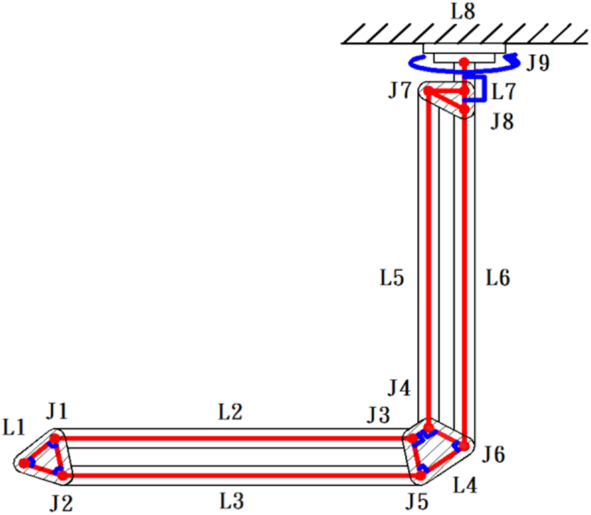
Skeleton of the newly developed palletizing robot arm.
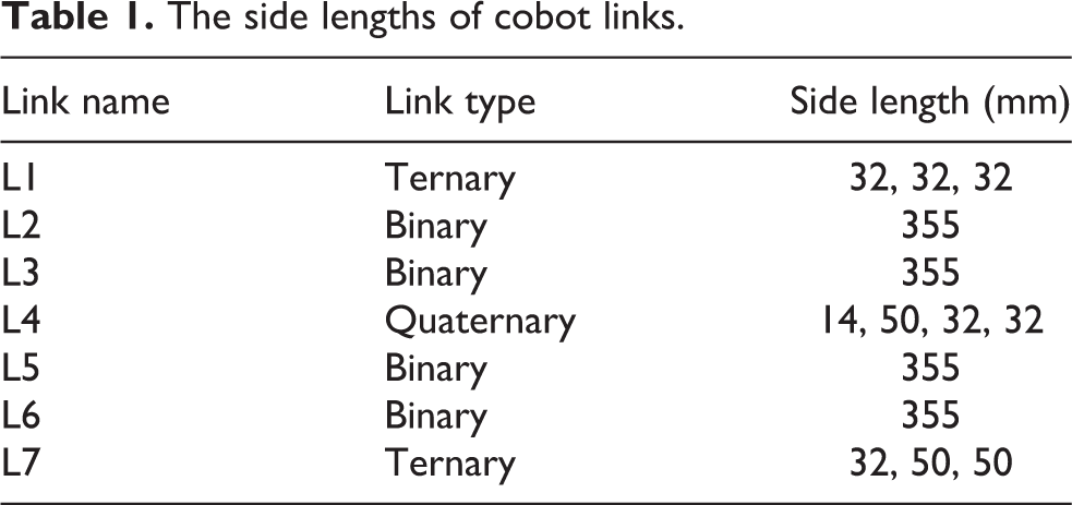
The robot arm has several types of links: four binary (L2, L3, L5, and L6), two ternary (L1 and L7), and one quaternary link (L4), as shown in Figure 2. Side lengths for all links are given in Table 1.
The side lengths of cobot links.
The X–Y–Z coordinate system was used to analyze the motion of the cobot, as shown in Figure 3. Links L2 and L3 were parallel to the ground, and links L5 and L6 were perpendicular to the ground. The cobot arm’s end was defined as the coordinates’ origin.

Representation of the coordinate system for the definition of the working space.
The workspace in which the cobot arm would move was divided into five planes in the Z direction (α 0, α 40, α −40, α 80, and α −80). The origin middle plane was defined as α 0, as shown in Figure 4. The other planes were defined as α 40 and α 80 at 40 and 80 mm, respectively, directly above α 0. The planes α −40 and α −80 are at 40 and 80 mm, respectively, directly below α 0. The initial position of the cobot was set as the origin (0, 0, 0) in the workspace.

Decomposition of the 3D working space in the coordinates system for measuring the hand-guiding force.
The hand-guiding force was measured on each plane while the arm moved horizontally. This is done by fixing Z to a given plane and sweeping the position along the X and Y axes. Starting from the origin point, in the plane α 0, the arm is displaced in the X direction (i.e. X = 0, 40, 80, 120, and 160) for Y = 0. This is repeated for each plane’s different positions in the Y direction, as illustrated in Figure 4. The guiding force is measured for each point in this 3D working space, and the tension gage of this research and its specifications are as shown in Figure 5 and Table 2.

The photo of tension gage
The specifications of tension gage.

Stick–slip measurement scheme
The flowchart in Figure 6 describes the workflow protocol for measuring forces during the hand-guiding operation. First, the robot’s position was initialized at the origin in the defined 3D space. Then the cobot arm is manually guided along X and Y positions for each horizontal plane (i.e. α 0, α 40, α −40, α 80, and α −80). To characterize and analyze the stick–slip phenomenon during the motion of the cobot arm, the hand-guiding force was measured at each position in the 3D space.

Flowchart for stick–slip measurement during hand-guiding motion in the 3D space.
Therefore, 3D plots of the hand-guiding force variations could be constructed by measuring forces at each X, Y, and Z position, as shown in Figure 4.
This allows for the identification of the stick–slip occurrence and the measurement of its resulting force variations. This constitutes a critical motion feature of a cobot, which determines whether the cobot is smoothly and efficiently hand-guided. The reliability of this scheme was successfully verified through repeatable and reproducible measurements.
Results and discussion
At the beginning of this experiment, the robot was guided from the origin to every measurement point on each plane. In the α 0 plane, a first moving force line was measured along the line X = 0 (by changing the Y position), as shown in Figure 7.

2D profile of the measured hand-guiding force in the plane α 0 at X = 0 mm and along the Y-axis direction.
Measured points were fitted with a second-degree polynomial using least-squares regression, representing the smooth motion along the axis in the α 0 plane. The full circular markers, connected by a solid line, represent the experimental force profile along this axis of motion. The dotted line represents the fitted profile in Figure 7. The errors between the continuous and dotted lines represent the variations between the measured and ideal values of the hand-guiding force for the newly developed palletizing robot arm. Stick–slip is observed at Y = 40 mm, where the highest error is identified.The measurement is repeated by moving the robot arm to a new starting point X = 40 mm, on the same plane (i.e. α 0 plane), and the cobot is moved again along the Y-axis, as done in the previous measurement. The new hand-guiding force profile along this axis is measured, as shown in Figure 8. Following the same procedure, the stick–slip is determined at approximately Y = 40 mm.

2D profile of the measured hand-guiding force in the plane α 0 at X = 40 mm and along the Y-axis direction.
Five different measured force profiles were acquired on the plane α 0. Figure 9 shows all profiles plotted on the same 2D chart. Although these profiles point toward a stick–slip occurring around the position Y = 40 mm, this representation remains incomplete to characterize the stick–slip motion in the plane fully. This is because each line profile in Figure 8 represents the hand-guiding motion for a given initial position X and along the running Y-axis. Therefore, it is impossible to identify the stick–slip along the X direction.

Stacked line chart of plane α 0.
We used 3D line charts representing the hand-guiding force variations along all axes. A 3D line chart has an additional dimension. It uses the X-dimension (displacement of the X-axis), Y-dimension (displacement of the Y-axis), and Z-dimension (moving force) to show the measured values. Moreover, the 3D chart is significantly easier to rotate and visualize from multiple perspectives.
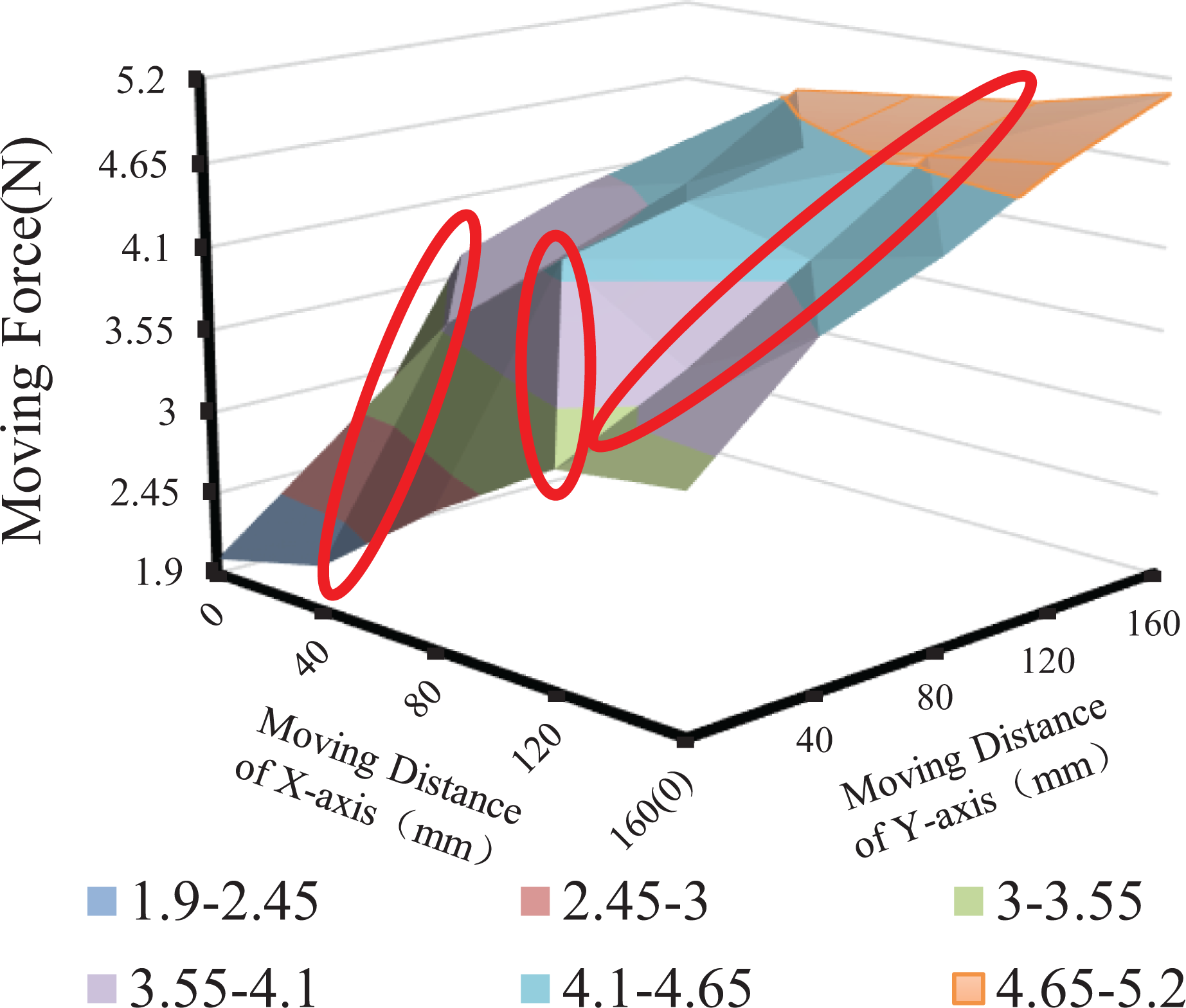
Figure 10 shows the 3D line chart of the force measurements obtained for the cobot arm moving in the plane α 0. This enables the characterization of the in-plane variations of the moving force and the stick–slip phenomenon.

3D chart of measured values of entire initial measurement plane α 0.
Focusing on the marked area, the moving distance along the Y-axis was 40 mm. These variations were analyzed, and a bar chart of the measured values on the initial measurement plane, α 0, was plotted (Figure 11). Subsequently, the hand-guiding performance of the newly developed palletizing robot arm could be determined. Based on the results, the hand-guiding joint operation of the cobot in technical specifications (ISO/TS 15066) can be verified. The stick–slip effect of the fundamental characteristics of the cobot can be investigated.

Moving force variations of the curve (plane α 0, line X = 40 mm).
Next, the measured values of the five planes were used to plot a bar chart representing the hand-guiding performance of the newly developed palletizing robot (Figure 12). For the plane α 0, the maximum variation was identified at approximately Y = 40 mm, followed by Y = 120 and 160 mm. Thus, the stick–slip at Y = 40 mm was the most severe for the cobot arm motion in the plane α 0.
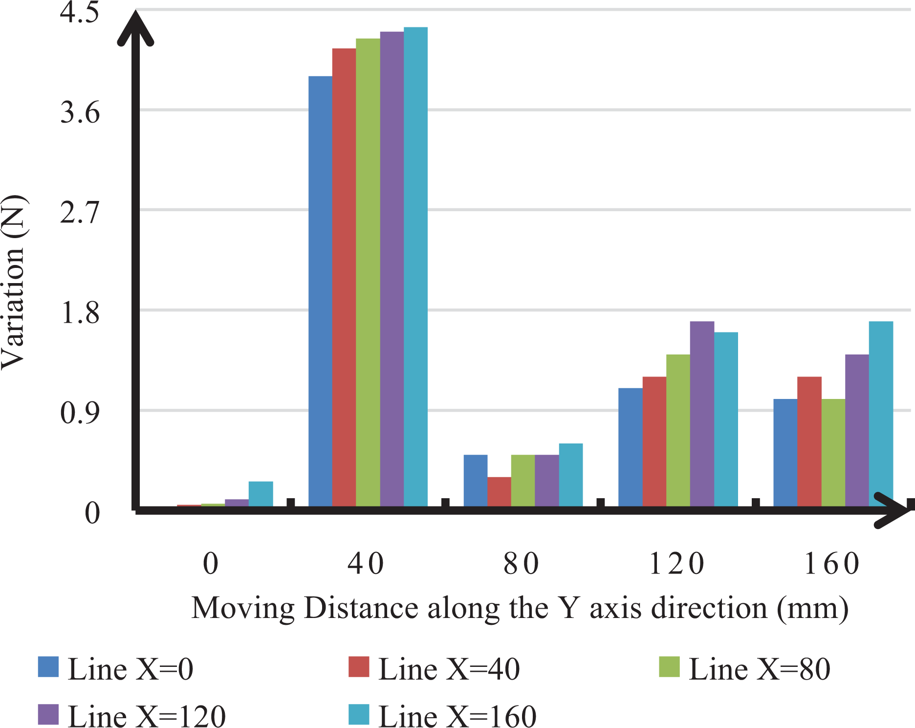
Bar chart group of measured values of entire initial measurement plane α 0.
The same measurement procedure was applied for the arm motion in the plane α 40, which was 40 mm above the plane α 0 (Figure 13). Measurement results show that the 3D force variation profile (chart) in X and Y directions for the motion in the plane α 40 is subsequently different than that in the plane α 0. Rough features on the 3D chart are the signature of a stick–slip occurrence.
3D chart of measured values of entire measurement plane α 40.
For the motion in the plane α 40, more than three rough features are observed at various positions, indicating that the cobot arm’s motion is rough and less smooth compared to the plane α 0.
Similarly, a 3D chart of the measured values for the motion in the plane α −40, which was 40 mm below plane α 0, was plotted (Figure 14). The hand-guiding force values were within 11.3 N; most of the force values ranged between 2.3 N and 9.5 N, and few forces were lower than 2.3 N or higher than 9.5 N. The motion in the Y-axis direction exhibits more significant force variations than in the X-axis.

3D chart of measured values of entire measurement plane α −40.
Figure 14 shows that the stick–slip effect can be easily investigated, and stick–slip motion is likely to occur in the area marked by the red circle.
Measurements in plane α 80, which was 80 mm above plane α 0, clearly highlight even more rough features on the 3D line chart shown in Figure 15. This indicates a less smooth motion of the cobot arm as the plane of motion deviates from the mean initial plane α 0.

3D chart of measured values of entire measurement plane α 80.
Similarly, a 3D chart of the measured values of measurement plane α −80, which was 80 mm below plane α 0, was generated (Figure 16). The 3D chart indicated that the hand-guiding force was within 13.3 N; values mainly ranged between 4.3 N and 11.5 N. Few hand-guiding forces were lower than 4.3 N or higher than 11.5 N.

3D chart of measured values of entire measurement plane α −80.
Moreover, the motion on the Y-axis was more significant force variation than on the X-axis. Figure 16 shows that the stick–slip effect can be assessed, and the marked areas show the possibility of stick–slip motion in the corresponding direction more than in other directions.
Characteristics of guiding force
Based on the aforementioned analysis of the 3D chart plots for the different motion planes in the Z direction, the following characteristics of the hand-guiding motion emerge: The cobot investigated in this study had less significant moving force variations in hand guidance upward than downward because it exhibited a dual-parallelogram linkage mechanism. For a given point in the same plane, the moving force variations in hand guidance farther away from the X-axis are more significant than those from the Y-axis. The moving force variations of the cobot ranged between 3 N and 6 N because roller bearings constrained this mechanism. If the cobot uses sliding bearings to constrain its mechanism, it will produce more excellent resistance to hand guidance. Plane α
0 was assumed as the datum center plane in this study. The upward moving variation force of the cobot was less than 6 N, and the downward moving variation force was less than 14 N. If the moving force variations of the cobot are close to 9 N, the moving force is overloaded. In addition to the datum plane, α
0, the measured values of many points were not very smooth.
Stick–slip of guiding force
Stick–slip significantly influences the hand guidance of the cobot, and changes in the friction properties generally cause its negative impact on the mechanical system.
As it has been shown in Figures 15 and 16, the upward trend of the moving force on planes α 80 and α −80 is not smooth, showing extreme fluctuations. The cobot maintained passive motion throughout, and the moving force variation at each measured point fluctuated, increasing with the distance.
Stick–slip is a significant cause of non-smoothness in the hand guidance of cobots, which prevents the operator from having reasonable expectations of the guiding position and force. The sudden increase and decrease in the moving force during the hand-guiding operation of the newly developed palletizing robot arm may cause accidents for the operator. This is similarly the case with the hand-guiding cobots.
According to the technical specification, ISO/TS 15066, cobots have a mode of operation in which an operator controls them through hand guidance. Several factors influence the accuracy of the end position of cobots. The main factor reported in this study is the stick–slip of robots. If a cobot does not make timely changes to its hand-guiding force, stick–slip becomes inevitable. As stick–slip occurs, the speed and fluctuation of the movement change, affecting the accuracy of the end position.
For traditional industrial robots, preventing the adverse effects of stick–slip is the primary method for compensating the control system. However, the cobot is unsuitable for compensation through control because it should not provide additional power to eliminate the adverse effects of stick–slip in a manual hand-guidance state.
Cobots can only suppress stick–slip when the smoothness of the interface is improved, such as by applying lubricants. The stick–slip reduction can reduce the operator’s burden and improve the cobot’s hand-guidance stability.
This study demonstrates that stick–slip occurs solely on the declining branch of the Stribeck curve. If the frictional force exists at a constant low speed or increases throughout the spectrum speed, damped oscillation or creeping occurs in the system.
Conclusions and future work
Conclusions
In this study, the instability of the hand guidance of a cobot caused by a stick–slip was experimentally confirmed. The main conclusions are as follows: For the experimental setup, the closer the cobot is to the origin point in the space, the lower the hand-guiding force. As the working plane is lowered, the hand-guiding force increases. The stick–slip for hand guidance to plane α −80 is more pronounced than those of other planes. Moving force variations are primarily influenced by stick–slip. Therefore, reducing the stick–slip can improve the hand guidance stability and the positioning accuracy of the cobot motion. The stick–slip effect can be easily determined based on the 3D charts of the measured values for the entire measurement plane.
Future work
Future work should consider increasing the load during the tests to mimic the actual operating environment conditions. The variations in the origin of the robot’s action to increase the experimental group should be investigated to assess the stick–slip effect of hand guidance. Suppose a 3D chart of the measured can be automatically built. In that case, the 3D chart can be easily applied to reduce stick–slip, and then a palletizing robot as a cobot could perform better in controlled precision positioning.
Footnotes
Declaration of conflicting interests
The author(s) declared no potential conflicts of interest with respect to the research, authorship, and/or publication of this article.
Funding
The author(s) received no financial support for the research, authorship, and/or publication of this article.