
Abstract
This article proposes a mutual positioning relay method that enables multiple robots to monitor indoor environments. Here, robots refer to a small number of parent robots with high positioning performance and a large number of child robots with minimal positioning performance. The parent robot can estimate its state accurately by itself. In comparison, the child robots have position errors that accumulate with time as they use only odometry information for positioning. Each robot can recognize other robots in its field of view by using a depth camera. It then performs relative positioning and estimates its position of itself or that of other robots on the map. The uncertainty of the position estimation is compared with each other, and the robot with a certain position becomes a positioning reference for the robot with an uncertain position. In this way, both the parent and child robots relay relative positioning with each other, following which all the robots accurately estimate their positions. In this study, six robots based on Roomba were used. The performance of the proposed method was verified based on experimental data of autonomous navigation tests. Our results showed that the proposed method could realize an accuracy that was four to five times better than that performed independently by a child robot. Our findings also revealed that the proposed method can recover the failure of the state estimation of the parent robot.
Introduction
Currently, humans or surveillance cameras monitor human activities and security in indoor environments such as offices, airports, and shopping malls. However, in recent years, robots are being increasingly used for such applications. Since robots can act as mobile cameras, they can monitor a wider area compared to the surveillance cameras. Additionally, they can reduce the burden on humans with respect to security surveillance. Generally, a single robot, equipped with all sensors necessary for autonomous navigation, monitors the concerned environment. Robots use different positioning methods: a map-based method using Light Detection and Ranging (LiDAR) 1,2 and an image-based method using cameras. 3 –5 However, the robot can cause localization failure even with these methods, especially in environments with few features (e.g. connecting corridors at airports). Additionally, it should also be noted that the robot can only monitor a point at a time and cannot comprehend the continuously changing environment.
The present study proposes a distributed positioning system for indoor monitoring; this system uses few parent robots with high positioning performance and many child robots with minimal positioning performance. The parent robots use a LiDAR and a map to perform accurate positioning, whereas the child robots estimate their positions based on odometry information. Thus, compared with the parent robots, the estimation accuracy of the child robots degrades with time. All robots are equipped with omnidirectional cameras and depth cameras. With the help of its omnidirectional camera, a robot can recognize the other robots. The robot uses its depth camera to estimate its self-position relative to the other robots. The robots then compare the uncertainty of their state estimation with each other. The robot with uncertain estimation performs state estimation based on the relative positioning with the robot whose estimation is certain. Thus, the parent and child robots relay relative positioning with each other, optimizing positioning accuracy as a whole. In this article, a new method to estimate the positions of distributed robots is proposed. This proposed method requires only a small number of parent robots and is, thus, cost-effective compared with other such systems. Moreover, the low-cost robot system can monitor the indoor environment simultaneously and in a distributed way. The proposed method will make it possible for robots with only simple sensors to perform consistent position estimation and be operational while breaking away from the method of monitoring by only robots with expensive sensors. This proposed method will make environmental monitoring by distributed robots a reality. Figure 1 shows the concept of the proposed method.

The concept of the proposed method.
Different studies have proposed multiple homogeneous robot systems for environmental monitoring. The use of high-performance robots guarantees positioning accuracy, but high development costs limit the number of robots used. In comparison, a large number of simple robots can be used, but the positioning accuracy cannot be guaranteed. Some studies have proposed the use of multiple heterogeneous robots for environmental monitoring. A cooperative positioning system that uses a parent robot and child robots can be applied in large-scale map generation. 6,7 However, in this method, either the parent or the child robots need to stop being a reference point for positioning to generate a precise map. Another study has proposed a cooperation method with land and aerial robots. 8 Although several methods using such heterogeneous robots have been proposed, there is little research on parent and child robots, which have lower specifications compared with those of the parent ones in the field of land-based robotics.
Several other studies have proposed positioning methods in which multiple robots estimate their positions by using relative positioning measurements among them. 9 –11 Additionally, studies have also proposed a cooperative localization for unknown initial conditions 12 and a mutual localization algorithm for anonymous position measurements 13 in a relatively small space. A study has also proposed a localization method for multiple robots using ultra-wideband wireless technology. 14
Studies have reported a method for operating a large number of low-cost robots. 15 However, in this case, the accuracy will be difficult to maintain if no positioning reference guarantees absolute positioning accuracy. Some of the proposed low-cost positioning methods for multiple robots are fast and precise vision-based localization, 16 recognizing and positioning with a downward-facing camera, 17 and a measurement system using infrared sensors. 18
Research works have also studied positioning and communication relays to establish high-quality data communication networks. 19,20 However, to the best of the authors’ knowledge, no research work has been proposed to optimize the overall system by dynamically controlling the direction of relaying positioning information.
The contributions of this research are as follows: It proposes and develops a distributed positioning method using multiple heterogeneous robots in an indoor environment that guarantees stable positioning performance. The proposed method uses parent and child robots with different positioning performances to realize a realistic and low-cost multiple robot system. The study shows that the positioning accuracy of the child robots can be improved via relative positioning measurements between the robots. The proposed method can improve the robustness of the state estimation of the parent robot as well as the estimation accuracy of the child robots by comparing the uncertainty of the position estimations of the robots and relaying the mutual positioning measurements optimally. Relaying relative positioning to each other by using a robot with relatively reliable state estimation at a certain time as a positioning reference can delay the increase in position error compared with the condition where a robot of the same performance estimates its state independently.
The rest of this article is organized as follows. The proposed method is explained in the second section. The third section presents the implementation of the proposed method. The fourth section provides the experiments with six robots. Conclusions are presented in the final section.
Method
This section explains the mutual positioning relay method used by a small number of parent robots and a large number of child robots. The parent robots can perform highly accurate positioning independently, whereas the child robots can only obtain simple odometry information. Each robot estimates its state

System architecture. The upper panel indicates the parent robot’s one and the lower panel shows the child robot’s one.
Based on the probabilistic state estimation method, the robot estimates its own state

where I indicates the number of the particles.
In the prediction phase, the robots conduct the state transition from time t to t + 1, whereas in the observation phase, the state distribution is modified based on external observed measurements.
The state from time t to t + 1 in the prediction phase is estimated based on odometry information


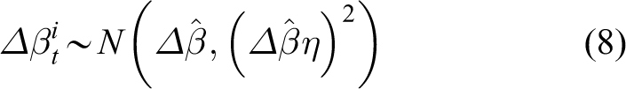


Here, η refers to the noise ratio of the movement,
The standard deviations
The parent robot performs the observation phase using the measurements from the LiDAR

where

where dR
and

Resampling is performed according to the likelihood of the particles to modify the state distribution.
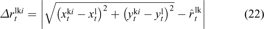
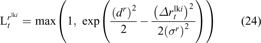
When the robot k recognizes the robot l, the distance

If


Finally, the weight for each particle is determined by multiplying all the likelihoods of measurements as follows:

To modify the state distribution, resampling is performed according to the weights of the particles.
When the robot k is recognized by the robot l and


In the same way, the weight for each particle is determined by multiplying all the likelihoods of measurements as follows:

To modify the state distribution, resampling is performed according to the weights of the particles.
Figures 3 and 4 show a flowchart and all subroutines of the proposed method.
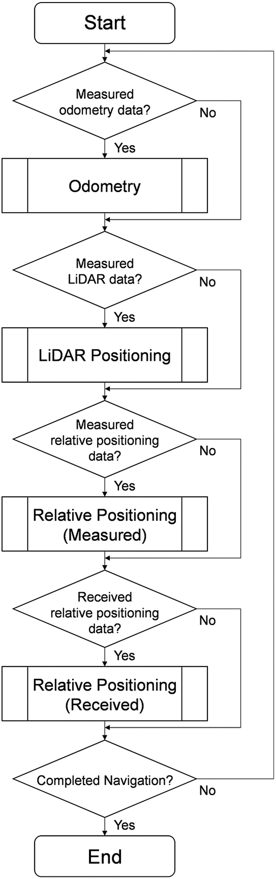
A flowchart of the proposed method. The robot which acts as the child one skips the subroutine of the LiDAR Positioning.

All subroutines of the proposed method: (a) subroutine of the Odometry, (b) subroutine of the LiDAR Positioning, (c) subroutine of the Relative Positioning (Measured), and (d) subroutine of the Relative Positioning (Received).
Implementation
The proposed method was evaluated using robots that were developed based on iRobot Roomba, which is an inexpensive and easily available product robot. Figure 5 shows a photo of the robot developed by using Roomba. For this study, we adopted Intel Next Unit of Computing, which was equipped with an omnidirectional camera (RICOH THETA S) to recognize the robots, a depth camera (Intel RealSense D455) to obtain the relative position of the recognized robot, and an actuator (ROBOTIS Dynamixel MX-28R) to direct the depth camera in the direction of the recognized robot. It was also equipped with a 2D-LiDAR (HOKUYO AUTOMATIC UTM-30LX or UST-20LX). The parent robot uses the LiDAR for positioning, whereas the child robot uses the LiDAR measurements to obtain the true value of its position. Each robot can be identified by detecting the color sheets attached to it. The proposed method was implemented on six robots having the same specifications. Figure 6 shows the robots used.

A robot developed by using Roomba.

Six robots.
Experiments
In an indoor environment, six robots navigated autonomously by estimating their state based on odometry measurements, point cloud data from their LiDAR, and a map. Figure 7 shows the map and the navigation procedure. The six robots started from point 0 at different times and navigated around the floor while maintaining approximately 3–4 m from the other robots. During this time, data from the omnidirectional camera and the depth camera were obtained. Figure 8 shows the scene of the experiment.
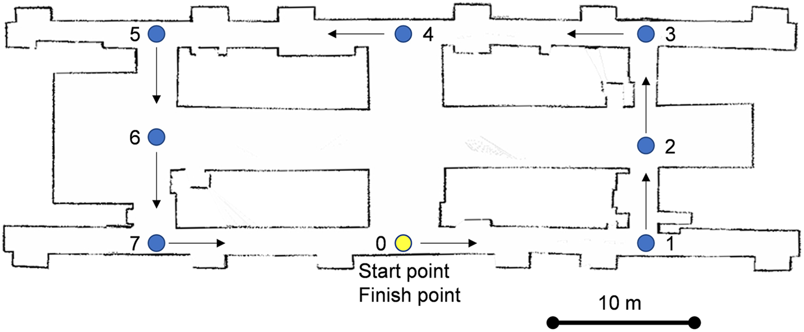
The map and navigation route.

The scene of the experiment.
We estimated the states of the robots based on the following obtained data in post-processing: odometry, point cloud data from the LiDAR and the map, estimated states of other robots and relative positioning measurements.
Table 1 shows the parameters for state estimation. The standard deviations of sensor measurements were determined based on the preliminary experiments.
Parameters for state estimation.

We compared the performance under the following conditions. State estimation for each condition runs 10 times. The robots also used data 2 for the first 20s to reduce the error of the initial position. Condition A: All robots behave as parent robots by using data 1 and 2. Condition B: All robots use only odometry measurements (data 1). Condition C: One parent and five child robots (the first one acts as the parent). Condition D: One parent and five child robots (the third robot acts as the parent). Condition E: Two parent and four child robots (the first and last robots act as the parent ones). Condition F: All robots behave as child robots.
In conditions C to F, the parent robots use data 1, 2, and 3, and the child ones use data 1 and 3.
In the experimental environment, the LiDAR enabled the visibility of almost all areas, so the parent robot was successful in state estimation for all situations. In the actual indoor environment, the LiDAR cannot see far such as in long corridors and plazas. Thus, restrictions were set in the experimental setting that point clouds from the LiDAR cannot be used beyond a certain distance. The valid measurements from the LiDAR were limited to 2 m, and the following conditions are added: Condition A2: All robots use data 1 and 2 (limited to 2 m). Condition E2: Two parent robots and four child robots (the first and last robots act as the parent ones).
In condition E2, the parent robots use data 1, 2 (limited to 2 m), and 3, and the child ones use data 1 and 3.
Figure 9 shows the time-series position errors with error bars. The errors were calculated by comparing the results of condition A and each condition. The error bar shows the standard deviation of position error.

The time-series position errors. The line’s color indicates the robot’s color. The robots navigated in the following order: green, yellow, blue, orange, purple, and magenta.
Figure 10 shows the estimated trajectories of conditions A, B, and E.

Estimated trajectories of conditions A, B, and E. The line’s color indicates the same meaning as in Figure 9.
Figure 11 shows the execution status of the observation phase. It indicates whether the results used in the observation phase were measured by itself or by the other robot. When the robot uses the relative positioning measured by itself, it is plotted by a blue dot, and when it uses the relative positioning measured by another robot, it is plotted by a red dot. The figure is time-synchronized and arranged in running order from the top. No dots indicate two situations: either the depth camera cannot measure the relative position of the other robot or the other robot has uncertain position estimation compared with its own and relative position measurements are being used.

Execution status of the observation phase. It indicates whether the robot used the results measured by itself or by the other robot.
In condition B, the errors of the fourth and fifth robots are more than 10 m, as shown in Figure 9. Similarly, Figure 10 shows that the trajectories of the fourth and fifth robots are highly distorted. When the robots changed their directions, their orientation errors may increase. This resulted in position errors.
In conditions C and E, the errors are stable at approximately 1 m. The errors tend to increase when the robots cannot observe the other ones, but the errors are recovered when the robots can observe each other again. In Figure 11, it can be found that all child robots use mutual positioning measurements from both themselves and other robots uniformly.
In condition D, the error of child 1 increased in Figure 9 when the periods were 75–100s and 225–250s. The causes can be analyzed from Figure 11. In the first period, child 2 could not recognize child 1 with its depth camera, and thus, child 2 could not obtain relative positioning measurements. In the second period, child 2 tended to use relative positioning information with child 1, and child 1 could not conduct the observation phase with this information.
Since condition F has no parent robot, the child robot with relatively low position uncertainty becomes the positioning reference and relays relative positioning. Although the error in condition F gradually increases, the average errors are approximately 4–5 m. The errors are smaller than those in condition B, where each child robot is used independently. Relaying relative positioning to each other using a robot that performs relatively reliable state estimation at a certain time as a positioning reference can delay the increase in position error compared with the condition where a robot of the same performance estimates its state independently.
Figure 12 also shows the time-series position errors with error bars in conditions A2 and E2. In condition A2, the errors tend to increase approximately 50s and then after 100s from starting each navigation because position correction based on the LiDAR cannot be sufficiently performed in point 1 or the long corridor from point 3 to point 5 on the map.

The time-series position errors. The line’s color indicates the same meaning as in Figure 9.
On the other hand, in condition E2, all the robots were able to perform almost stable state estimation. The error in parent 1 increased at approximately 50s when it had just turned at point 1. It was temporarily unable to correct its error because child 2 could not observe parent 1 with its depth camera. The errors in parents 1 and 2 increased from 175s to 220s because they could not perform the observation phase based on measurements from the LiDAR in the long straight corridor correctly. The parent can conduct the observation phase when its uncertainty is greater than those of the surrounding child robots, which caused temporary ups and downs in the error.
The execution status of the observation phase for condition E2 is plotted in Figure 11 as well. From Figures 11 and 12, it can be found that the parent robots also perform the observation phase based on the relative positioning information from the child robots when the errors of the parent robots increase and reduce the average errors from around 3 m to around 1.5 m. The repeatability of the results is also guaranteed since the standard deviations of the errors become more than half smaller compared to those without the proposed method.
Based on the above results, it can be considered that the proposed method contributes to improve the accuracy and the robustness of the state estimation thanks to the mutual positioning relay.
Conclusion
This article proposed a mutual positioning relay method of multiple robots for monitoring indoor environments. In the proposed method, the robots consist of a small number of parent robots and a large number of child robots. The parent robots have high positioning performance, whereas the child robots have minimal positioning performance. The parent and child robots use their cameras to recognize each other and perform relative positioning when another robot enters their field of view. The uncertainties of the estimations are compared with each other, and the robot having an uncertain state estimation revises its state based on the positioning measurements relative to the robot having a certain state estimation. The performance of the proposed method was verified through experimental data obtained from an autonomous navigation test with six robots. The proposed method was found to be highly accurate by more than four to five times compared with the method which uses only child robots. It was also shown that the proposed method can recover the state estimation failure of the parent robot. Future works include the development of the state estimation method even when the child robots navigate far from the parent robot.
Footnotes
Acknowledgements
This study was conducted under “Research Cluster for Autonomous Robotic Systems” at Meiji University.
Declaration of conflicting interests
The author(s) declared no potential conflicts of interest with respect to the research, authorship, and/or publication of this article.
Funding
The author(s) received no financial support for the research, authorship, and/or publication of this article.