
Abstract
For patients with upper limb dysfunction after stroke, robot-assisted rehabilitation training plays an important role in functional recovery. The existing upper limb rehabilitation robots have some problems, such as complex mechanisms, insufficient compliance, and can only realize the rehabilitation training of shoulder and elbow joints in the horizontal plane. This research proposes a novel end-effector upper limb rehabilitation robot with three degrees of freedom. Two horizontal rotation freedoms are driven by motors and one vertical translation freedom is driven by a pneumatic cylinder. So it can realize the spatial rehabilitation training of shoulder and elbow joints. The rotation and translation transformation of the robot can be represented by a dual quaternion, which is concise in form and clear in the physical meaning. Therefore, this article adopts dual quaternions to complete the robot’s kinematics modeling, inverse kinematics calculation, and terminal spiral motion trajectory planning. To improve the low-speed moving performance of the spiral motion, a sliding mode control strategy plus feedforward compensation is employed to control the displacement of the cylinder. Experiments show that the robot can realize proximal joints training and has good position tracking accuracy (tracking error is within 2 mm) with smoothness under the proposed control strategy, which can guarantee the accuracy and comfort of passive rehabilitation training, contributing to restoring the function of the impairment upper limbs.
Keywords
Introduction*
At present, the number of stroke patients is still increasing. The quality of their life is diminished greatly due to arm dysfunction, 1 and the situation creates a huge burden on the country and society. 2 Evidence-based medicine indicates that high repetitive exercise training of upper limbs has an impressive effect on improving the upper limb motor function. 3 Since the training helps patients with stroke reestablish the motion control ability of the brain based on brain plasticity, exercise rehabilitation therapy is currently the most popular rehabilitation method. 4 However, most of the current upper limb rehabilitation training is one-on-one manual training supervised by therapists, which is inefficient, labor-intensive, and the effectiveness of rehabilitation regime is easily affected by the state of the therapists. With the development of robot technology, it is wise to use robots to assist therapists to complete repetitive training actions, so the research of rehabilitation training robots has attracted more and more attention at home and abroad.
Upper limb rehabilitation robots are generally divided into two categories: exoskeleton type and end-effector type. 5 The exoskeleton robot should be designed according to the anatomical structure of the upper limbs. Only when the joint axis of the robot is coaxial with the joint axis of the human limb can it assist in rehabilitation training. The typical exoskeleton upper limb rehabilitation robots include L-EXOS, 6 ARMin, 7 Rupert, 8 and so on. The exoskeleton robot can accurately determine the posture of the upper limbs of the human body, but due to the multiple “bundling” between the exoskeleton robot and the upper extremity, the patient is at risk of secondary injury. 9 Relatively, the end-effector robot only relies on the coupling of the robot’s end handle and the patient’s hand to complete rehabilitation training, which improves the safety of the rehabilitation training. 10 The typical robots of end-effector form are MIT-MANUS, 11 MIME, 12 ARM-GUIDE, 13 NeReBOT, 14 SPINDLE, 15 and so on. Individually, MIT-MANUS is a two degrees of freedom robotic manipulator. Based on the parallelogram structure that assists shoulder and elbow movement by moving the hand and forearm of the patient in the horizontal plane, MIME incorporates a PUMA 560 robot that applies forces to the paretic limb during unilateral and bilateral movements in three dimensions, ARM-GUIDE is a device which is attached to the patient’s forearm and guides the arm along a linear path having a variable angle with respect to the horizontal position, and NeReBOT is a cable-driven robot consists of a set of three wires independently driven by three electric motors. SPINDLE is a compact 3-RRR spherical parallel instrument for daily living emulation. It consists of three legs with three revolute joints and can create full-fledged three axial rotations in a large workspace.
Although the end-effector based robots are diverse, there still exists some drawbacks that hinder the clinical applications of end-effector rehabilitation robots, for example, the training restricted in the horizontal plane, high cost of using an industrial robot, complex structure, imprecise position control, and so on. Therefore, we design a novel three degrees of freedom (3DoFs) upper limb rehabilitation robot with a compact structure, aiming for training in three-dimensional (3D) space not only carried out in a hospital by the therapist but also at home by the patient’s family.
The rehabilitation robot proposed here consists of two horizontal rotational joints and one vertical prismatic joint. In terms of safety, the prismatic joint uses a pneumatic cylinder as the actuator to increase passive compliance. The robot realizes 3D rehabilitation training using the least three degrees of freedom and makes the spatial training trajectory easier to be decomposed into the movement of each joint. It will also be relatively simple for motion control because the third joint is decoupled with the first two joints.
A kinematics model is needed before motion control. The classical approaches to the description of joint kinematics are the Denavit–Hartenberg (DH) convention. 16 A 4 × 4 homogeneous transformation matrix is used to represent the transformation of points. The coordinate systems are described with respect to the previous one. The product of exponentials (POE) model with twist coordinate parameters, on the other hand, parameterizes the absolute initial location of each joint axis with six parameters, and only one reference frame and one tool frame are involved. 17 Both of the two methods convert to homogeneous transform matrix (HTM) in the end. The advantage of using unit dual quaternions is that they are more compact than HTM, as the former has eight elements whereas the latter has sixteen. In addition, dual quaternions have strong algebraic properties and can be used to represent rigid motions (rotation and translation) in a very straightforward way. 18 Taking the advantages of dual quaternion and the structural characteristics of the robot into consideration, the dual quaternion is used to establish the kinematics model of the robot and plan the end effector’s spiral trajectory. The process is the backstepped representation of endpoint coordinates. “Backstepped” means the representation is firstly in the last coordinate and finally in the base coordinate. During the spiral motion, crawling is a major problem when the cylinder is moving at a low speed. Many researchers have studied the position control strategy of the cylinder, which mainly includes the friction identification and then compensation method, 19 fuzzy proportional–integral–derivative (PID) method, 20 sliding mode control (SMC) method, 21 predictive fuzzy control with the help of neural networks, 22 and so on. In this article, the SMC plus feedforward compensation method is adopted to control the position of the cylinder moving at low speed. The spiral motion of the robot can drive the impaired arm doing flexion/extension (flex/ext) of elbow joint and abduction/adduction (abd/add) of shoulder joint in the transverse plane (TP) as well as flex/ext of shoulder joint in the sagittal plane (SP) simultaneously.
The main contributions of this article include the following: Firstly, a novel end-effector upper limb rehabilitation robot is proposed, which is composed of two horizontal rotating joints and one vertical prismatic joint, meeting the needs of upper limb rehabilitation training in 3D space. Secondly, the prismatic joint is actuated by a pneumatic cylinder, which increases the passive compliance of the robot. Due to the air compressibility, the process of patient–robot interaction will be safer than rigid contact. Thirdly, the dual quaternion theory is used to complete the kinematics modeling of the robot and the end spiral trajectory planning in detail, which is prepared for passive rehabilitation training control. On the other hand, the active training can be developed in the future owing to the system contains two rotary encoders, one 3D force sensor, and one displacement sensor, and so on.
The rest of this article is organized as follows: Firstly, we introduce the structure of the robot and the components of the system in detail. Secondly, the process of kinematics modeling, the spiral motion trajectory planning, and the motion control strategy are presented. Finally, the correctness of the kinematics model and the effectiveness of the control strategy are verified through the experiment.
Design of the robot system
According to anatomical medicine, the human shoulder joint includes 3DoFs named flex/ext, add/abd, and medial rotation/lateral rotation (mr/lr). Whereas, the elbow joint includes 1DoF (flex/ext). To achieve spatial rehabilitation training for the shoulder and elbow, this article proposes a 3DoFs end-effector upper limb rehabilitation robot (Figure 1).

Robot structure diagram (Z 1, Z 2, Z 3 represent the three joint axis and the parameters θ 1, θ 2, θ 3 denote the joint position, respectively).
The rotation joints driven by the servo motors can realize the add/abd movements of the shoulder in the horizontal plane and the flex/ext motion of the elbow joint. The prismatic joint driven by a cylinder can realize the flex/ext of the shoulder in the SP and mr/lr of the shoulder in the frontal plane (FP).
According to the statistics of Chinese adults, 23 95% of upper arms within 313 mm, forearms within 233 mm, 24 the shoulder add/abd angle of 60°/−100°, shoulder mr/lr angle of 90°/−45°, and the elbow flex/ext angle of 140°/0°. The length of the arms and the range of motion (ROM) of the joints are determined and presented in Table 1. Because of the limitation of the height of the robot, the stroke of the cylinder is designed to be 150 mm, which cannot satisfy the ROM of shoulder flex/ext of 60°/−90°. The workspace analysis (Figure 2) pictures the ROM mentioned above and we can see that the robot can realize all the exercises in the horizontal plane but partial in the SP and coronal plane. Figure 3 shows the simulation of the available rehabilitation training. In detail, (a) is the shoulder flex/ext in the SP, (b) is the shoulder add/abd in the FP, (c) depicts the shoulder add/abd in the TP, (d) depicts the elbow flex/ext in the TP, and (e) shows the shoulder mr/lr in the FP.
The length of arms and ROM of joints.

ROM: range of motion; H: human; R: robot.
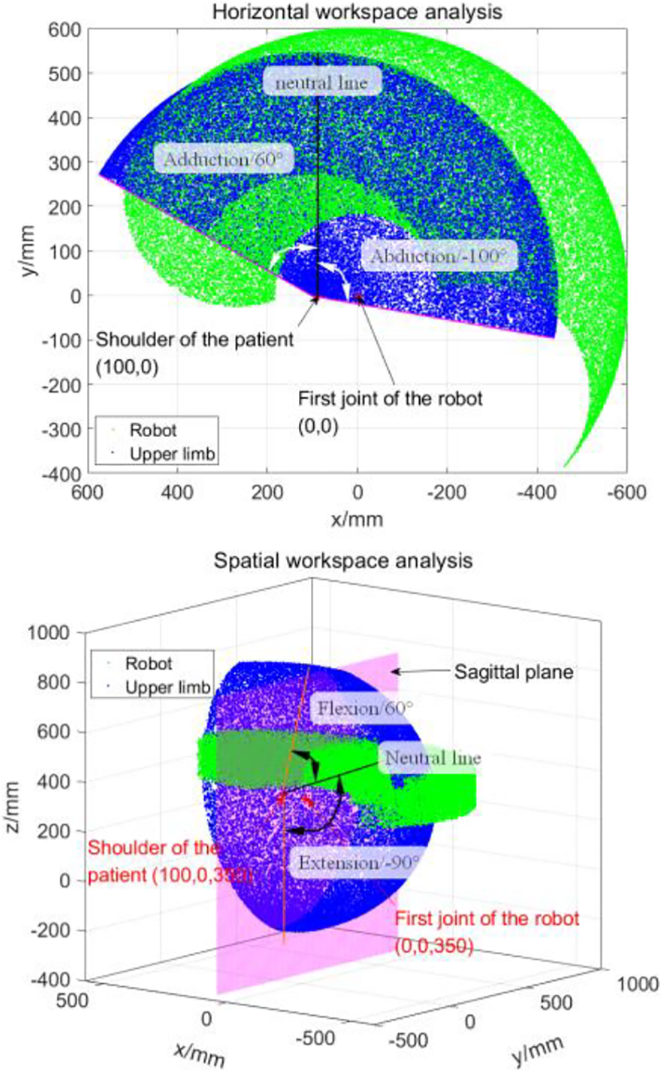
Analysis of the workspace (the green part represents the robot and the blue part is the human upper limb).

Rehabilitation of shoulder and elbow in simulation (the green arrow is the axis and red represents the direction).
To reduce the moment of inertia, the robot’s arms are made of aluminum alloy. The arms are processed into hollow box structure to facilitate wire arrangement and assembly of other components. The drive components of the robot’s rotary joints include AC servo motors, synchronous belts plus harmonic reducers, and the rotation angle of the joints is recorded by the absolute encoder of the servo motor. The motion of the prismatic joint is driven by a pneumatic cylinder, which increases the passive compliance of the robot. The gas pressure of the piston chamber of the cylinder is controlled by a proportional pressure valve, the gas pressure of the rod chamber is set by a manual pressure valve, and the actual pressures of the two chambers are detected by two pressure sensors. The vertical displacement of the cylinder is realized by adjusting the gas pressure of the rodless cavity, and the displacement is detected by a displacement sensor installed at the end of the rod. A 3D force sensor is installed at the bottom of the cylinder to detect the human–robot interaction force during the rehabilitation training.
The hardware of the robot’s control system mainly includes host computer, slave computer (Links-Box, Beijing LinksTech Co. Ltd., Beijing, China), motion control card and high-performance servo driver. The control software of the system mainly comprises MATLAB and RT-sim. MATLAB is mainly used to construct the mathematical and control algorithm model of the system. RT-sim is responsible for the actual operation of the hardware-in-the-loop simulation program, the real-time monitoring, and storage of data. The apparatus of the rehabilitation robot system is shown in Figure 4. The system components are shown in Figure 5.

The apparatus of the rehabilitation robot system.

Rehabilitation robot system composition diagram.
Kinematics model of the robot
Dual quaternion was proposed by William Kingdom Clifford in 1873. It has a similar expression form to quaternion. The difference is that the quaternion can only express the rotation transformation of a rigid body. It can be seen from the structural design part of the upper limb rehabilitation robot that the motion of the robot includes rotation and translation, so the quaternion cannot fully express the joint motion of the robot. The dual quaternion is an 8-tuple that can not only represent the rotation of a rigid body but also represent the translational transformation of a rigid body, unifying the two movements of a rigid body. It can express rigid body transformation concisely with clearer physical meaning, showing its superiority. 25 Therefore, this article adopts the theory of dual quaternion to model and analyze the kinematics of the 3DoFs upper limb rehabilitation robot in 3D space.
Some mathematical foundations related to dual quaternion
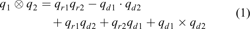
a. The multiplication rule of quaternions.
b. The conjugation of a quaternion. Take q 1 as an example, its conjugation is represented by

c. The multiplication rule of dual quaternions.

d. Three kinds of dual quaternion conjugation.
Taking the dual quaternion a. b. c.
It can be seen that the third type is a combination of the first two. The different conjugate form is suitable for different rigid body transformation objects.
The second type is suitable for rigid body transformation of a straight line, and the third type is used for point rigid body transformation.
The kinematics model of the robot
Note: To simplify the expressions later in this article, define the following abbreviated expression

Suppose the coordinate of a point is
Establish the coordinate system {O1} and {O2} at the first two rotary joints as shown in Figure 6. The angular displacements of the two rotation joints are

Schematic diagram of robot joint coordinates.
Step 1: Pick a point at the initial position.
Take an arbitrary point P on the axis of the prismatic joint, and the coordinate of point P relative to the coordinate {O2} is P (a2,0, H+d). Its dual quaternion representation is as follows

Step 2: Calculate the coordinate of P relative to {O2} after rotation of
The robot’s second rotary joint represents a rotary transformation, which can be expressed as the following dual quaternion

So its conjugate is succinctly expressed as

Through the calculation of
Note: Because we can distinguish whether it is a quaternion or a dual quaternion through the expression (e.g.
Step 3: Express {O2} with respect to {O1}.
From Figure 6, we can get that {O1} can be identical to {O2} after translation of a1 and rotation of θ
1 in succession. The transformation of a1 and

where

And its conjugation is described by the following expression

Step 4: Express point P relative to {O1}.
Supposing that P becomes

Replace the parameters (a1, a2) in (7) with specific values and calculate the representation of point P in the coordinate system {O1}.

The above formula establishes the mapping from the joint space to the end Cartesian space, which is much more concise than the homogeneous transformation matrix.
Inverse kinematics
Suppose that

Because

Calculate both sides of the equation, we can get the following two equations


Obviously, the elements at corresponding positions are equal. We can get the following equations

There is one unique solution to the equation system. Define

Then substitute formula (11) into (10)

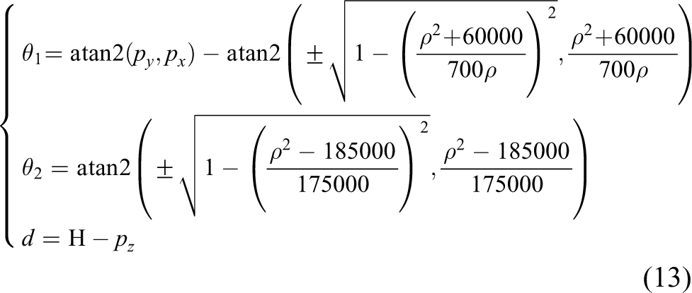
After some trigonometric calculation, we can get the inverse solution as follows
Control strategy of the air cylinder
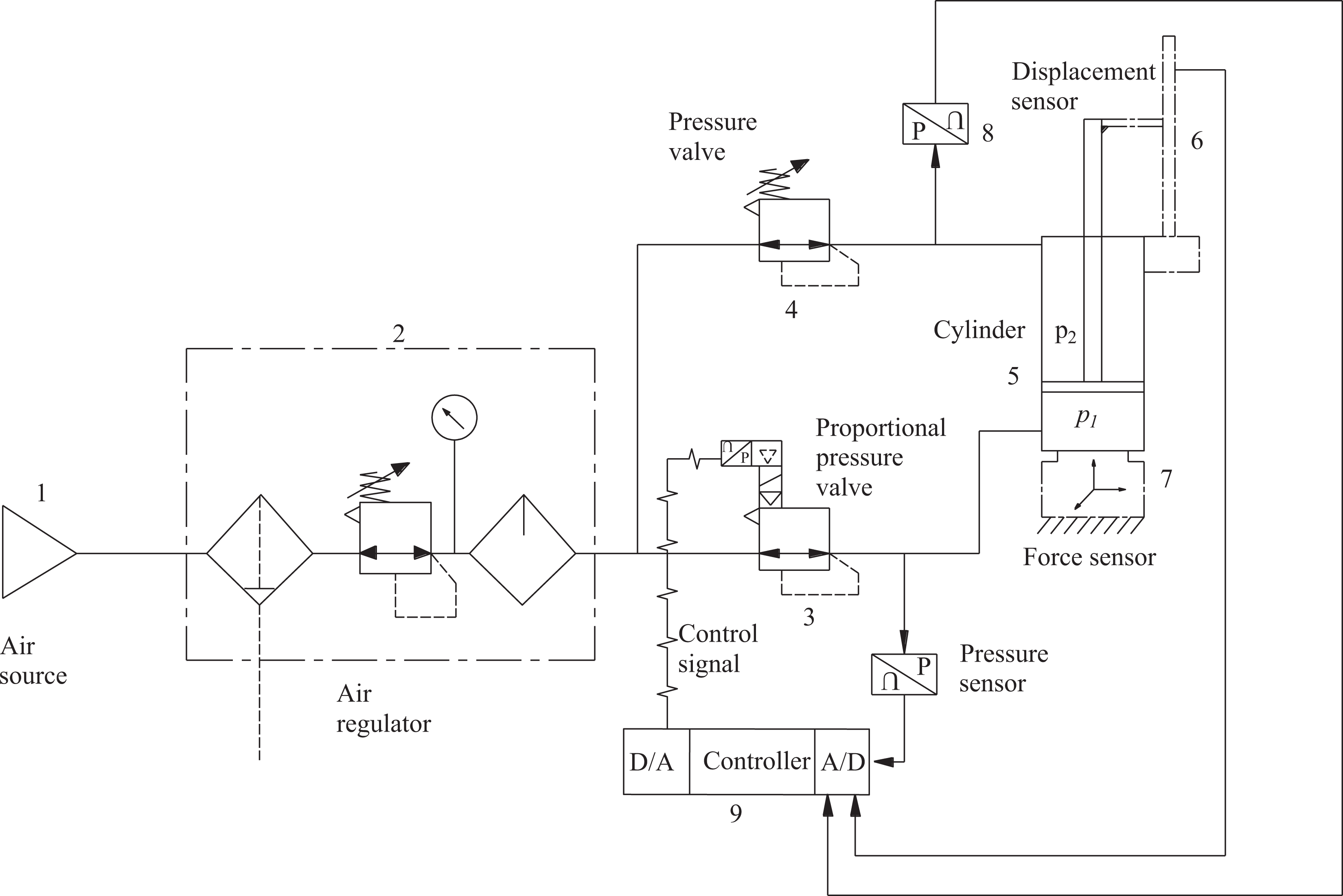
The third joint driven by the cylinder is in an independent servo control circuit. The pneumatic loop is shown in Figure 7. The proportional pressure valve 3 is used to control the pressure p 1 of the rodless cavity of the cylinder 5. To make the cylinder rod extend and return smoothly, the manual pressure valve 4 is connected to the rod cavity of the cylinder, and a fixed gas pressure p2 is set to maintain the backpressure. The cylinder rod is moved by adjusting the air pressure p 1 in the rodless cavity. At the same time, a displacement sensor 6 is connected to the end of the cylinder rod to feedback the displacement information to controller 9 to form a closed loop.
Pneumatic servo loop.
In the process of rehabilitation training, for the sake of safety, the cylinder requires a relatively low moving speed, because slow and repeated motions can help reduce spasticity 26 and also minimize the undesirable reflex contributions. 27 But crawling will inevitably occur at low speeds. Therefore, it is necessary to model the pneumatic servo system and study the control method. The mathematical model of the general pneumatic servo system includes (1) the dynamic equation of the actuator; (2) the pressure differential equation in the cylinder chamber; (3) the mass flow equation at the outlet of the proportional pressure valve. It is difficult to establish a precise mathematical model, so it is more usual to achieve system tracking control based on a simplified model with a robust control algorithm. The SMC method is widely used because of its fast response and strong anti-interference ability. 28 In this article, feedforward compensation plus sliding mode strategy is used for control.
Design SMC
Firstly, the friction force of the pneumatic servo system is ignored and the pneumatic servo system is simplified to a linear system. Take the displacement of the cylinder as the state x 1 and the moving speed as the state x 2. Then the state equations of the system are defined as follows
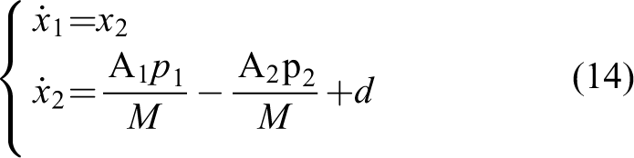
where
Let error (e) equals r minus x, where r denotes the desired input and x is the real output. During the experiment, set u2 to be a constant. The switching function of the sliding surface is expressed as the following equation

The reaching law is defined in the following form

Using the formulae (15) and (16), the input of the system can be calculated as

Let the Lyapunov function of the system be

then, the derivative of V is written as

Substitute the control input represented by equation (17) into equation (19), we can get the final expression of

If

In the experiment, the values of the parameters in the sliding mode controller are k = 20, c = 30, ε = 0.2, and Δ = 1.
Feedforward compensation
A simple test of the static friction force of the cylinder is carried out. With the aid of the 3D force sensor (number 7 in Figure 7) installed at the bottom of the cylinder, while pulling the cylinder rod, the force in the vertical direction is measured when the moving direction of the cylinder changes, which is considered as the estimated value of the static friction force. The test result is shown in Figure 8. It can be seen that the force is about 15 N when the moving direction changes. When the cylinder moves at a certain speed, the friction force appears as a velocity-dependent viscous friction force, which is set to be 8 N. It iss smaller than the static friction force.

Test of static friction.
The friction compensation can be expressed as the following formula

Feedforward compensation also includes compensation for external load changes. For example, the weight of the upper limbs of different patients is different, and the load change can be directly detected by the 3D force sensor and converted into the pressure change in the cylinder cavity that can be compensated. Therefore, the overall feedforward compensation is deduced as below

where F load is the external load, while kv and A1 are the same as equation (14).
The control of the revolute joints relies on the three-loop (position–velocity–current) PID control strategy designed in the servo drive. The overall control block diagram is shown in Figure 9 (q d denotes the desired joint angle and q r denotes the real angle).
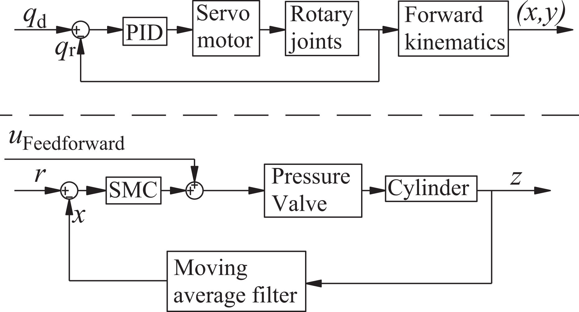
Control block diagram of the system.
Trajectory planning
The upper limb rehabilitation robot proposed in this article can realize 3D rehabilitation training. According to the structural characters of the robot, the screw motion is one typical type of the 3D motions combined by horizontal rotation and vertical translation. This motion can perform more comprehensive training on the shoulder and elbow joints simultaneously. The spiral motion trajectory is depicted in Figure 10 with the green dashed line representing the projected circle trajectory in the horizontal plane.

Spiral trajectory.
Step 1: Compute the quaternion form of the endpoint at its initial position.
Establish a coordinate system {O} at the first revolute joint. Define the center of the horizontal projection circle is (250,300) relative to {O} and the radius is 150 mm. Therefore, the start-point P of the trajectory in {O} is expressed as P(400,300,0), and rewrite the form of P into a dual quaternion is
Step 2:-Calculate the real-time coordinates of the end trajectory point through the relationship between the screw motion parameters and the dual quaternion.
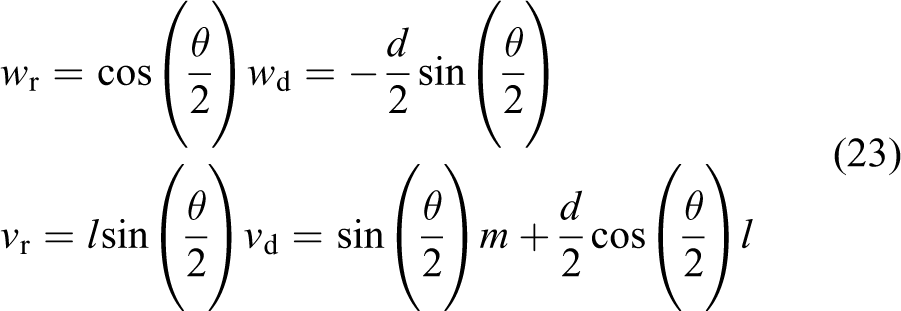
The screw coordinate of a line consists of the direction vector and the moment of the line relative to the coordinate origin. It can be seen from Figure 10 that the direction of the screw axis is
The planned spiral motion can be converted into the dual quaternion representation
That is, the spiral motion is expressed by the following dual quaternion.

Its conjugate is written as below equation
After calculation of
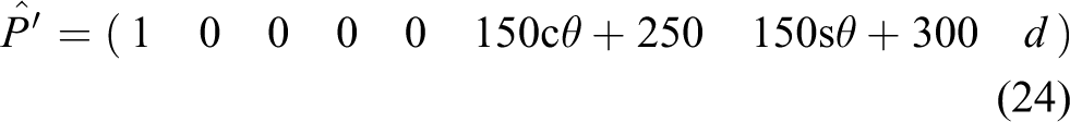
Planning θ changes from 0 to 4π based on the S-curve motion profile model which consists of seven distinct phases of motion, and then the kinematic curves of x, y, and revolute joints are deduced (Figure 11). Meanwhile, to simplify the process of trajectory planning, d changes from 0 mm to 140 mm according to the following expression

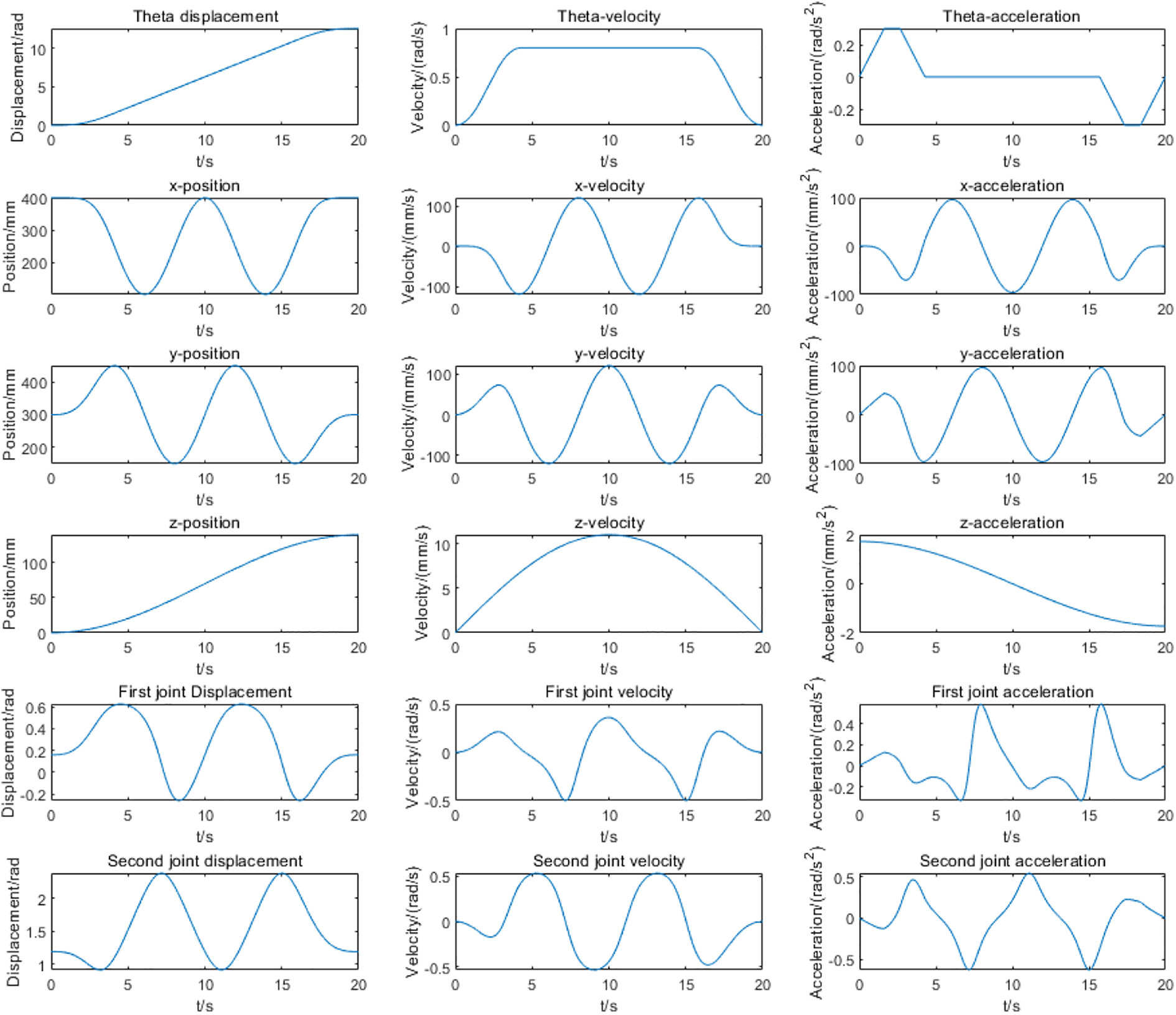
Kinematics profiles of the proposed S-curve model.
Experiment
Firstly, perform the low-speed moving control test of the cylinder. During the test, the cylinder input signal is a sine curve at the frequency of 0.025 Hz described by equation (25). Then implement the PID control method and the control strategy mentioned above separately and compare the effects.
The PID control strategy (k p = 0.2, k i = 0.02, k d = 0.005) performance (Figure 12) and SMC effect (Figure 13) formed a contrast and the correlation coefficient between actual trajectory and desired input are RPID = 0.9990 (under PID control) and RSMC = 0.9993 (under SMC), respectively. On the other hand, the standard deviations of tracking error (Figure 14) are SPID=2.2534 mm and SSMC=1.8372 mm, respectively. In addition, the control input voltage u 1 of the system changes during PID control and SMC is pictured in Figure 15. It can be seen that when the SMC is adopted, the amplitude of high-frequency oscillation is much smaller. From the contrast analysis, we can get that the SMC strategy outperforms PID control.

Performance of PID control (f = 0.025 Hz). PID: proportional–integral–derivative.

Performance of SMC (f = 0.025 Hz). SMC: sliding mode control.

Trajectory tracking error under PID and SMC. PID: proportional–integral–derivative; SMC: sliding mode control.

System control input voltage during PID and SMC. PID: proportional–integral–derivative; SMC: sliding mode control.
Furthermore, the anti-interference experiment was carried out on SMC strategy. The result is depicted in Figure 16. It can be seen that the SMC strategy has a good anti-interference ability. Specifically, as case I in the figure represents the small load interference of Z-direction emulating the different load of the patient arms, the actual position does not fluctuate; case II represents large impact interference. It can be seen that the actual position deviated accordingly, but with the disappearance of interference, the real position can quickly return to the desired trajectory; case III represents large interference lasting for a while. It can be seen that the actual position can return to the desired trajectory within 1.5s after the interference appears. Cases II and III mimic the state of muscle spasm.
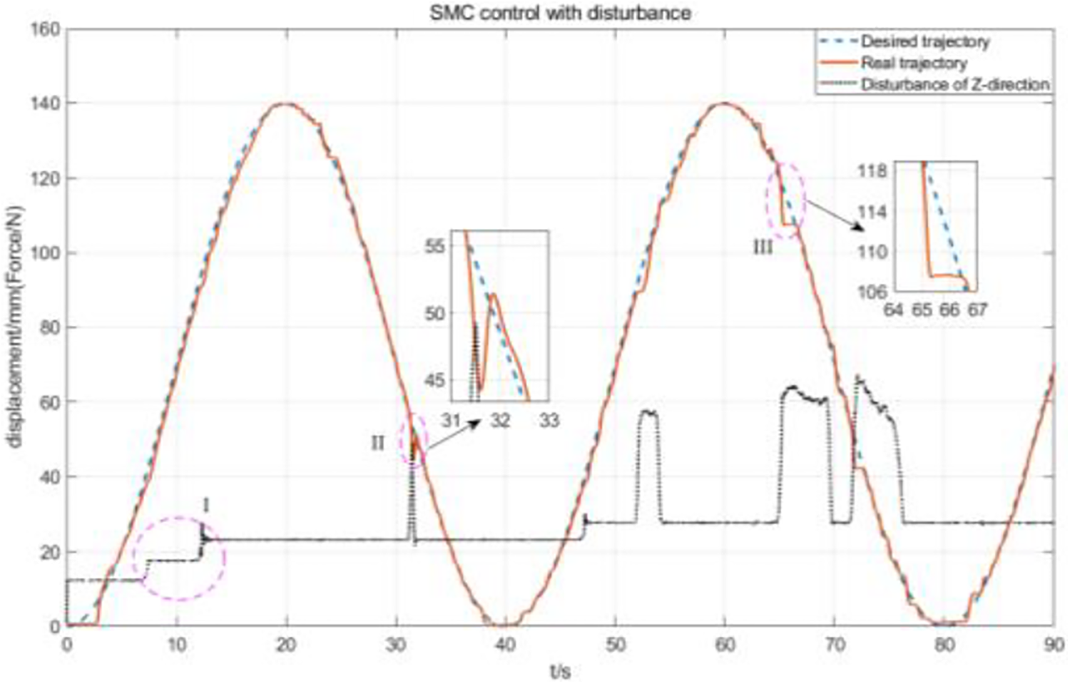
SMC with disturbance. SMC: sliding mode control.
Finally, the spiral trajectory tracking experiment is conducted by four healthy people. Their information is presented in Table 2. Through the experiment, the different volunteer is driven by the robot to complete the trajectory and the system could stay stable. Figure 17 shows four snapshots of the experiment conducted by S1 and Figure 18 shows the tracking results. The blue dashed line represents the expected spiral trajectory, and the red solid line represents the real position. It can be seen that the real trajectory can track the expected input well, verifying the correctness of the kinematics model and the effectiveness of SMC for the pneumatic cylinder. The spiral motion can emulate some activities of daily life (ADLs), such as stirring for cooking, taking the cup for drinking, moving objects on the table, and so on. Single joint rehabilitation training involved with S3 (Figures 19 and 20) is also conducted to simulate the table cleaning action of daily life.
Information of the people involved in the experiment.

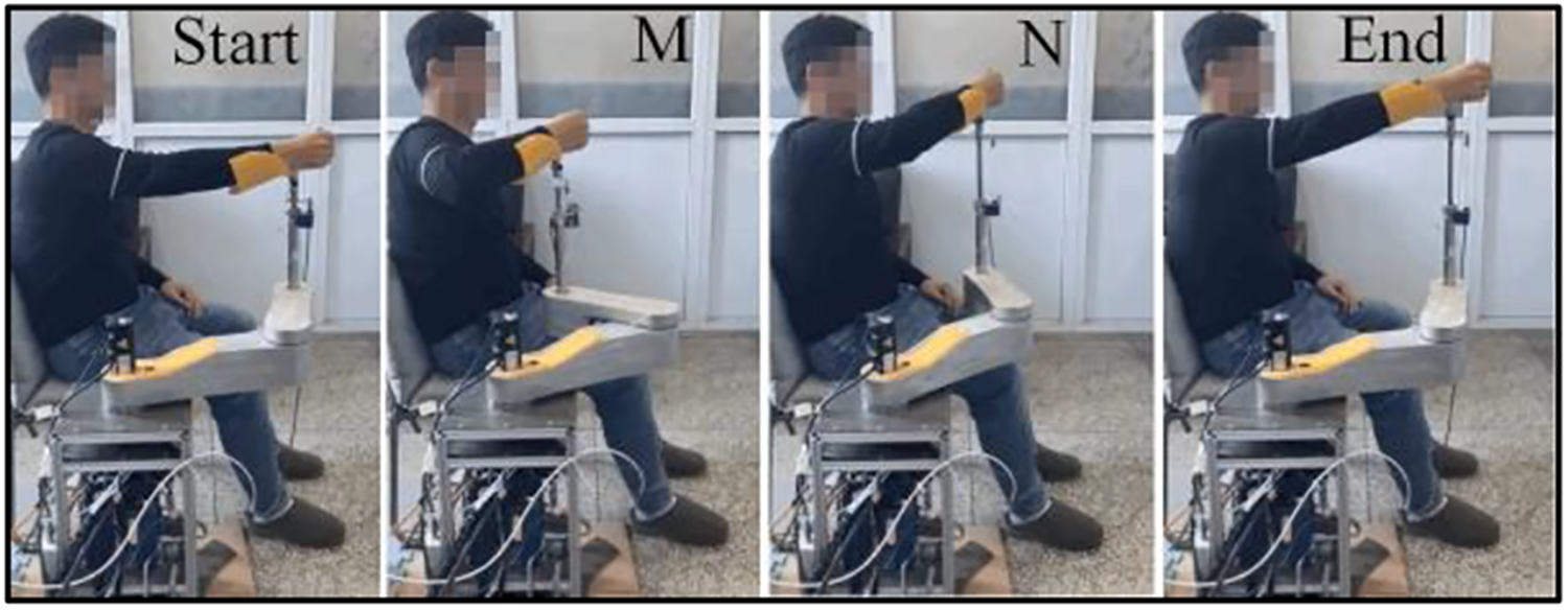

Spiral trajectory tracking experiment result.
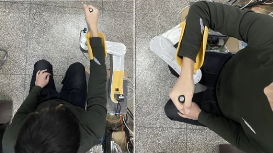
The rehabilitation training of elbow ext/flex.

The rehabilitation training of shoulder add/abd.
Discussion
The upper limb rehabilitation robot proposed here can realize spatial training of shoulder and elbow joints. It has a simpler structure than ARM-GUIDE and NeReBOT. It also has a smaller size than ERA, 30 which is constructed with three orthogonal prismatic joints. On the other hand, the prismatic joint eases the translation as the last joint than the first joint. From Figure 2, Figure 3, and the experiments above, we can see that the robot’s structure allows to drive the upper limb to complete the repetitive passive training in the horizontal plane and vertical plane, which can stimulate the nerves reconnection and prevents muscular atrophy to maintain the static length of the muscles. 31 But one major drawback is that the prismatic joint with the stroke of 150 mm can only achieve a limited range in the SP and FP. The ROM of shoulder flex/ext in the SP, as well as the abd/add in the FP, is about 25° when the arm is straight. On the other hand, the intersection of the workspace between the robot and the human upper limb will vary with the position of the patient relative to the robot. In other words, the same training trajectory will lead to different ROM of the upper limb. In the future, we will meliorate the prismatic joint to a larger displacement and update the robot’s design to incorporate movements for rehabilitating the wrist. The mechanical limitation of the revolution joint will be designed to be adjustable.
In the aspect of robot kinematics modeling, most researchers use the DH parameter method. 32 With the development and promotion of Lie group and Lie algebra theory, the POE method is more and more popular, 33 but both of these methods require matrix calculation, which has more redundant elements and arithmetic operation (addition and multiplication). 34 In contrast, dual quaternion has fewer elements and its expression is concise and clear. Meanwhile, only one dual quaternion expression can simultaneously represent rotation and translation transformation, which is more succinct for the spiral trajectory designed in this article. So, when planning the end spiral trajectory, the conversion relationship between the screw elements and the dual quaternion entries is used to directly calculate the expression of the endpoint relative to the base coordinate. It is in line with the intuitive description of spiral motion and simplify the mathematical expression.
In the spiral trajectory motion of the robot end, the planning displacement of the air cylinder is a sinusoidal curve at the frequency of 0.025 Hz. SMC plus feedforward control strategy is used for low-speed motion control. According to the experimental results (from Figures 13 to 16), it can be seen that the cylinder displacement can track the input signal well with smaller errors (SSMC = 1.8372 mm). But there is a small range of jitter due to the low speed and the inaccuracy of the friction compensation at the positions of the wave crests and troughs. When there is a large disturbance, there is a deviation from the desired position, owing to the intrinsic compression property of gas. But the deviation can be amended in a very short time, which verifies the effectiveness of the control strategy.
The human-involved experiments show that the robot can really do physical training (PT) of the shoulder and elbow. In the future, we will combine virtual technology to create VR scenes to attract patients to the training. On the other hand, we will use additional sensors to capture the ROM of upper limb to study the relationship between the pose of the upper extremity and the robot trajectory.
Conclusion
This article proposes a novel end effector upper limb rehabilitation robot with two horizontal revolute joints and one vertical prismatic joint, which realizes 3D motion with the least degrees of freedom. In consideration of safety, a pneumatic cylinder is used to drive the prismatic joint to increase passive compliance. Meanwhile, it overcomes some limitations of the existing end effector upper limb rehabilitation robots, for example, two-dimensional workspace, complicated or bulky, and other shortcomings. However, it has the limitation of exercise in the SP and FP.
The kinematics model of the upper limb rehabilitation robot is completed by using the theory of dual quaternion, which combines the rotation and translation transformation into an eight-tuple expression, giving the concise and meaningful expression. Furthermore, based on the dual quaternions, the inverse kinematics solution and spiral trajectory planning are completed. The process of analysis and calculation can provide a new application idea about robot kinematics modeling and trajectory planning.
To deal with the crawling phenomenon, SMC plus feedforward compensation is used to realize the low-speed sinusoidal displacement tracking of the cylinder. The tracking performance and the anti-disturbance ability are good. It can also adapt to different upper limb weights during rehabilitation training. But the friction force of the cylinder is not accurately identified and cannot be accurately compensated in the whole stroke, there still exists local crawling.
In the future, we will study more rehabilitation exercises and update the design of the robot. The relationship between the upper limb configuration and the training trajectory will be studied. The friction force identification and the dynamic control of the robot will be further researched to provide patient-friendly and safe rehabilitation training. More participants will be recruited, including stroke patients, to show the efficacy of the presented robot.
Footnotes
Declaration of conflicting interests
The author(s) declared no potential conflicts of interest with respect to the research, authorship, and/or publication of this article
Funding
The author(s) disclosed receipt of the following financial support for the research, authorship, and/or publication of this article: This work was supported by the Project of science and technology of Henan Province (212102310890) and (192102210065).