
Abstract
Inertial measurement unit or other navigation devices are used to obtain the posture information of most mobile robots based on ultrawide band. However, problems, such as zero drift, temperature drift, and error increasing with time, exist in inertial measurement unit and other navigation devices. To overcome these problems, a posture algorithm for mobile robot based on ultrawide band is proposed in this article. Real-time posture information can be obtained by the posture algorithm without using inertial measurement unit and other navigation devices. Simulated results show that the mean absolute error and root mean square error of posture angle in the global coordinate system are 0.951° and 1.169°, respectively. Both the simulated and experimental trajectories show good agreement with the ideal trajectory. The results indicate that the posture data can be obtained accurately by the posture algorithm and the accuracy can meet the requirements for most mobile robots. This article is expected to be of great guiding significance for the development of mobile robots.
Introduction
Positioning refers to the process of confirming the position of a robot in its operating environment. One of the most basic and important functions of a mobile robot is to perceive environmental information by using sensors to obtain reliable positioning. 1 Ultrawide band (UWB) technology is widely used in indoor navigation, personnel tracking, underground positioning, unmanned transportation, and other related fields because of high positioning accuracy, low power consumption, good penetration, and strong anti-interference ability. 2,3 At present, the most common UWB positioning algorithms include the time of arrival (TOA) and the time difference of arrival (TDOA). 4 The TOA positioning algorithm calculates the distance between the tag and the base station by recording the transmission time and reception time of the signal between the tag and the base station. Subsequently, the positioning information can be solved based on the knowledge of circle geometry. The TOA positioning algorithm is very simple, and its hardware requirements are relatively low. 5,6 The TDOA positioning algorithm obtains the positioning information by recording the TDOA between the tag and different base stations. Although the positioning accuracy of TDOA is better than that of TOA, the hardware requirements of the former are much higher than that of the latter, and the clock synchronization between the tag and the base station is needed. 7,8 In fact, only the coordinate position of the tag can be obtained by executing the TOA positioning algorithm or the TDOA positioning algorithm. The prerequisite for the mobile robot to complete the task successfully is to obtain relatively reliable navigation data, such as the coordinate position, posture angle, and speed. However, most mobile robots that obtain posture information by using inertial measurement unit (IMU) need to be corrected continuously to reach the predetermined position. 9 –12 The reason is that IMU has inevitable defects, such as zero drift, low sensitivity, and temperature drift, due to the influence of manufacturing technology, and these defects lead to various errors in posture information. 13 –15 To overcome the above problems, Liu et al. proposed an approach to combine IMU, long-range Wi-Fi and short-range UWB for cooperative positioning in the infrastructure-less environment. The experimental results show that the combination of Wi-Fi and UWB measurements achieve a better positioning accuracy. 16 Nguyen and Xie studied the four degree-of-freedom relative transformation estimation problem based on the fusion of odometry and UWB ranging data. The simulated and experimental results show that the proposed methods outperform state-of-the-art methods, especially in geometrically poor or large measurement noise conditions. 17 Cao et al. proposed an approach for relative localization without any infrastructure based on the fusion of multiple UWB ranging measurements from different nodes installed on the robots. The location accuracy is improved by utilizing the odometry constraints through a sliding window-based optimization. 18 Zhao et al. combined the UWB and inertial navigation sensor (INS) to form a coupled UWB/INS localization framework, in which a minimum variance unbiased finite impulse response (MVU FIR) method is applied to obtain accurate position and velocity estimations from noisy measurements. The simulated and experimental results show that the MVU FIR filter exhibits better immunity to the errors about a priori knowledge of noise variances. 19,20 In addition, lots of researcher studied the sensor fusion technology based on Kalman filtering in the robotics and vision. 21 Although the accuracy evaluation is improved by the combination of UWB and IMU, the algorithms are complicated.
In this article, a posture algorithm is proposed for the mobile robot based on the UWB. Taking the TOA positioning algorithm as an example, two UWB tags and three UWB base stations are used in the posture algorithm. The coordinate data of the two tags are calculated by the TOA positioning algorithm. Subsequently, the posture information of the mobile robot can be solved by using the coordinate data of the two tags. In addition to the TOA algorithm, this posture algorithm can also be combined with most UWB-based positioning algorithms. This work is expected to have a guiding significance for the application of UWB and the development of mobile robots.
Posture algorithm based on UWB
TOA algorithm
The TOA algorithm, in which a tag and at least three base stations BS
i
(i = 1, 2, 3) are required, achieves the positioning based on circumferential geometry knowledge. The distance

Schematic diagram of TOA positioning. TOA: time of arrival.
By using the distance formula between two points in the plane coordinate system, the equations can be obtained as follows

The coordinate data of the target point

In fact, the data receiving time is longer than the transmission time because of the accuracy of the hardware, multipath effects, non-line of sight errors, and other factors. 23,24 Thus the three circles will intersect in a region rather than at a point. In general, the algorithms, such as weighted least square algorithm, Fang algorithm, and Chan algorithm, can be used to estimate the results to obtain the optimal solution. 25,26
Posture algorithm based on UWB
Although the TOA algorithm can obtain the coordinate data of the target in the plane coordinate system, the coordinate data are not enough in the field of robotics. Therefore, knowing the posture data of the robot, which can be obtained by the posture algorithm based on UWB, is necessary for the application of the robot.
The coordinate axes in the plane global coordinate system are defined as
The relationship between
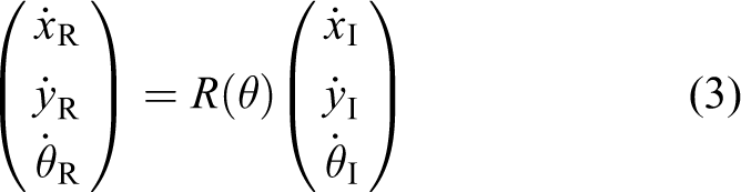
where

The positioning information of the robot can be obtained by using two UWB tags in the posture algorithm. The two tags are installed on both sides of the robot head. The left one is

Schematic diagram of UWB tag installation. UWB: ultrawide band.
Posture of the robot in the global coordinate system
There are four postures for the robot in the global coordinate system, as shown in Figure. 3. The positioning information of the robot in the global coordinate system can be obtained by using the coordinate data

A straight line formed by connecting two tags intersects the

Here

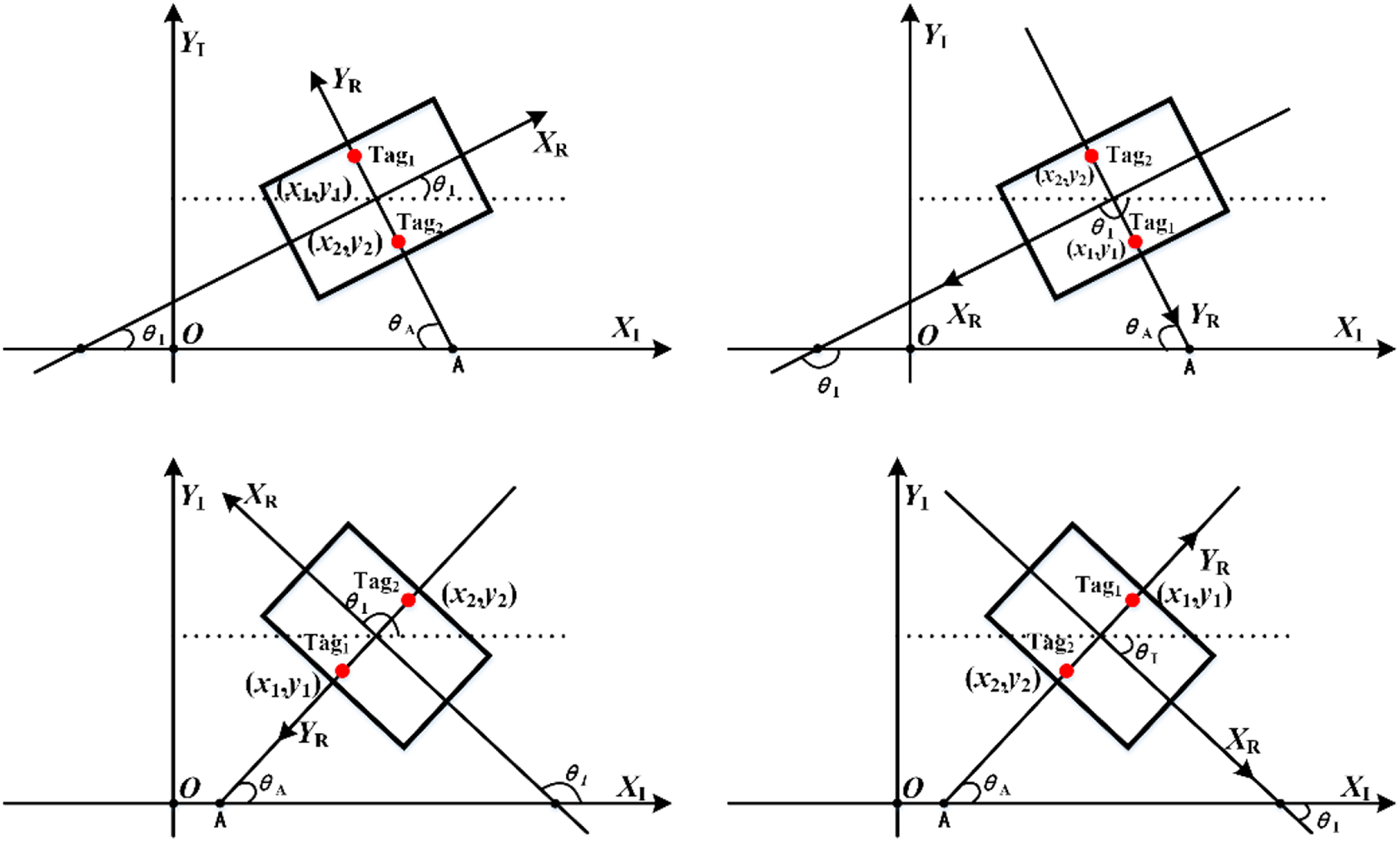
Four postures of the robot in the global coordinate system.
The calculated If If If If
Speed of the robot in the coordinate system
In general, the speed of the robot is measured by the motor encoder. However, the use of the motor encoder results in errors caused by motor slippage. To overcome this problem, we use the positioning information of the two UWB tags of the robot to calculate the speeds of the robot in the global and local coordinate systems.
From equation (5), the positioning information in the
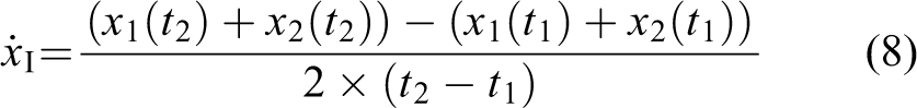
Similarly, the speed of the robot in the

The angle velocity

The speeds of the robot in the global coordinate systems can be rewritten as

Here

Relative posture of the robot and the target
The relative posture of the robot and the target can be represented by
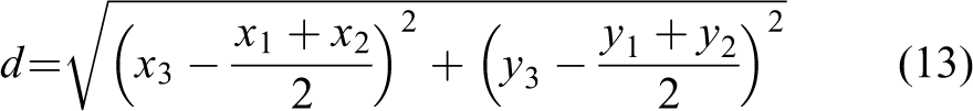
Here x
3 and y
3 are the coordinates of the target point.

So

Therefore, the relative posture of the robot and the target can be given as


The target point is in front of the robot.
If the target is in the opposite direction of the robot as shown in Figure 5, then the relative posture can be obtained similarly, and given as


The target point is behind the robot.
Results and discussion
The analysis shows that the accuracy of the algorithm is closely related to the UWB positioning accuracy that is affected by the measure errors and the position accuracy of the base stations.
27,28
At present, the positioning accuracy has been improved by the researchers, and the simulation error of 2 cm is chosen as the lower limit in this article.
29
We suppose the coordinates of the three base stations are (0,0), (0, 800), and (800, 0); the robot centroid coordinates (400, 400); target point position (800, 800); actual posture angle 45°; and the installation distance of the two tags 60 cm. The posture angle of the robot

Simulated results with different positioning errors: (a) 8 cm, (b) 6 cm, (c) 4 cm, and (d) 2 cm.
Data evaluation under different positioning errors.
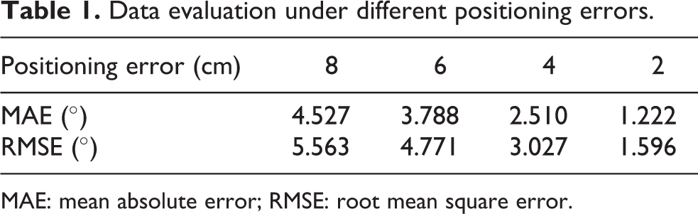
MAE: mean absolute error; RMSE: root mean square error.
We assume that the coordinates of the three base stations are (0,0), (0, 800), and (800, 0); the robot centroid coordinates (400, 400); target point position (800, 800); and the positioning error within 2 cm. The posture angle of the robot

Simulated results with different tag installation distances: (a) 50 cm, (b) 60 cm, (c) 70 cm, and (d) 80 cm. (Inset) The enlarged part of the curves.
Data evaluation under different tag installation distances.

MAE: mean absolute error; RMSE: root mean square error.
To verify the validity of the posture algorithms, the control platform in which the TM32F103-ZET6 is selected as the control core is built to test the robot (Figure 8). The coordinates of the three base stations are (0,0), (0, 800), and (800, 0). The robot is placed at the point (400,400), and the target point is set at (800, 800). The posture angle in the global coordinate system is adjusted to 45° and the installation distance is 24 cm between two tags. The posture data solved by the algorithm are transmitted through Bluetooth. Figure 9 shows the distribution of the experimental posture angles. The results show that the posture angle obtained by the posture algorithm fluctuates around 45°, and the MAE and RMSE are 2.3469° and 2.7093°, respectively. The simulated and experimental trajectories of the robot which moves from the point (400,400) to (800, 800) are shown in Figure 10. Both the simulated and experimental trajectories show good agreement with the ideal trajectory, while from the point (700, 700) to (780, 780) the experimental trajectory cannot fit the ideal trajectory very well. The maximum offset is about 8.26 cm (see the inset). The experimental results are slightly worse than the simulated results because it is difficult to obtain a positioning error of 2 cm for UWB. The results show that the posture data can be obtained accurately by the posture algorithm and the accuracy can meet the requirements of most mobile robots.

Schematic diagram of the robot test.

Distribution of experimental data of global posture angle.

The simulated and experimental trajectories of the robot. (Inset) The enlarged drawing from the point (700, 700) to (780, 780).
Conclusions
A posture algorithm based on UWB is proposed in this article. The posture angle, speed, and other real-time posture data of the mobile robot in the established plane coordinate system can be calculated, and the problems by using IMU can be solved by the posture algorithm. The simulated results show that the posture accuracy increases with the decrease of the positioning errors when the installation distance of the two UWB tags is constant, and the error accuracy increases with the increase of the installation distance of the two UWB tags when the positioning error is within a certain range. Both the simulated and experimental trajectories show good agreement with the ideal trajectory. The results indicate that the posture data can be obtained by the posture algorithm and the accuracy can meet the requirements for most mobile robots. In fact, the accuracy of UWB is influenced by the non-line-of sight blocking, 31 which is not considered in this article. It will be studied in the following work.
Footnotes
Declaration of conflicting interests
The authors declared no potential conflicts of interest with respect to the research, authorship, and/or publication of this article.
Funding
The authors disclosed receipt of the following financial support for the research, authorship and/or publication of this article: This work was funded by the projects of the National Natural Science Foundation of China (No. 62071410 and No. 51502087), the Scientific Research Foundation of Hunan Provincial Department (No. 19A106, No. 20C0498 and No. 21C0581), the Science and Technology Innovation Talents Program of Hunan Province (No. 2021RC1011), and Hunan Graduate Scientific Research Innovation Project (No. CX20201173).