
Abstract
The design of underwater unmanned vehicles is an interdisciplinary study that includes several fields, such as computational fluid dynamics, modeling and control of systems, robotics, image processing, and electronic card design. The operational cost of such vehicles is high because it is dependent on variable fluid properties like salinity and high pressure while its’ mobility must be resistant to environmental conditions such as undersea. The study describes an operating platform, called Lucky Fin, on which the students can develop various control algorithms and can test and extract hydrodynamic parameters of the underwater vehicle. The platform consists of an underwater vehicle and two testing tanks. The control card, the user control program interface, and a manipulator’s arm are designed to be used for a series of control applications such as depth, heading, target tracking, and capturing. The results of several tests are illustrated in this article.
Keywords
Introduction
Underwater vehicles (UVs) perform several tasks, such as diving to the desired depth, docking under demanding conditions, and visual inspection of specific underwater structures 1 while keeping the heading angle tangent to the desired trajectory. An experimental environment can be set up to facilitate the development of different control methods, which result in reasonable performances. For this purpose, Miorim et al. 2 have developed an educational tool for remotely operated vehicles (ROVs). They have extracted the requirements of a control center for educational purposes, which provides different high sea ROV operations. Fletcher and Harris 3 developed a virtual environment (VE) system for training the piloting skills on ROVs. The VE system contains some mission operations including maneuvering, integration of sensor data, and situational awareness. Eng et al. 4 prepared a method for online identification of autonomous underwater vehicle (AUV) dynamics in field experiments. They use the models to estimate the maneuvering radius of the AUV at altered speeds and to design an optimized gain controller.
On the other hand, Wang et al. 5 have developed an AUV platform that carries a laser line scanner to maintain an accurate and stable altitude. For doing this, the vertical thrusters are operated around the zero point, and the direction of the thrusters has been altered frequently. There are several competitions for ROVs and AUVs in which groups of students participate. These competitions encourage students to develop and share new skills in underwater technology and related applications. For this purpose, a depth control system has been developed for a microprocessor-based UV. 6 The depth information obtained by the pressure sensor is compared with the desired depth, and the error is eliminated by means of controlling vertical motors. DeBitetto 7 has used fuzzy controllers instead of traditional control methods in a similar study. The pitch angle is controlled using depth error information and its’ derivative. In the mentioned study, the error and its’ derivative are described by verbal variables, and each variable is separated into fuzzy membership functions (MFs).
Using the sliding mode observer and Kalman Filter, Kim and Shin 8 have determined the hydrodynamic coefficients of a vehicle with six degrees of freedom (DOF). They have extracted the block diagram model of the vehicle and have simulated its behavior of various reference depth and direction values. In these studies, various models related to the applications are used as UV models. Some of these UVs are cable-connected and ROVs, while the other groups are AUVs. The vehicles in the latter groups usually communicate with the surface system by means of acoustic modems. Both traditional 9 and novel 10,11 control techniques are applied to provide autonomous motion for UVs. Fernandes et al. 12 have managed to control a UV in four DOFs (yaw, sway, surge, and heave), and they have designed a controller to track an appropriate and smooth reference path with an unmodelled plant dynamics, the varying UV parameters, and the existence of environmental noise and disturbances. Image acquisition from UVs, acoustic transmission, and image processing are also significant subjects in this field. In a case study, images acquired from the UV are improved using Canny edge detection, Hue, Luma, and Saturation algorithms. 13 AUVs are generally equipped with at least one optical camera to acquire visual information about underwater locations. It is also essential for the estimation of AUV position based on the target of underwater objects. 14 Object tracking algorithms are used in many different areas, such as security systems, autonomous vehicles, robots, and traffic cameras. The common point is the defining and updating of the position of image frames in a video. 15
Traditional parameter estimation methods, which have been used to improve UV hydrodynamics, are towing experiments and pool tests. Building and operating towing tests for real size vehicles are quite an expensive method. 9 These experiments give very realistic results when vehicle sensors are sensitive. However, changing flow conditions in experimental studies make it difficult to get reasonable and precise results. Experimental studies on the determination of UV hydrodynamics require such a long period that lose time for research and development processes. Computational fluid dynamics (CFD) is an effective computer simulation and design method for determining hydrodynamic model parameters of UUVs. Therefore, the usage of computers and the CFD has been emphasized. The hydrodynamic behavior of a vehicle could be extracted by fluid dynamic imaging and simulations of the CFD. 16 In a case study, the mathematical model of a low-speed AUV was extracted by means of CFD analysis for two critical hydrodynamic parameters, which are added mass (MA ) and damping matrices. 17
The mechanical, electronic, and software designs of a UV test platform (TP), which has been developed by the Kocaeli University Electronics and Telecommunications Department between 2013 and 2020 and is called the Lucky Fin Project, are introduced in this study. The platform is composed of UV and lateral and vertical test tanks. Although the basic concepts are preserved, sensors, cameras, battery types, microcontrollers, and card designs have been modified in line with the development stages. Basic movements, such as diving, keeping the desired depth level or position angle, and tracking–grasping a target object, are provided by control systems. To achieve this kind of robust autonomy, the kinematic and the dynamic behaviors of the vehicle should also be determined and modeled. P (proportional), PD (proportional–derivative), PID (proportional–integral–derivative), and ANFIS (adaptive neuro-fuzzy inference system) based controllers, which can respond to the desired commands within certain performance criteria, have been developed and tested on the platform. Some actual system parameters are identified and adjusted to improve the design. As the platform serves as a testbed for a set of experiments, the electronics and telecommunication engineering students can develop applications on a wide range of topics that they have learned during the lectures. Depth and heading control applications of the UV have been carried out and interpreted in the laboratory tests. In addition, image processing tests on target tracking and object capturing operations are also included. UV itself measures some parameters, such as orientations and corresponding velocities, referring to the body frame. These values should be converted by the kinematic model and interpreted into the Earth Fixed parameters of the shore computer. Some of the UV dynamic parameters are determined according to the simulations and experimental tests.
The study considers the benefits and contributions of designing a framework, Lucky Fin, for educational purposes UV development and testing. In doing so, it was inspired by some guiding works. Modest improvements and contributions are made to some of these studies in terms of equipment, design, and method, and the experimental setup emerged. An underwater robot experimental testbed was developed for depth control and temperature measurement. 18 A piston actuator moves up and down to adjust the sinking level of the robot in a glass rectangular aquarium tank. The piston as an actuator has a deadzone and deadband nonlinearity, which causes errors, oscillations, and instability. Accurate measurement takes 3 min, and 60 cm depth is reached by 1.55 cm deviations. The Lucky Fin Project was influenced by the principle of this work and aimed to improve it. The mechanical design of the passive diving robot, which consists of a tube and a piston, has been replaced by a UV with four DOFs, propellant motors, a camera, and sensorial equipment. Heave-surge and roll-heading movements are applied in cylinder-shaped horizontal and lateral tanks, respectively. More accurate depth control is achieved as given in the “Discussions on UV control applications” section. Various control methods have been proposed in the literature over the years. Sliding mode controllers (SMCs) are the common heading, depth, pitch, and yaw control methods applied to AUV systems. 19,20 Non-linear characteristics of thruster brushless motors with a dead zone result in heading error. When the error goes beyond a definite rate, the controller’s effort to adjust it as a step disturbance and overshoots in the transient response could reach around five degrees. 21 Unmeasurable conditions, sensory noise, electromagnetic effects, and signal delays also degrade the stability and performance of the AUV heading control. 22 The high performance and high accelerations of brushless motors are of course indisputable. However, the motor driver design of Lucky Fin provided slower but precise and stable responses of DC motors within narrow angular ranges. A highly precise calibrated TCM3 electronic compass is water tightly insulated and located at the top of the vehicle. This location is outside of the electronic control hull and is away from the power layer and metal parts (Figure 9(b)). These adjustments let the vehicle less susceptible to electromagnetic disturbances and provide precise control of Euler angles. Vision-based positioning and tracking of an AUV have been used successfully in clean environments under restricted distances. 23 Specifically, AUVs equipped with robotic arm manipulators could execute high-resolution computer vision-based tasks, such as detecting and capturing objects within reachable distances of the manipulator. 24 Image processing algorithms are addressed in real-time underwater visual tracking operations. Hough algorithm proposed for localization operations increases recognition capability on pipelines. 25 Computational intelligence methods, such as artificial neural network based adaptive control systems, fuzzy cerebella model articulation controller, 11 and self-adaptive recurrent neuro-fuzzy control 10 methods, improve tracking performance and dynamic motion response of AUVs. Lucky Fin’s object tracking task is accomplished with vision-based direction and surge control. While PD and ANFIS algorithms are performed for the mentioned control operations, the Hough algorithm is used for object detection. Autonomous systems consisting of a UV and a robot arm (RA) are designed to track underwater objects and detect their positions precisely. The object is detected by image processing, and the manipulator approaches the object with methods such as fuzzy control. 26 Some manipulators are controlled manually, 27 and in others, the object is captured with a fixed arm 24 or by hovering and vacuuming the object. 28 In this study, image processing and axial control algorithms are prepared on Raspberry Pi for detecting an object from the camera and capturing it with a manipulator. The mobility of the manipulator increases the DOF of Lucky Fin by two degrees and provides more flexible approach conditions to the object. The control card (CC) and software are original and open to development. CFD is a convenient method for parameter extraction of the UUV hydrodynamic model. 29 Control of movements in low speeds, such as sway, heave, surge, and heading, can be precisely modeled and simulated in terms of hydrodynamic coefficients, such as added mass (MA ), drag (CD ), lifting (CL ), and controller parameters. The combination of CFD simulation with free streaming turbulence models and experimental tests improves parameter identification. 30 However, confirmation of the hydrodynamic parameters obtained in the simulations with experimental tests is rare in the literature. Lucky Fin is a particular designed modular type of UV that has four DOF, and the relevant computer-aided design (CAD) model is extracted for the first time. Cost-effective confirmatory experimental methods that are worthy of reference in testing complex-shaped modular UVs are included in the study.
Overview of the UV TP
For the mentioned control purposes, a TP consisting of a UV, CC, a control program interface (CPI) software, and two simulation tanks was designed and implemented (Figure 1). Depth is measured by a high-precision pressure sensor where heading is determined by a three-axis electronic compass. The depth and heading control applications are applied in the horizontal tank (Figure 1(a)) and lateral tank (Figure 1(b)), respectively.

(a) Depth and (b) heading control applications in the TP. TP: test platform.
The CC in the UV and the CPI on the computer utilize the Universal Synchronous/Asynchronous Receiver Transmitter (USART) communication protocol. A CCD camera is set on the UV for monitoring and image processing. The CC drives two vertical, and two horizontal thrusters and optionally servomotors of a three DOF manipulator. Principally, the CC is designed for both remote and autonomous control applications. Thus, the CC operates the vehicle as an open or a closed-loop control system. In open-loop mode, control commands sent by the operator via the CPI are transmitted to the vehicle’s actuators, and data from the sensor are monitored on the CPI. The closed-loop processes the sensory data and produces the control signals. Features of the vehicle are given in Table 1.
UV features.

UV: underwater vehicle.
Methods used in the UV system design
Kinematic modeling of the UV
The position and orientation of vehicles on three axes are calculated according to the kinematic model of the vehicle. Orientations measured by the TCM3 electronic compass in the vehicle should be converted by the Jacobian Matrix to be interpreted by the operator located next to the shore computer. The pulse width modulation (PWM) value of each motor is determined by referring to its’ target axes. These equations are utilized in both three-dimensional model simulations by means of Matlab, and the equations are embedded into the CPI software for online orientation control applications. The most used kinematic equations are Euler angles and quadrature groups in these applications. 31
Euler angles. The origin of the UV coordinate system is returned until it is matched with the earth coordinate system’s origin

Illustration of the Lucky Fin UV elementary motions and frames on the 3D model. UV: underwater vehicle; 3D: three-dimensional.
A compact representation of the Jacobian matrix for the kinematic equations is written as

J 1 and J 2 are given in (2)

where c, s, and t are abbreviations of cosine, sine, and tangent, respectively. The Jacobian matrix matches the Cartesian position vector with the angular Euler vector, which is given in terms of SNAME 32

where

The kinematic transformation of linear and angular velocities between local and earth coordinate systems are given as

These variables are determined according to the earth coordinate system. In this case, the velocities of the UV are known and represented as the forward kinematic equation.
Dynamic modeling of the UV
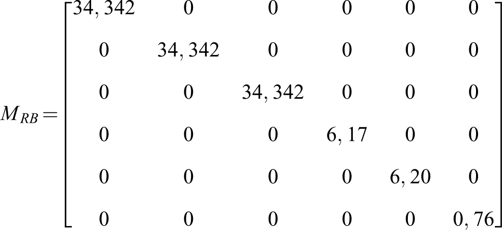
Dynamic modeling deals with the relationship between the robot’s resulting motion and the forces applied to the robot. 33 UUV dynamics are derived from the Newton–Euler equation of a rigid body in a liquid

where

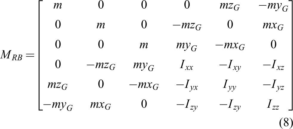


When we apply forces on the x-, y-, and z-axes and moments around these axes to a vehicle, the water masses that need to be pushed resist the vehicle in these directions. Each element of the

Terms of

Control methods
PD and on–off methods
These methods are used for individual depth, roll, yaw, and heading control applications. The control output,

where Kp and Kd are proportional and derivative coefficients of the error, respectively. 37 The PD control routine includes numerical representations of the error, integral, and derivation
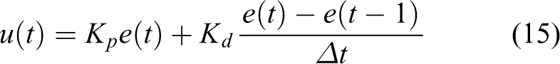
where
On the other hand, on–off control is a basic feedback system that switches the actuator from fully closed to fully open according to the setpoint of the variable being controlled. In such controllers, a dead band between the lower border (lb) and upper border (ub) can be placed to prevent chattering around a set-point

ANFIS method
ANFIS is a structure that is a combination of a Sugeno-type fuzzy system with neural learning capability (Figure 3). Such an approach makes fuzzy logic more systematic and less dependent on experience. ANFIS calculates inputs in a forward direction by means of fuzzification, production, normalization, and defuzzification layers and propagates back the resultant error to the MF parameters. 38
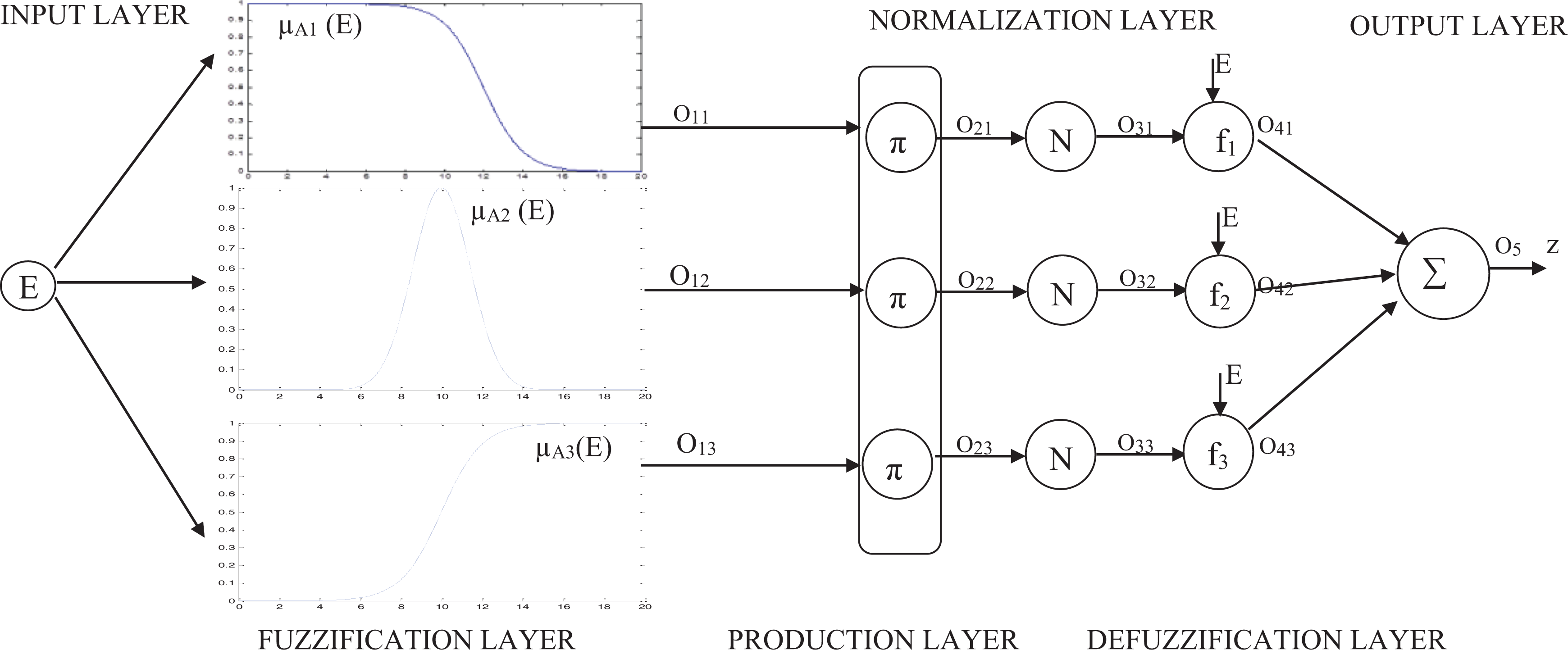
ANFIS model with three rules. ANFIS: adaptive neuro-fuzzy inference system.
Backpropagation method is utilized for adapting the MF parameters, which provide the ANFIS model to learn the input–output characteristics of a system. 39
Four DOF Lucky Fin UV model
The Earth (E) fixed frame and the local axes that the vehicle can move are shown in Figure 4. If the horizontal thrusters run at identical velocities, the UV will move in the x-direction. When the same thrusters operated at different velocities, they will rotate around the z-axis with an angular velocity (r) and an angular displacement (ψ). When the vertical thrusters of the vehicle run at identical velocities, it dives in the z-direction. When it operates at different velocities or in opposite directions, it rotates around the x-axis with its angular velocity (p) and an angular displacement (φ). The highest velocities obtained by the Lucky Fin vehicle during the experimental studies are given in Table 2.

The four DOF Lucky Fin UV: earth fixed frame and body fixed frame. DOF: degrees of freedom; UV: underwater vehicle.
Motion axes of four DOF Lucky Fin UV and the highest speeds obtained from the vehicle.
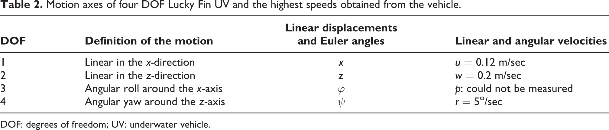
DOF: degrees of freedom; UV: underwater vehicle.
Image processing and target tracking methods for robot vision systems
After starting image processing applications, the analog camera used in the early days of UV design was replaced by the digital Raspberry Pi Camera. OpenCV is a computer vision open-source library of Intel, which provides a high level of algorithms and functions for robot vision problems. 40 red, blue, and green (RGB) and hue saturation value (HSV) models that are suitable for the OpenCV format could be used. The minimum and maximum values of the color can be obtained during the conversion process from RGB space to HSV space. Hough circle transform is a method widely used in image processing to detect circular shapes where many applications, such as eye recognition, license plate detection, the ball finding on the football field, can be done. 41 With this method, shapes are determined as follows: edges of the image are detected, and the image is converted into binary. Edge pixels are voted on the accumulator. According to the result of the accumulator, the shapes with the highest votes are more likely to be found in the image. The detected geometric shapes can be displayed as an output of the image. As an example, a green circle is drawn when a red object is detected (Figure 5).

Object detection by means of the Hough method.
Since circular shapes are expected to form in the image, the accumulator array consists of the center points (a, b) of the circle and the radius value (r). Equation (17) illustrates the central circle formula. Positions x and y are given in (18) and (19), respectively.


Once the angle is valued between 0 and 2π, it can be determined whether a point is on the circle or not. The circle with the highest number of voted values in the accumulator is drawn. Following the image has been processed, the thruster velocities should be adjusted proportionally according to the position of the object. If we consider the vehicle camera window where the image is shown as the x–y coordinate plane: The velocities of the thrusters should vary continuously referring to the y-axis of the window. If the target object is on the right or on the left of the y-axis, left or right thrusters should run faster, respectively (Figure 6).

Position of an object refers to the y-axis of the UV. UV: underwater vehicle.
In order to change the speed of the motors, the PWM signals generated on the controller card should be sent to the motors. 42
UV and manipulator systems for object capturing operations
The integration of the UV and the RA(UV + RA) has facilitated operations, such as repairing oil platforms, detecting and welding leaks of pipelines, collecting underwater objects, and investigating deeply submerged wrecks. 32 Images of underwater objects can be sent to the operator on land. The operator’s arm movement could be detected by image processing methods, matched with the angle movements in the manipulator’s joints, and consequently, the object is grasped. 43 Seashells could be detected at a depth of 100 m using image processing methods and be collected by the vacuum system of a fixed arm mounted on the vehicle. 28 One of the educational experiment designs in this study is deal with RA applications. 44 Detecting an object from the camera on UV + RA and capturing the process of the target object are carried out by means of image processing and axial control algorithms. The UV + RA was also used in an ROV competition. The manipulator ideally provides two more DOF to the UV, and consequently, conditions for approaching the object would be more flexible (Figure 7).
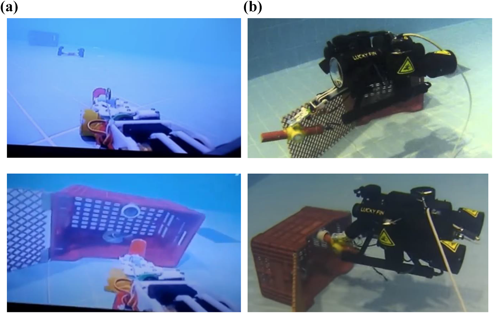
Underwater tests of the Lucky Fin UV + RA system, Kocaeli University Indoor Swimming Pool. (a) RA view from UV indoor camera and (b) uutdoor camera shots. UV: underwater vehicle; RA: robot arm.
Electronic equipment and software designs
Controller card (CC) design
The developed UV CC includes two microcontrollers (μC), which are ARM Cortex M4 based STM32F407VGT6 (STM32) μC and a BeagleBone Black development card. The BeagleBone hosts an Arm Cortex-A8-based μC. According to the applications, these two microprocessors share the tasks (Figure 8). In the later studies, BeagleBone Black is replaced with Raspberry Pi minicomputer. 45

Top view of the designed CC and locations of the main equipment. CC: control card.
The CC is designed to be powered by a 12 Volt battery pack. The supply voltage is reduced by the switched-mode converters till the required levels of the microcontrollers and the sensors. A 12 V SEPIC battery charging unit is added to the card. The STM32 μC undertakes the tasks such as the PD control process by means of the sensors and thrusters and commands of on–off switches of the lightning and the camera. TCM3 electronic compass, GY-80 inertial movement unit (IMU), and WIKA S10 pressure sensor are used to acquire direction, velocity, and depth data, respectively. The pressure sensor and electronic compass are set under and upper parts of the UV, respectively (Figure 9).

(a) Pressure sensor and (b) electronic compass.
For instance, the calculation of the depth data by the CC is given as follows

where ADC is analog to digital conversion data of the measured pressure. In the later stages, the analog WIKA S10 sensor is replaced with a digital BAR 30 depth sensor. The μC uses the data from compass and IMU sensors as feedback while it sends the processed data to either the BeagleBone Black card or the control interface directly. The CC is designed to control up to 8 DC and 8 servo motors for thrusters and manipulators. Servo motors can directly be driven by PWM outputs of the μC. The reserved outputs to servo motors are used for electronic speed controllers of the applications, such as brushless DC motors, which require high power. H-Bridge drivers are designed to control the speed and direction of the DC motors. The USART, I2C, and 1-Wire communication protocols are implemented for communication among the microcontrollers, sensors, and the interface. The USART protocol allows long-distance communications at low speeds, whereas the I2C protocol allows fast data transmissions (Figure 10).

General task schematic of the CC. CC: control card.
The CC contains four USART lines, and one of them is between TCM3 and STM32. The others are the CPI—STM32, BeagleBone (BB)—STM32, and BB—CPI.
The CPI
The CPI, which is written in C # programming language, is a computer user interface that interacts with the vehicle’s hardware and allows for monitoring and controlling of the UV both in manual and automatic modes. In the manual mode, the orientation of the vehicle is manipulated either by graphical CPI buttons or by a keyboard. The CPI can capture images and video, acquire data, and plot the status graphics of the UV (Figure 11).

The CPI of the UV. CPI: control program interface; UV: underwater vehicle.
CPI supports USB cameras. However, as the cable distance between the computer and the UV is not close enough, the image is transferred analog through the coaxial line of a non-buoyant cable. The received analog video image is converted to digital by means of a USB image capturing device. Since the CPI initializes communication with the vehicle, it starts to record the vehicle data into a database file labeled with the date and time information. The CPI includes the option to monitor, graph and report recorded data, such as pitch, yaw, depth, heading, supply voltage, motor currents, and controller output.
Discussions on UV control applications
Some experiments are introduced in practice for educational purposes in the designed development platform. The on–off, PD, PID, and ANFIS control algorithms for depth and heading control applications are prepared and uploaded to the STM32 μC.
Depth control tests
The depth control application is completed by means of the PD method, whose parameters are defined by trial and fault. The step response of the UV to a 40 cm set value as the required depth is given in Figure 12.

Step response of the UV depth control system. 46 UV: underwater vehicle.
While the thruster’s current load influences the supply voltage (12 V) of the analog pressure sensor, ripples are observed in the depth graphic. Their supplies are separated in the latter CC versions. The UV dived from 10 cm (around the surface) to 40 cm depth in 6.7s. Percent maximum overshoot (%MO) is %17. Settling time (ts
) is around 12.3s. A considerable steady-state error (
Transient state analysis of the depth control response.

PD: proportional–derivative; MO: maximum overshoot.
Heading control tests
The lateral pool is engaged to the TP for heading (yaw) control application. Digital electronic compass (TCM3) and horizontal thrusters are used for the feedback and actuation, respectively. Within the heading control experiment, the UV is subjected to on–off and PD control tests (Figure 13).

On–off and PD time responses of the heading control application. 47 PD: proportional–derivative.
In the initial phase of the test, the UV was positioned +50° clockwise from the north. It is subjected to a shifting effect to the left or right side around 10° and is expected to return to the set value. In the on–off control test, the UV had oscillations (overshoots and undershoots) around and has not settled to the reference value. For this reason, measuring of ts
and
Performance comparison for transient state analysis of the heading control.

PD: proportional–derivative; MO: maximum overshoot.
Consequently, the PD controller performed better than the on–off controller.
Image processing for object tracking system
Analog camera and BeagleBone Black minicomputer are replaced with Rasberry Pi camera and Raspberry minicomputer, respectively. UV control applications are carried out by the appropriate image processing methods: Imutils, PIRGBarray, Deque, Argparse, RPI.GPIO, time, CV2, and NumPy Libraries are utilized in a series of tasks, such as camera interface, masking, object tracking, production of PWM data, image processing, various kind of functions, and storing huge sizes of position data and RGB data in arrays. Within the scope of this application, the position changes in circular objects are determined by using the “Hough transformation” method and the tracking process implemented according to this position. 41 The largest contour is determined after masking and enclosing the object center. A line is drawn between the origin of the UV camera and the central coordinates of the object. Then, the radius of the target is calculated by finding the inner side of the circle. If the diameter of this circle we have found falls down a certain value, horizontal thruster motors run proportionally. The control signal is a function of E both in P and ANFIS methods

Proportional (P) control method
The control signal (U) proportional (

A further object moves from the origin, and more errors occur. According to this error, if the object is on the right side, the speed of the left horizontal thruster proportionally increases, and the speed of the right horizontal thruster decreases. Contrariwise, the opposite situation is true for the left side. E is determined to refer to the difference between the central position coordinates of the object and the origin of the vehicle camera (Figure 14).

Distance error calculated refers to the center coordinates of the object.
ANFIS control method
ANFIS has one input (E) and one output (U) with three rules, where E is the deviation from the origin of the Lucky Fin Camera in the x-axis

While Table 5 is designed to demonstrate heading control, the basic rules for surge control are similar.
Fuzzy rules of ANFIS.

ANFIS: adaptive neuro-fuzzy inference system; PWM: pulse width modulation.
The model is trained and tested referring to 37 training data and 20 testing data, respectively. The data indicate a linear relationship between heading deviation [−275, 0, +275] and motor drive PWM ratios [−100, 0, +100]. However, a camera lens is monitoring the deviation larger at the center and smaller than it should be at the corners. In addition, the left motor stops under 20% PWM, and the torque of the right motor is slightly strong (around 2%) for identical PWM values around zero grade. For this reason, the data set is improved by several tries and faults (Figure 15).

(a) Training and (b) testing responses for the trained FIS model for 10000 iterations. FIS: fuzzy inference system.
Negative outputs proportionally activate the left motor in the forward direction and the right motor in the reverse direction. In a contrariwise situation, the opposite operation is true. Trained MFs of E are given in Figure 16. Singleton MFs TL, S, and R are located on −275,0. and +275 of output variable U.

Trained input variable E.
Related input is fuzzified using Gauss MFs according to trained parameters

Here, c and σ are the parameters that determine the center and width of the Gaussian Curve, respectively. 48 Fuzzy inference system is executed to refer to fuzzification, production, normalization, and defuzzification processes (Figure 3). ANFIS functions, which are operated in each layer, can be extracted by programming codes step by step. 38 Execution of fuzzy rules for an example input, E = −146 pixels, are illustrated in Figure A1.
According to E, the motor direction and the PWM ratio applied to the motors are adjusted. Out-of-water tests validate the vehicle’s response to the object with the appropriate PWM values. The values captured by the camera are transferred to the computer via Wi-Fi (Figure A2), and the underwater tests of the UV were successfully accomplished. The vehicle is computer-controlled and able to move autonomously by the CC. As a result of these operations, the image of the object in the camera is shown in Figure 17. The location information output by writing the line of code is as follows
$ python3 object_tracker.py


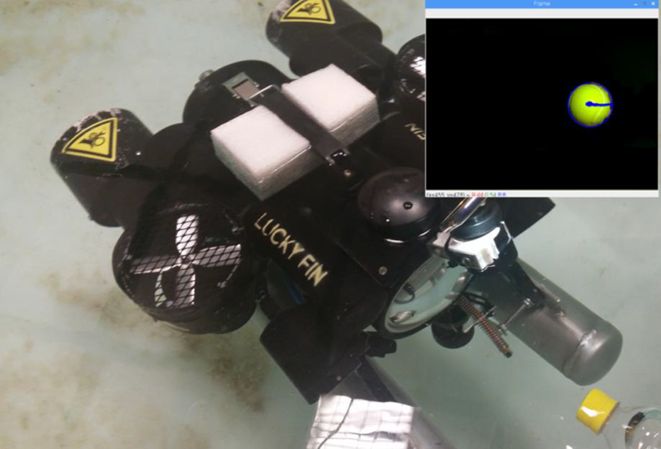
Object tracking in tests.
This output means that the radius of the target is reported as 44 pixels to the frame interface and the center coordinates of the target are N (x, y) = (455, 478) (Figure 17). The related control algorithm is given in Figure A3. The object tracking program controls two parameters: Heading control refers to deflection E from the target, and surge control refers to distance E from the target. PWM rates of motors reacting to the E signals are the same for both control procedures. The direction of rotation is identical for surge control but reverse for heading control. Experimental results of the heading control tests for PID and ANFIS methods are given in Figure 18. 49

Heading control test results: PID and ANFIS control responses to the −20 pixels deflection (E). PID: proportional–integral–derivative; ANFIS: adaptive neuro-fuzzy inference system.
Feedback control by the image process, in general, reduces E, and reasonable results have been achieved for object tracking operations. The controller settles the UV to the direction of a target under 3.5s for both methods (Table 6).
Performance comparison of visual-based P and ANFIS heading control.

ANFIS: adaptive neuro-fuzzy inference system; MO: maximum overshoot.
The maximum overshoot in the ANFIS control is lower than in the PID control. In addition, the settling is achieved earlier in the ANFIS control than in the PID control.
Image processing tests for the UV + manipulator object capturing system
OpenCV and real-time image processing libraries are installed on Raspberry Pi. The application is started with the detection of coordinate points of the object and end effector in the image and the calculation of the distance between them. The distance is calculated on a pixel basis on the two-dimensional image space and is converted to cm. The image captured by the camera is in RGB space and is transformed into HSV space. The object and the end effector of the manipulator RA are labeled in blue and red colors, respectively. Threshold values of red and blue colors in HSV color space have been already determined in the image. Original and thresholded images are shown in Figure 19.

Positions of the object (blue) and end effector (red) in the original images and after the thresholding process. 44
The coordinates of the end effector and the target object are determined and used to drive the motors. Pixel distance between two points,

Considering the x-axis, the coordinate of the end effector marked in red is x
1 and the coordinate of the target marked in blue is x
2, where y
1 and y
2 are the coordinates of the end effector and target along the y-axis, respectively. The camera feedbacks the

Approaching distance,
Tests for estimation of some dynamic parameters
Hydrodynamic effects resulting from the movement of the Lucky Fin UV and M matrix parameters of the UV dynamic mathematical model are examined both in simulation and experimental tests. The results are insufficient; however, they will lead to constructing proper test setups for the future determination of full dynamic parameters of the Lucky Fin. In this application, CFD analysis is addressed to determine

(a) Vehicle body mesh structure and (b) example CFD analysis response of Lucky Fin to liquid flow in the x (surge) direction. CFD: computational fluid dynamics.
Some tests of Lucky Fin were conducted by the TPs in the Electronics and Telecommunication Engineering Department of Kocaeli University. Two different forces (9 N and 4 N, respectively) are applied to the UV in the first half and second half of the surging movement. Corresponding accelerations are measured as


Conclusion and future works
A UV platform is designed to utilize for research and development purposes in Kocaeli University Engineering Faculty. Students have implemented their projects and combined their theories with applications of the concepts, which are taught in the Department of Electronics and Telecommunication Engineering. The modeling and design phases of the UV platform are given, followed by some experimental developments that illustrate the transition efforts to autonomy.
However, the primary purpose of the experiments did not focus on optimization. Students can develop novel methods on the platform. For instance, a student group from Kocaeli University has developed a two-axis arm manipulator, which has been attached to the UV. The UV with manipulator system is joined to the MATE-ROV 2016 International Competition. A student group developed image processing applications on which the UV tracked an object, where ANFIS and PID heading control methods are used. In these studies, the performance of the ANFIS control method was higher than the PID control method.
UV is planned to be put into practice in several half autonomy applications, such as line tracking, path planning and tracking, diving buddy (diving assistance), teleoperations, and inspection of environmental pollution in receiving water bodies in future works. By means of the TP, a series of force–moment tests could be applied to the UV. This will result in finding the hydrodynamic parameters of a vehicle. These parameters would allow simulations of CFD Programs. 16 Dynamic model of a low-speed UV could be obtained by means of CFD analysis. 17 UV measures some parameters, such as orientations and corresponding velocities referring to the body frame. These values should be converted by the kinematic model and interpreted into the Earth Fixed parameters of the shore computer. Some of the UV dynamic parameters are determined according to simulations and experimental tests.
Onboard CC design, algorithms developed for depth, heading, target tracking, grasping control and image processing, kinematic and dynamic modeling for future simulation, and controller optimization studies bring about partial autonomy to conventional ROVs.
Supplemental material
Supplemental Material, sj-pdf-1-arx-10.1177_17298806221103710 - Development stages of a semi-autonomous underwater vehicle experiment platform
Supplemental Material, sj-pdf-1-arx-10.1177_17298806221103710 for Development stages of a semi-autonomous underwater vehicle experiment platform by YILMAZ Serhat in International Journal of Advanced Robotic Systems
Footnotes
APPENDIX
Acknowledgment
The author would like to thank Ayako Tajima for her contribution.
Declaration of conflicting interests
The author(s) declared no potential conflicts of interest with respect to the research, authorship, and/or publication of this article.
Funding
The author(s) received no financial support for the research, authorship, and/or publication of this article.
Supplemental material
Supplemental material for this article is available online.
References
Supplementary Material
Please find the following supplemental material available below.
For Open Access articles published under a Creative Commons License, all supplemental material carries the same license as the article it is associated with.
For non-Open Access articles published, all supplemental material carries a non-exclusive license, and permission requests for re-use of supplemental material or any part of supplemental material shall be sent directly to the copyright owner as specified in the copyright notice associated with the article.