
Abstract
The horizontal thrusters located as X shape is a commonly used configuration in remotely operated underwater vehicle (ROV). To improve the motion performance of the remotely operated underwater vehicle with this configuration for some typical operation tasks, a multistep thrust allocation method based on priority idea is proposed. Firstly, the thrust allocation result of every single force/moment among the horizontal thrusters is obtained by using a piecewise calculation method. Then, a thrust allocation function of multiple forces and moment is constructed, transforming the thrust allocation problem into a multiparameter optimization problem. The objective function of the optimization problem is established based on priority idea, and limits of the thrusters are considered as constraints. Finally, a thrust redistribution method is adopted in order to further utilize the unsaturated thrusters in the propulsion system. Simulation results show that the proposed thrust allocation method has various advantages over the pseudo-inverse method, which makes the remotely operated underwater vehicle perform perfectly in the given operation task. The proposed method has important practical value and application prospects.
Introduction
Remotely operated underwater vehicle (ROV) has been widely used in oceanographic mapping, marine resources development, deep-sea salvage operation, nuclear power plant detection, and other fields because of its good adaptability, flexible movement, and strong operation ability. 1,2 ROV is usually equipped with several thrusters. The control system in the ROV realizes the multi-degree-of-freedom (m-DoF) motion control by adjusting the speed of the thrusters. Thrust allocation is one of the key modules in the control system. Its primary objective is to provide a set of commands for the thrusters reasonably so that the actual forces and moments generated by the propulsion system can meet the desired forces and moments calculated by the control algorithm. 3 Generally, ROV is designed as an over-actuated system, that is, the number of thrusters in its propulsion system is more than the DoFs to be controlled. 4 As a consequence, there are multiple combinations of thrust that can match the requirements. Then, how to select the optimal one is a complex mathematical problem.
Thrust allocation problem also exists in other equipment such as surface dynamic positioning vessels, 5 unmanned aerial vehicles, 6 and spacecrafts. 7 Over the past decades, the development of thrust allocation method has undergone a process from simple to complex, as well as from single objective optimization to multi-objective optimization. 8,9 A variety of thrust allocation methods have been proposed and verified. Among them, direct allocation and pseudo-inverse were proposed in the earlier time. Both of them have the advantages of simple calculation and high real-time performance. In fact, the pseudo-inverse method has been used more widely. Johansen and Fossen 10 realized the thrust allocation for marine vehicles based on the pseudo-inverse method, and Lang and de Ruiter 11 applied the pseudo-inverse method to distribute the forces and moments of a spacecraft. However, the physical constraints of thrusters are not considered in the pseudo-inverse method. The solution obtained by this method may be beyond the capability of thrusters, resulting in the problem of oversaturation. Many improved methods have been proposed to achieve better performance. Normalization process of inputs is a convenient method to avoid the oversaturation of thrusters, but this method also reduces the utilization rate of the propulsion system. By comparison, redistribution pseudo-inverse method 12,13 and cascade pseudo-inverse method 14 are more superior solutions for dealing with the oversaturation case, which use linear programming to realize the secondary allocation and optimization. Ye et al. 15 introduced a weight matrix into the pseudo-inverse method, which can minimize the energy consumption of the propulsion system under many restricted conditions. Furthermore, the pseudo-inverse method with weight matrix can be used for fault-tolerant control according to the status of the propulsion system. 16,17
Compared with the pseudo-inverse method, the quadratic programming (QP) method is more complicated, reliable, and suitable for a wider range of occasions. It has been widely used to solve the thrust allocation problem of thrusters with linear constraints such as limit of speed acceleration and azimuth rate. 18,19 Conversely, the QP method is not applicable to the propulsion system with rudders and other special thrusters, since the thrust allocation problem becomes a nonconvex nonlinear optimization problem. For these cases, Witkowska and Smierzchalski 20 and Johansen et al. 21 adopted the sequential quadratic programming (SQP) method to solve the thrust allocation problem with nonlinear constraints successfully. The SQP method relies much on the initial value, which means it gets different optimization results from different initial value, and is difficult to obtain global convergence. To enhance the global searching ability, Li and Yang 22 combined SQP with multi-start mechanism method, which runs the SQP solver from various initial points concurrently to get various solutions, and the final minimal value can be selected. However, the multi-start mechanism method obtains high accuracy of solution by sacrificing efficiency. Another disadvantage of the SQP method is that the existence of local minima introduces discontinuities in the command signals of thrusters even if the desired forces are continuous. Lindegaard and Fossen 23 proposed a three-step allocation method to produce continuous solution for avoiding excessive wear on the propulsion system. For symmetrical double-ended ferries, Torben et al. 24 used thrust configuration constraint to reduce the solution space of the nonlinear thrust allocation problem, which achieves better real-time performance than the SQP method.
Recently, many intelligent optimization algorithms such as genetic algorithm, 25 bee colony algorithm, 26 particle swarm optimization algorithm, 27 harmony search algorithm, 28 and reinforcement learning algorithm 29 have been used to solve the thrust allocation problem. These methods have no restriction to the objective function and constraints of the optimization problem and can obtain high accuracy solutions easily. They are suitable for solving complex nonlinear optimization problems established by considering many factors, such as physical limits of thrusters, singularity of the propulsion system, previous status, security restrictions, and power supply. Obviously, the common drawbacks of intelligent optimization algorithms are difficult implementation, large-scale calculation, time-consuming and high requirement of processor.
Besides considering the parameters of the propulsion system in the design of thrust allocation method, characteristics of other systems and external information should also be adopted to achieve better performance of the whole equipment. It is known that hydrodynamic interactions like thruster–hull interaction, thruster–current interaction, and thruster–thruster interaction exist in most marine vehicles, which affect thrust generation of the thruster. In view of this case, hydrodynamic interactions were taken into consideration to establish more realistic mathematical models of the thrust allocation problems in dynamic positioning systems, 30,31 which improve the overall performance (controllability and power consumption) of the vessels. For a deep-sea observation platform under the disturbance of ocean current, Li et al. 32 proposed a grouping thrust allocation method based on the known disturbance information and realized fast transition from the output of the controller to the thrust. In order to reduce wear and tear on the engine in a vessel, Veksler et al. 33 proposed a thrust allocation method that facilitates more stable loading on the engine by coordinating the thrusters to introduce load variations that counteract the load variations from the other consumers in the vessel. Shen et al. 34 , CaVanini and Ippoliti 35 , and Barlund et al. 36 presented a model predictive control (MPC) algorithm that combines motion control and thruster allocation into a single algorithm. The combined MPC has full knowledge on the states and limitations of the thrusters and is able to coordinate them more efficiently throughout the control horizon, which has better control performance compared to traditional decoupled approaches. The operation tasks of ROV are also important known information. The ROV may complete the task more smoothly and successfully if the task was considered in the design of the thrust allocation method. Nevertheless, research with this thought has not been reported yet.
The ROV studied in this article is equipped with four horizontal thrusters configured as X shape and two vertical thrusters. It is controlled with short control cycle, which prefers the pseudo-inverse method for thrust allocation. To achieve better working performance for some typical operation tasks, we analyzed the shortcomings of the pseudo-inverse method and proposed a multistep thrust allocation method based on priority idea. The priority idea is associated with the task of the ROV. Furthermore, redistribution of the missing desired forces and moment among the unsaturated thrusters is adopted in the new method.
The remaining of the present work is organized as follows: The second section provides the ROV control system and points out the new problem to be studied in this article. The third section explains the details of multistep thrust allocation method based on priority idea for the ROV. In the fourth section, comparative simulations are carried out to verify the feasibility and superiority of the new method over the traditional pseudo-inverse method. Finally, conclusions and further recommendations are listed in the fifth section.
Problem description
ROV control system
The ROV studied in this article has six fixed electric thrusters, including four identical horizontal thrusters and two identical vertical thrusters. It is assumed that the geometric center of the ROV coincides with its center of gravity. Meanwhile, the horizontal thrusters and the center of the ROV are assumed to be in the same horizontal plane, and the vertical thrusters and the center of the ROV are assumed to be in the same vertical plane. The top view of the ROV is shown in Figure 1.

Top view of the ROV. ROV: remotely operated underwater vehicle.
In Figure 1, o-xyz is the established moving coordinate frame, which complies with the recommendation of the International Towing Tank Conference and the Society of Naval Architects and Marine Engineers. The origin of the moving coordinate frame is chosen to locate at the center of gravity. The four horizontal thrusters are labeled as VTi with i = {1,…, 4}. They are configured as X shape, and symmetric about the x and y axes. The configuration angle of each horizontal thruster is θ, while the horizontal distance between the center of the ROV and the axis of each horizontal thruster is ld . VT 5 and VT 6 are the vertical thrusters. The dynamic response time of the thrusters is short enough compared with that of the ROV, which could be negligible.
The control system realizes the control of horizontal position and heading by adjusting the horizontal thrusters, whereas it realizes the control of depth by using the vertical thrusters. The principle of the ROV control system is shown in Figure 2.

ROV control system. ROV: remotely operated underwater vehicle; DoF: degree of freedom.
In Figure 2, the ROV controller is composed of a filter module, a 4-DoF motion control module, and a thrust allocation module. Firstly, the ROV motion signal is processed by the filter module. Then, the 4-DoF motion control module calculates the desired forces and moment according to the position error and heading error. Finally, the thrust allocation module distributes the desired forces and moment among the six thrusters based on a certain method. This article mainly studies the thrust allocation module.
Thrust allocation based on pseudo-inverse method
According to the configuration of the six thrusters, it can be obtained that

where Ti (i = 1, 2, 3, 4, 5, 6) is the thrust exerted by the thruster VTi (i = 1, 2, 3, 4, 5, 6). τx , τy , and τz are the forces in the surge, sway, and heave direction generated by the propulsion system, respectively. τn is the moment about z axis generated by the propulsion system. The moments about x axis and y axis are not concerned in this article. Equation (1) can be expressed in matrix form as

where


The original purpose of thrust allocation is to find a solution that satisfies the desired forces and moment. But there are infinite possible solutions, as

where

where

The thrust allocation among the horizontal thrusters is our focus, since it is more complex than that of the vertical thrusters and has a great impact on the motion performance of the ROV.
New thrust allocation problem considering typical operation tasks
Thrust allocation based on the pseudo-inverse method is really simple, but on the other hand shows some limitations. A well-known problem is that the obtained solution may exceed the maximum thrust of the thrusters, and various measures 13 –15 have been taken to deal with this problem. Another problem is that the method is designed without considering the actual top-level motion requirements of the ROV. This problem also exists in other presented thrust allocation methods, but has not been concerned before. The performance of the ROV in completing tasks has a strong correlation with the motion ability. In some extreme tasks or under strong disturbances, the forces and moments generated by the propulsion system may not reach the desired values. At this time, the control module and the thrust allocation module constitute a very complex nonlinear system, which may easily lead to the failure of the tasks under severe circumstances.
Analyzing the scenarios of operation tasks from a higher level, it can be found that some typical tasks could be completed more smoothly by the ROV if the motion performances of some DoFs were sacrificed to enhance the motion performances of the crucial DoFs. Take the task of observation with constant heading and specified path as an example, as shown in Figure 3.
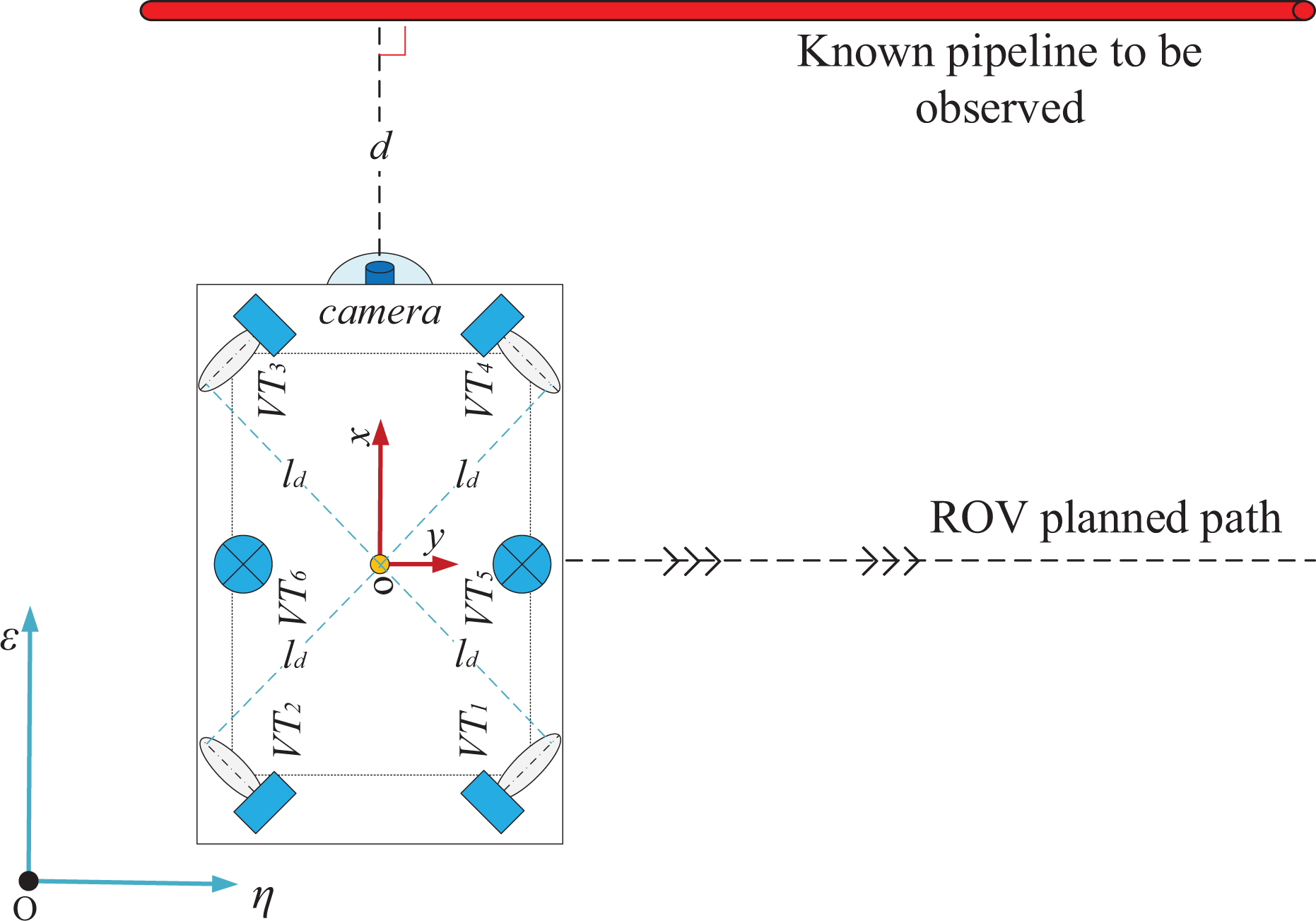
Observation task with constant heading and specified path. ROV: remotely operated underwater vehicle.
In Figure 3, it is important to obtain high-quality video of the target pipeline with stable observation angle and distance, for reducing the difficulties of image process and vision-based dimension measurement. Generally, the fluctuation of heading would lead to the fluctuation of ROV position as well, which influences the observation quality more seriously than the fluctuation of observation distance. The operation efficiency mainly depended on the transversal motion performance of the ROV. Thus, the heading control performance of the ROV needs to be ensured first, followed by the longitudinal motion performance, and lastly the transversal motion ability.
Similar measures could be taken for the rendezvous and docking task of ROV and some other tasks. ROV motion ability depends on the forces and moments generated by the propulsion system closely. Hence, how to introduce the idea of priority into the thrust allocation method is the main problem to be solved in this article. Meanwhile, how to further use the remaining unsaturated thrusters in the propulsion system to generate more desired forces and moments is also a meaningful research issue.
Multistep thrust allocation method based on priority idea
This article proposed a multistep thrust allocation method based on priority idea. The key steps of the new method include piecewise thrust allocation of single force/moment, thrust allocation of multiple forces and moment based on priority idea, and thrust redistribution among unsaturated thrusters.
Piecewise thrust allocation of single force/moment
Assume that

The matrix

According to equation (9), there is

where

where
τdx , τdy , and τ dn are calculated with amplitude limitation by the motion control module. Assume that the thrust range of each horizontal thruster is

where T max is the maximum forward thrust and T min is the maximum reverse thrust. Usually, T min is smaller than T max due to the asymmetry of the propeller. Therefore, the range of τdx , τdy , and τdn in the control module can be set as
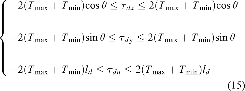
To generate a single force/moment by using equation (13), two of the four horizontal thrusters have to provide forward thrust and the other two provide reverse thrust. Moreover, the amplitude of the forward thrust is the same as that of the reverse thrust. It is obvious that the two thrusters with reverse thrust are more likely to be oversaturated, while the other two thrusters with forward thrust may not reach T max. This may result in the desired force or moment could not be satisfied by using equation (13). Thus, a piecewise thrust allocation method of single force/moment is proposed considering the asymmetry of the thrust range. We define that

In the piecewise thrust allocation method, different distribution strategies are adopted according to the desired forces and moment. We distribute each of the desired forces and moment among the four thrusters by using equation (13) as long as the desired value is within the set threshold. If the desired force or moment was beyond the set threshold, the excess portion would be distributed among the two unsaturated thrusters. The piecewise thrust allocation of each of the desired forces and moment is designed as


Thrust allocation of multiple forces and moment based on priority idea
Based on the thrust allocation of single force/moment, equation (12) can be rewritten as

Note that the result calculated by equation (20) may also exceed the thrust range of the thrusters in the propulsion system. In order to avoid oversaturation, we replace equation (20) with

where k 1, k 2, and k 3 are parameters in the value range of [0, 1]. The thrust allocation problem described in equation (21) can be solved by optimizing k 1, k 2, and k 3 with appropriate objective function and constraints.
Take the observation task for example again, we need to ensure the demand of moment with the highest priority, then to satisfy the demand of longitudinal force as much as possible, and finally to generate transversal force with remaining capacity of the propulsion system. To meet the requirement of the specified priority order, it must be true that k 3 = 1. Then, the objective function of the optimization problem can be described as to find the maximum value of k 1, and find the maximum value of k 2 on the premise that k 1 gets the maximum value. We denote the objective function as

The constraints of the optimization problem can be expressed as

There are 12 linear inequalities in equation (23). The optimization problem consisted of equation (22) and equation (23) is a linear programming problem with the solution located at one of the vertexes of the intersection area. To solve the optimization problem, we firstly obtain all the intersections of the 12 lines that correspond to the 12 inequalities. After that, all the intersections are brought into equation (23) for judgment, and we select the intersections that satisfy all the inequalities. Finally, the optimal solution that meets equation (22) can be obtained by sorting the selected intersections.
Thrust redistribution among unsaturated thrusters
Equation (21) does not guarantee all the desired forces and moment could be satisfied. We denote that

where τex , τey , and τen are the errors between the desired values and the actual values.
In practical application, all thrusters need to produce the maximum thrust is not a usual situation. Hence, it is still possible to further use the remaining unsaturated thrusters in the propulsion system to reduce the errors in equation (24). According to the configuration of the propulsion system, we divide the horizontal thrusters into six groups (VT 1, VT 2), (VT 2, VT 3), (VT 3, VT 4), (VT 1, VT 4), (VT 1, VT 3), and (VT 2, VT 4). Ideally, (VT 1, VT 2) and (VT 3, VT 4) can be used to generate longitudinal force, (VT 2, VT 3) and (VT 1, VT 4) can be used to generate transversal force, and the other two groups can be used to generate moment.
To further use the unsaturated thrusters to generate τex , the vector composed of extra thrust to be produced by the four thrusters is expected to be

where

Similarly, to eliminate the other two errors, we have


where
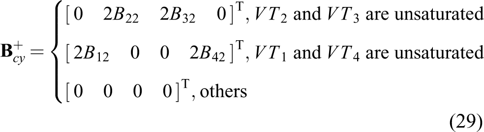
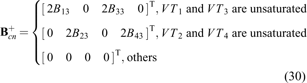
Combined with equation (21), the final solution of the thrust allocation problem is expected to be

However, the oversaturation problem has not be considered in equation (31). Therefore, a modified calculation method is used, as

where kc 1, kc 2, and kc 3 are parameters to be optimized in the value range of [0, 1]. This thrust allocation problem is similar to that in equation (21).
In the observation task, there is kc 3 = (1 − k 3) = 0. Then, based on the priority idea, the mathematical model of the parameter optimization problem can be established as

subjected to

The optimization problem could be solved by using the method in the “Thrust allocation of multiple forces and moment based on priority idea” section as well.
Implementation of the new thrust allocation method
When implementing the thrust allocation module of the ROV through programming in practical engineering, the thrust allocation result is calculated by using equation (12) according to the desired forces and moment firstly. Then, judge whether the result exceeds the thrust range of the thrusters. If not, the result would be regarded as the output of the thrust allocation module, and the allocation process is finished. Otherwise, recalculate the output of the thrust allocation module by using the new thrust allocation method. For example, in the observation task, the output based on the new thrust allocation method could be calculated with the following steps:
Simulation results
To verify the effectiveness of the new proposed thrust allocation method, two groups of simulations are carried out on a work class ROV. One group is the tests of the new thrust allocation method compared with the pseudo-inverse method, and the other is the comparative simulations of the ROV control based on the different thrust allocation methods. The size, weight, inertia, and hydrodynamic coefficients of the ROV are shown in Table 1. The configuration parameters of the propulsion system are θ = 45°, lb = 1 m, and the thrust range of each thruster is [−1400, 2000] N.
Parameters of the work class ROV.
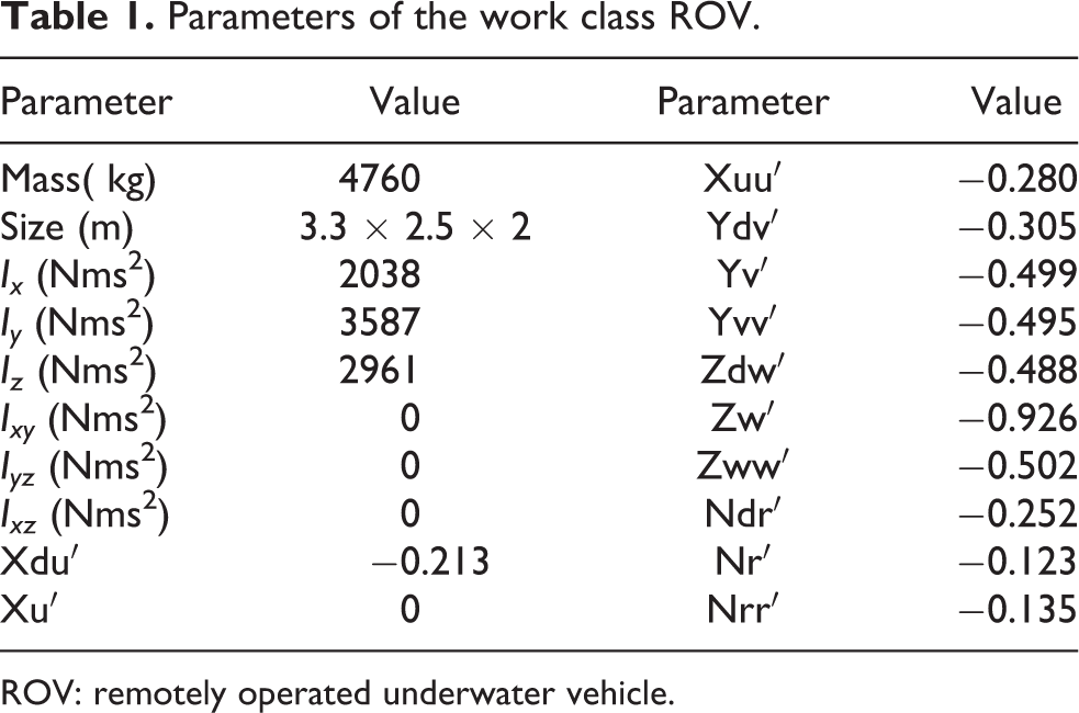
ROV: remotely operated underwater vehicle.
Simulation of the new thrust allocation method
In this simulation, three sequences of random values in the range of [−4800, 4800], [−4800, 4800], and [−6800, 6800] are generated firstly, to simulate the desired τdx , τdy , and τdn , respectively. Then, the pseudo-inverse method and the new proposed thrust allocation method are used separately to distribute the desired forces and moment among the four thrusters, and allocation results are shown in Figure 4. At last, the actual forces and moment generated by the propulsion system are obtained, and the oversaturation situations are identified, as shown in Figures 5 and 6.

Thrust commands calculated with the two thrust allocation methods.

States of the propulsion system with the two thrust allocation methods.

Actual forces and moment generated with the two thrust allocation methods: (a) full view and (b) local enlargement.
It can be found from Figures 4 and 5 that the oversaturation problem occurs frequently by using the pseudo-inverse method, whereas the problem has been completely eliminated by the new thrust allocation method. The results of the two methods appear different when there is oversaturation by using the pseudo-inverse method.
For the pseudo-inverse method, not all the desired values could be fully satisfied when oversaturation occurs, for example, the results between 24s and 29s shown in Figure 6(b). Due to the adoption of priority idea, the new thrust allocation method ensures the desired moment can always be met in any situation, though the other desired forces could not be guaranteed, as shown in Figure 6(a). However, we should note that, many times, the desired forces can still be met by using the new thrust allocation method while oversaturation occurs by using the pseudo-inverse method, for example, the results between 25s and 25.5s shown in Figure 6(b). This good phenomenon mainly benefits from the thrust redistribution method among unsaturated thrusters.
We use the integral of absolute error (IAE) as a performance index to evaluate the two methods, and the comparisons are shown in Figure 7.

Results of IAE with the two thrust allocation methods: (a) IAE of the longitudinal force, (b) IAE of the transversal force, (c) IAE of the moment, and (d) total IAE. IAE: integral of absolute error.
Figure 7 shows that the IAE of the longitudinal force with the new thrust allocation is slightly smaller than that with the pseudo-inverse method at most time, while the IAE of the transversal force is slightly larger and the IAE of the moment is far smaller. The total IAE with the new thrust allocation method is much smaller than that with the pseudo-inverse method. Figure 7 further indicates that the proposed new thrust allocation method can fully embody the expected priority idea and has a higher propulsion system utilization rate compared with the pseudo-inverse method.
Simulation of the ROV control based on the new thrust allocation method
In this simulation, the dynamic model, controller model, thrust allocation model, and thruster model of the work class ROV are built in MATLAB/Simulink. It is assumed that the deep-sea current is 0.2 kn with the direction of 45°. At the beginning of the simulation, the ROV is working in dynamic position control mode with the target horizontal position (0 m, 0 m) and heading 0°. At 500s, the ROV is switched into path tracking mode to move along the η axis with the target heading 0°. In order to obtain the maximum traverse speed, the desired τdy output by the control module is set at 4800 N, and the other desired force and moment are determined by the corresponding proportion integration differentiation (PID) regulators according to the tracking errors. The simulation results of the ROV under different load disturbances are compared with the results of the ROV based on the pseudo-inverse method.
ROV under no load disturbances
In this case, the ROV runs without load disturbances, and the simulation results based on the two thrust allocation methods are shown in Figure 8.

Simulation results of the ROV under no load disturbances: (a) north position, (b) east position, (c) heading, (d) actual longitudinal force, (e) actual transversal force, (f) actual moment, (g) desired longitudinal force, (h) desired transversal force, and (i) desired moment. ROV: remotely operated underwater vehicle.
Figure 8(a) to (c) shows that the ROV based on the two different allocation methods has the same motion control performance in the first 500s. However, the ROV based on the pseudo-inverse method fluctuates by about 0.28 m in the north direction and 5° when switched into the path tracking mode, while the ROV based on the new thrust allocation method has no fluctuation at this time. Since the motion mode has been changed, we can also find that the ROV based on the new thrust allocation method moves faster and further compared to the ROV based on the pseudo-inverse method.
The comparison results above can be well explained from Figure 8(d) to (i). In the first 500s, the desired forces and moment calculated by the control module are small, which could be satisfied by using both thrust allocation methods. Therefore, the ROV based on the two methods has exactly the same motion property at the early stage. When switched into path tracking mode at 500s, the adjust process of the ROV based on the pseudo-inverse method might be concluded as follows: Firstly, the control module suddenly generates a desired transversal force of 4800 N. Although the desired longitudinal force and moment remain unchanged at this time, the actual longitudinal force and moment of the ROV are changed from 18 N and 0 Nm to −22 N and 72 Nm due to the oversaturation problem, resulting in the variation of north position and heading. Then, the PID regulators calculate and update the desired longitudinal force and moment according to the tracking errors continuously, and the actual force and moment change synchronously. Finally, the ROV recovers to the target north position and heading after a short adjustment period. But we have to note that in order to achieve the actual longitudinal force of 18 N and moment of 0 Nm, the control module needs to output the desired longitudinal force of 450 N and moment of −650 Nm, causing only transversal force of 4370 N generated. Compared with the ROV based on the pseudo-inverse method, the ROV based on the new thrust allocation method can give priority to generate 0 Nm moment and 18 N longitudinal force when desired transversal force of 4800 N is added suddenly, which will not cause any fluctuation. Besides, the actual transversal force generated is as much as 4789 N, leading the ROV based on the new thrust allocation method to have faster transversal speed.
ROV under small load disturbances
In this case, a step moment disturbance of 600 Nm is injected at 1000s and a step longitudinal force disturbance of 800 N is injected at 2000s. The simulation results of the ROV under small load disturbances are shown in Figure 9.
Simulation results of the ROV under small load disturbances: (a) north position, (b) east position, (c) heading, (d) actual longitudinal force, (e) actual transversal force, (f) actual moment, (g) desired longitudinal force, (h) desired transversal force, and (i) desired moment. ROV: remotely operated underwater vehicle.
The main performances of the ROV under small disturbances are shown in Table 2. It can be concluded from the results that the ROV based on the new allocation method has much smaller fluctuation under both load disturbances and moves a little farther. Especially, under the longitudinal force disturbance, the ROV based on the pseudo-inverse method fluctuates by about 10°, while the ROV based on the new allocation method does not have any heading fluctuation. The main reason for the strong anti-jamming capability of the ROV based on the new thruster allocation method could also be explained.
Comparison of the two methods under small load disturbances.

ROV under large load disturbances
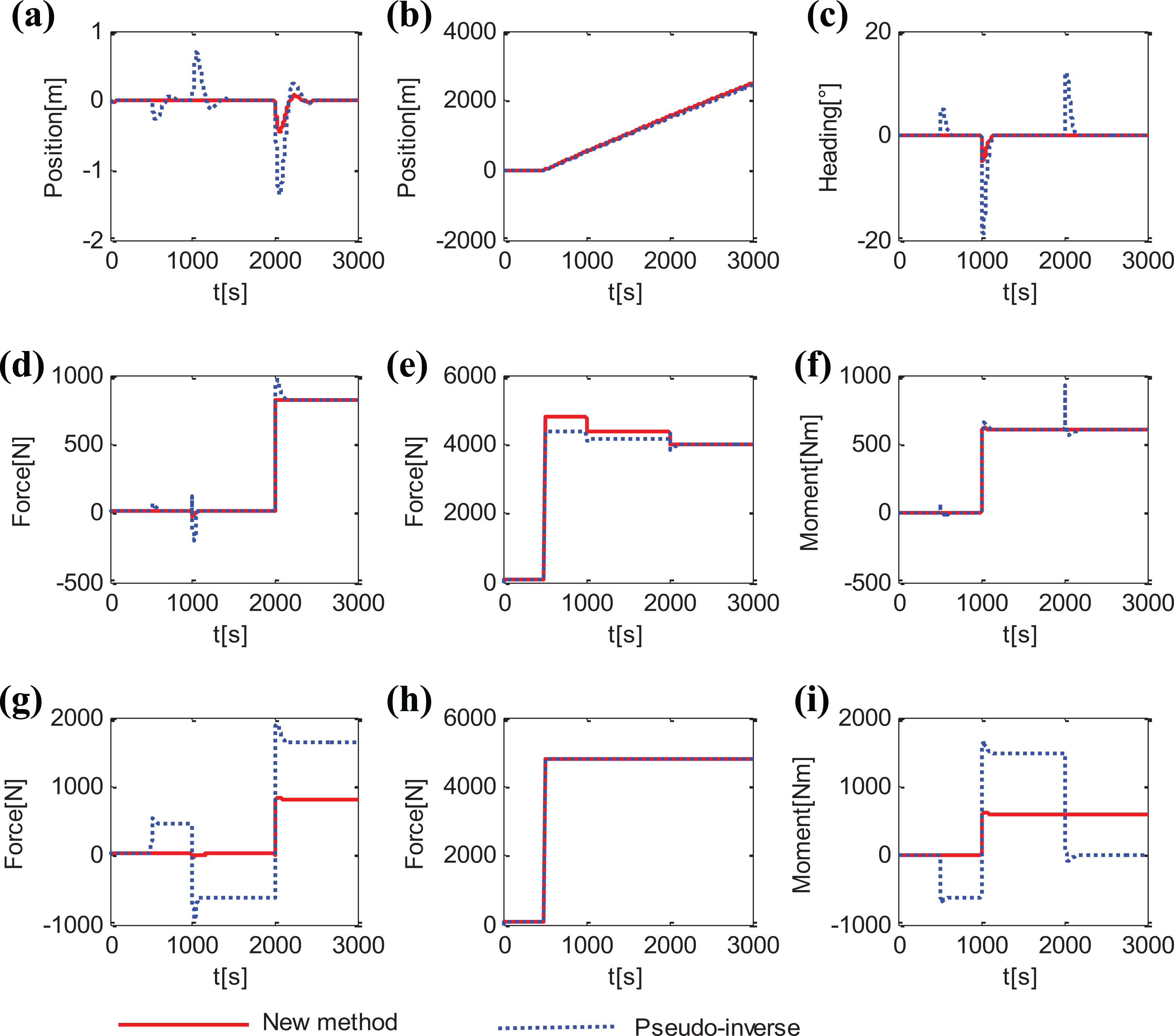
Large load disturbances, a step moment disturbance of 1600 Nm at 1000s and a step longitudinal force disturbance of 2400 N at 2000s, are injected to the ROV in this case. The simulation results are shown in Figure 10.

Simulation results of the ROV under large load disturbances: (a) north position, (b) east position, (c) heading, (d) actual longitudinal force, (e) actual transversal force, (f) actual moment, (g) desired longitudinal force, (h) desired transversal force, and (i) desired moment. ROV: remotely operated underwater vehicle.
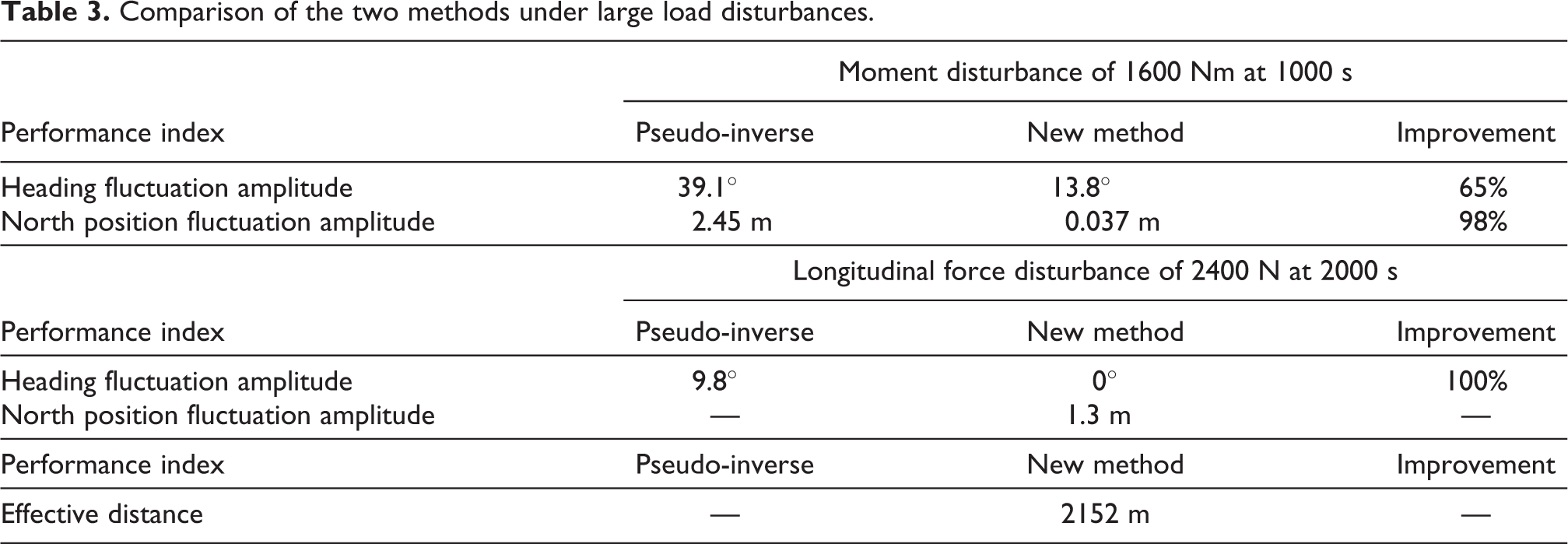
The main performances of the ROV under large disturbances are shown in Table 3. Compared with the results in the “ROV under small load disturbances” section, we can find that the fluctuations of both north position and heading increase as the moment disturbance is larger at 1000s. But the ROV based on the new thrust allocation method still has smaller fluctuation compared with that based on the pseudo-inverse method under the same moment disturbance. When longitudinal force disturbance of 2400 N is injected, although the ROV based on the pseudo-inverse method can control the heading successfully, it has lost the control ability of the position in the north direction. However, the ROV based on the new thrust allocation method has no heading fluctuation and can recover to the target north position through short adjustment, meaning it still has the ability to complete the path tracking task.
Comparison of the two methods under large load disturbances.
Conclusion
Inspired by the motion requirements of ROV for some typical operation tasks, a multistep thrust allocation method based on priority idea is proposed and verified through various comparative simulations. The main conclusions are as follows: The new thrust allocation method adopts the priority idea and thrust redistribution technology, which makes the actual forces and moment generated meet the expectation, and obtains high utilization rate of the propulsion system. The work class ROV based on the new thrust allocation method has better anti-interference characteristics, stronger adaptability, and higher operation efficiency in the given motion task under various disturbances. The proposed thrust allocation method also has the advantages of simple implementation and strong real-time performance. It has wide application prospects in other equipment with the increasingly intelligent, complex, and special operation tasks.
In future work, more priority orders (all with the same priority, two of them with the same priority, etc.) need to be considered to meet the application in engineering. In addition, priority idea-based thrust allocation method for other configurations of thrusters will be studied.
Footnotes
Declaration of conflicting interests
The author(s) declared no potential conflicts of interest with respect to the research, authorship, and/or publication of this article.
Funding
The author(s) disclosed receipt of the following financial support for the research, authorship, and/or publication of this article: This research was funded by the Major Scientific and Technological Projects of Hainan Province (No. ZDKJ2019002).