
Abstract
Applying a control system with low energy consumption and low load of motion control to robots, similar to living organisms, is considered to be one of the most important issues in robot development. We have been studying systems that use pulse-type hardware neural networks to control robotic motion with a small number of control signals, as is the case in living organisms. In particular, it has been mimicking the function of the central pattern generator localized in the spinal cord of living organisms to generate motion patterns. In the present article, a new biomimetic control system using pulse-type hardware neural networks for biped gait control is reported.
Keywords
Introduction
Computationally, expensive control algorithms for a robotic system can result in high power consumption, ultimately leading to the inability to operate the system continuously. Reducing the control load and power consumption is considered to be one of the most important issues in developing robots.
However, humans and animals can reduce the control load by distributing the functions of intelligence and motion with the central nervous system. In addition, the central nervous system operates with very low energy consumption for both intelligence and motion control. Mimicking the control system of a living organism, which has a system that controls locomotion with a lower control load and lower power consumption, has the potential to be applied to robots.
Focusing on motor control in humans and animals, a central pattern generator (CPG), which is localized in the spinal cord, creates patterns for movement to reduce the control load. 1 The CPG generates control signals to induce basic locomotion, that is, walking or running. The CPG is considered to have a two-layered structure: rhythm generation (RG) that generates basic rhythms and pattern formation (PF) that forms muscle activity patterns. 2 This suggests that the rhythm of the gait and the muscle activity of the legs are independently controlled. When the PF of the muscle is activated, it has a muscle synergy structure that coordinates the muscles required for the motion. 3
Focusing on human gait locomotion, Ivanenko et al. showed that human gait locomotion can be reconstructed with only five signals, based on an analysis of muscle activity during walking. 4 They also showed that the walking and running can be switched between simply by changing the position of the second signal. 5 In addition, Aoi et al. and Ivanenko et al. mathematically analyzed a CPG model that induces muscle synergy and simulated walking and running using the musculoskeletal model. 6
Artificial neural networks, such as the CPG, have been studied. Moreover, studies have also examined hardware neural networks, 7 –9 which mimic biological neural networks by means of electronic circuits. Since circuit constants are incorporated into the network, parameter adjustment is difficult. However, such a network can be processed at high speed, even for complex or large-scale networks. In addition, such networks can operate with low power consumption because they handle electrical signals directly. We focused on the pulse-type hardware neural networks (P-HNNs) 10 proposed by Sekine et al., which can generate bio-like pulsed signals. P-HNNs can generate a variety of pulse patterns, making it easy to reproduce biological motion patterns.
Previously, we studied the motion control and implementation of robots using the CPG model with P-HNNs. We developed a CPG model that can change its gait pattern and controlled the gait of a quadruped robot. 11 The gait locomotion of a microrobot with link legs of less than 5 mm in length was realized by controlling the CPG model fabricated by an Integrated circuit (IC). 12 The CPG model for biped gait control was proposed using P-HNNs, and the switching between the walking and running patterns was investigated as muscle synergy signals. From the output simulation of the walking and running patterns, the walking and running locomotion of the biped model were geometrically simulated. 13 In addition, the IC chip for biped gait control was designed and the walking and running control by the output of the IC chip was shown. 14 However, the control of the walking and running motions of a musculoskeletal robot using the output of the proposed CPG model for biped gait control has not been investigated.
In the present article, a method of biped gait control for the musculoskeletal robot using the CPG model with P-HNNs was investigated. Using the inputs of the walking and running patterns of the previously proposed CPG model for biped gait control as the timing of muscle contraction, the walking and running locomotion of the musculoskeletal model were geometrically simulated. From simulations of walking and running locomotion in the musculoskeletal model, muscle groups that contract in coordination were classified. Based on the proposed CPG model and the results of muscle coordination analysis of the musculoskeletal model, we report on the consideration of biped gait control for a musculoskeletal robot with low power consumption and low motor load.
CPG model for biped gait control using P-HNNs
Based on physiological and anatomical findings, the CPG model was proposed to generate five temporally continuous myoelectric potential patterns that activate the muscles required for walking and running. 5 In the present study, the CPG model that outputs the five spatiotemporal patterns for walking and running was constructed using an electronic circuit to control the gait locomotion of the robot. Figure 1 shows an overview of the output of the CPG model. The voltage output is used to operate the actuators of the robot according to the five spatiotemporal patterns.

Overview of the output of the CPG model. (a) Walking pattern and (b) running pattern. CPG: central pattern generator.
In order to switch between walking and running patterns, a circuit that resembles an input from a higher center was incorporated into the CPG model. Although the CPG can generate rhythmic movements without input from the higher centers, the possibility of adjusting the gait speed based on the input intensity of the higher center and sensory information was suggested. 15 Figure 2 shows an overview of the CPG model that switches between the walking and running patterns depending on external inputs.

Overview of the proposed CPG model. CPG: central pattern generator.
Components of the CPG model
Cell body model and synaptic model
The cell body model generates pulses periodically, just like a biological neuron. The cell body model consists of N-type and P-type MOSFETs, resistors RG , RL , R 1, and R 2, capacitors CG and CM , and supply voltage VA . The cell body model can be switched between the self-excited oscillating mode and the separately excited oscillation mode by adjusting the supply voltage. By varying the supply voltage VA and the capacitors CG and CM , the pulse width and period can be varied as desired. Figure 3 shows a circuit diagram of the cell body model.

Cell body model.
Neurons in living organisms transmit pulses through synapses. The transmitter released by the synapse changes the membrane potential of the receiving neuron. Synapses that raise the membrane potential are called excitatory synapses. Synapses that lower the membrane potential are called inhibitory synapses.
The synaptic model mimics the function of excitatory and inhibitory synaptic models. The output of the cell body model through the excitatory synaptic model oscillates by in-phase synchronization. The output of the cell body model through the inhibitory synaptic model oscillates in anti-phase synchronization. Figure 4(a) shows the excitatory synaptic model, and Figure 4(b) shows the inhibitory synaptic model.

Synaptic model. (a) Excitatory synaptic model and (b) inhibitory synaptic model.

Diagram of the CPG model. CPG: central pattern generator.
CPG model
The developed CPG model generated patterns with 6 spatiotemporal pulses from the mutual inhibitory connections of 6 cell body models and 30 inhibitory synaptic models. Since the five consecutive spatiotemporal patterns of the CPG model correspond to the leg postures of walking and running, respectively, the output order must be fixed. Therefore, the trigger circuit shown in Figure 6(a) was connected to the six-cell body, models and trigger pulses were input. Each cell body model that receives trigger pulses in the order of C1 to C6 is suppressed from firing by mutually inhibitory connections. Since the cell body model requires a charge to the capacitor before it fires, the capacitor is charged and fires in the order in which the trigger pulses are input. Therefore, once the trigger pulse is input, the output of the CPG model is fixed.

Diagram of (a) the trigger generation circuit and (b) the switching circuit.
To switch between the second pulse in the walking and running patterns, the C2 and C3 pulses were input through the excitatory synaptic model to the C2′ and C3′ cell body models in separately excited oscillation mode. This allows us to take the output of C2 and C3 without affecting the output of the six cell body models that are mutually inhibited and connected.
As mentioned above, it has been suggested that CPG regulates gait speed by input from higher centers as well as sensory information. Therefore, the switching circuit that pseudo-reproduces the external input was incorporated into the CPG model. Figure 6(b) shows the switching circuit. The switching circuit was connected to C2′ and C3′. The switching circuit is connected to the GND when the switch is ON and drops the output of the cell body model to the GND. In other words, the C2′ switch can be turned on in order to generate the walking pattern, and the C3′ switch can be turned on in order to generate the running pattern.
Simulation of the CPG model
Two cell body models, self-excited oscillating mode and separately excited oscillation mode, were used. The circuit constants for the self-excited oscillating mode were RG
= 560 kΩ, RL
= 10 kΩ, R
1 = 15 kΩ, R
2 = 20 kΩ, CG
= 0.22
Two types of synaptic models were used: excitatory and inhibitory. The circuit constants for the excitatory synaptic model were
The circuit constants of the cell body model and the synaptic model described above were adjusted by changing the circuit constants in the circuit simulation. The pulse pattern of the CPG model is determined by the pulse period and pulse width of the cell body model. The main oscillating element of the cell body model is the charging and discharging of the capacitor. Therefore, the pulse period and width can be adjusted by adjusting CG and CM .
Figures 7 and 8 show the output results of the walking and running patterns. In Figure 7, out of the six pulses, the switching circuit connected to C2′ turned on and the output of C2′ dropped to GND, confirming the generation of the walking pattern. In Figure 8, out of the six pulses, the switching circuit connected to C3′ turned on, and the output of C3′ dropped to GND, confirming the generation of the running pattern. The gait cycle of the walking pattern and the running pattern were both approximately 1.0s because the circuit constants used were the same. Five spatiotemporal patterns of walking and running were reproduced, as revealed by the analysis of muscle activity. In addition, the timing of the second pulse of the running pattern was found to be changing.
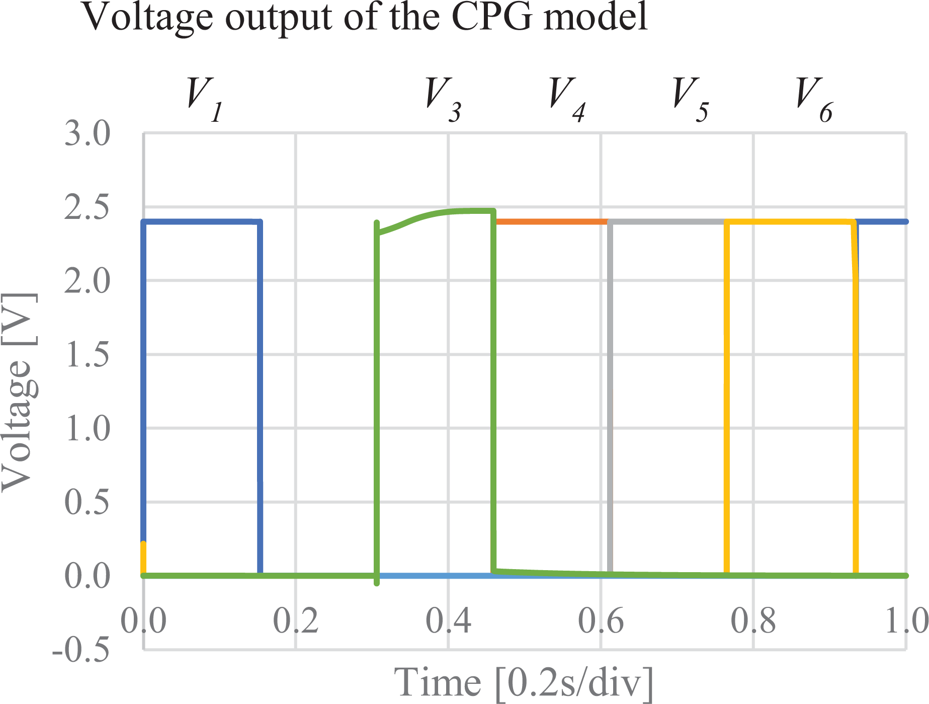
Output of the walking pattern.

Output of the running pattern.
Muscle coordination analysis by the musculoskeletal model
Components of the musculoskeletal model
Physiological findings indicate that 25 muscles are involved in gait locomotion. The musculoskeletal model used in this experiment was a lower body model, focusing on leg movements of the lower limbs. The model has 18 muscles on one side and 36 muscles in total. The musculoskeletal model was fixed in the sagittal plane in order to focus on the gait locomotion. In addition, one gait cycle is defined as two steps of one leg in gait analysis. 16 Therefore, the initial state of the musculoskeletal model was set as the right leg in front of the body.
Figure 9 shows the constructed musculoskeletal model. Table 1 shows the abbreviations used for 18 muscles. In Figure 9, the area shown in red is the muscle. A linear actuator was placed on the muscle, and only the muscle displacement in each posture during walking and running was handled. Therefore, no dynamic action or characteristics as an actuator are applied. As a preliminary step in the dynamic simulation, the fabricated musculoskeletal model was used to classify the muscles that contract in coordination according to the walking and running patterns of the CPG model. Therefore, the skeleton and muscles are assumed to be rigid bodies with no physical properties applied.

Musculoskeletal model.
Abbreviations of 18 muscles.

Muscle coordination by gait motion simulation
The walking and running motions were referenced from existing human walking and running joint angle data. The extracted joint angles were divided by the cycles of the walking and running patterns generated by the CPG model. By inputting segmented joint angles to the musculoskeletal model in advance, the timing of muscle contraction was reproduced by inputting the walking and running patterns, and the transition of coordinated muscle groups was shown. In this case, the right leg was focused on classifying the muscle groups that contract in a coordinated manner. Figure 11 shows the joint angles input to each joint of the right leg. The joint angles were set for one gait cycle.
When each of the five patterns of pulses was input, the muscle groups were classified in coordinated groups by focusing on contracting muscles. The fact that muscles in principle only operate in a one-dimensional direction was considered. Figure 10 shows the walking and running simulations.

Walking and running simulation. (a) Simulation of the walking locomotion and (b) simulation of the running locomotion.
Tables 2 and 3 show the coordinated muscle groups during walking and running, respectively. The muscles commonly used for walking and running were confirmed. These are indicated by cells shaded with a dotted pattern in Tables 2 and 3. We considered the muscles indicated by dots to be agonist muscles that act primarily during walking and running. In this case, the input timing of signals 1, 3, 4, and 5 of the CPG models is the same for both walking and running. The above results are in close agreement with those shown in the analysis of muscle activity during walking and running in physiological findings, where the muscles operated during walking and running by four signals other than the second signal are mostly common. 6
Coordination group of muscles in walking.a

a  represents muscles commonly used for walking and running,
  represents muscles stretched while walking and running, and
  represents muscle with little or no extension or contraction.
Coordination group of muscles in running.a

a represents muscles commonly used for walking and running, represents muscles stretched while walking and running, and represents muscle with little or no extension or contraction.
On the other hand, the muscles that were changed to stretch were confirmed. These muscles are indicated by cells shaded with a vertical striped pattern in Tables 2 and 3. We considered these muscles to be antagonistic, that is, acting in opposition to the agonist. The muscles with little or no change in displacement were also confirmed. These muscles are indicated by cells shaded with a diagonal striped pattern in Tables 2 and 3.
To control the walking and running of a musculoskeletal robot from an engineering point of view, it is considered possible to switch between walking and running by inputting the five spatiotemporal patterns of the previously proposed CPG model 13 to the corresponding muscle actuators. To operate the muscles commonly used for walking and running, the locomotion is generated by inputting signals 1, 3, 4, and 5, which have the same input timing. The main difference between the walking and running is that the input timing of the second signal changes. Therefore, when generating the walking, the second signal with a later timing should be input to the muscle group in the third line of Table 2. When generating running, the second signal with an early timing should be input to the muscle group in the second line of Table 3. Therefore, it is considered to be possible to control the walking and running of musculoskeletal robots by means of periodic spatiotemporal patterns.
Discussion
Evaluation of the musculoskeletal model
The musculoskeletal model was made to walk geometrically without adding any physical characteristics. Then, muscle groups that contracted in coordination were classified. However, it is important to consider the physical properties and to conduct dynamics simulations close to the actual environment in order to develop the actual robots. In particular, the elastic element of the muscle has a significant influence on the gait locomotion of the musculoskeletal model and its control by P-HNNs.
Biological muscles have been suggested to have characteristics that stabilize body joints during movement due to their elastic properties. 17 In addition, it is considered that humans perform gait locomotion passively due to the physical interaction between body structure and gravity. 18 By mimicking the anatomical structure in addition to the elastic properties of the muscle, the musculoskeletal model is thought to assist in various forms of locomotion, including gait. By adding the physical properties and anatomical structure of the muscle to the musculoskeletal model, the model is expected to generate stable walking motion. The pulse pattern in the proposed CPG model is the input that causes the muscle to contract. In order to use the elastic properties of the muscle to control the assistance of movement with the CPG model, it would be necessary to consider a circuit configuration that can change the strength of the pulse input to the muscle.
The joint angles input to the musculoskeletal model were based on the measured human joint angles available on OpenSim. 19 Therefore, the gait motion was almost the same motion. Compared to the simulation motion, the period of time when the angle was fixed at a certain level without the input of the CPG model was confirmed. In Figure 11, the period was approximately 0.2s to 0.3s.

Joint angles of the right leg.
When simulating under gravity, it is expected that the gait locomotion will be assisted by the muscles due to the physical interaction and muscle properties as described above. The musculoskeletal model, upon input of the walking pattern, steps forward with the leg. The model then moves to fall forward, which is considered to be a human-like walking motion. By replacing the period during which the hip angle is fixed with the period during which it falls forward, gait locomotion is considered to be possible in the dynamic simulation.
However, the amount of muscle contraction in the musculoskeletal model would need to be adjusted. Therefore, we will proceed with the experiment to reproduce the gait locomotion by inputting the amount of contraction of the muscle groups shown in this experiment into the musculoskeletal model.
In the present study, the musculoskeletal model was fixed in the sagittal plane, and the focus was on the muscle groups that contract in coordination, prompting leg movements in gait locomotion. Therefore, the musculoskeletal model focuses on leg movements and simplifies the human walking motion. However, in gait analysis and pathology, it has been suggested that human gait locomotion is not only leg movement, but also pelvic movement is an important factor. 16,20 In order to study bipedal gait control by musculoskeletal robots, it is important to simulate the motion in 3D space considering the motion of the pelvis.
Evaluation of the control system
Based on the results of the muscle coordination analysis, biped gait control of the musculoskeletal robot is considered to be possible by inputting the timing of the proposed CPG model 13 to the muscles common to walking and running. In addition, it is considered possible to control the switching between walking and running of the musculoskeletal robot by varying the input timing of the second signal. In gait locomotion, the leg movement needs to change in accordance with the order in which the CPG outputs. The order in which the legs move can be adjusted using the trigger circuit of the CPG model. It was considered that the gait locomotion of the musculoskeletal robot could be controlled by fixing the output order of the CPG model with the trigger circuit and inputting each signal to the corresponding muscle. The walking and running require changing the position of the second signal among the five signals. The switching circuit of the CPG model could be used to change the timing. By switching the switching circuit, walking and running can be controlled by outputting a signal with a slower timing for walking and a signal with an earlier timing for running.
The intelligence and locomotion of conventional robots are controlled by the CPU. However, it is inferred from the power consumption, which will be high because the CPU performs all processes. Focusing on motion control, it is likely that further power will be required from the use of actuators and sensors.
The HRP-4 20 developed by Kawada Industries, Inc. uses Intel Pentium M 1.6 [GHz] as the control CPU. The rated power consumption of the Intel Pentium M 1.6 [GHz] is listed as 24.5 W. 21,22 However, it is inferred that controlling intelligence and motion as described above will result in a power consumption of approximately tens to hundreds of watts higher than rated.
The purpose of the proposed hardware CPG model is to control locomotion as in living organisms. The main feature of this system is that the system controls a musculoskeletal robot like a biological body and operates with low power consumption using analog electronic circuits. In the simulation, the power consumption of the proposed CPG model was approximately 9.5 mW. The proposed CPG model is shown to operate with lower power consumption, as compared to the CPUs mentioned above. The proposed CPG model is assumed to use the same actuators and sensors as the CPU-controlled robot. It is assumed that the same actuators and sensors as those used in the CPU-controlled robot can be used for motion control with low power consumption.
Based on these results, a method for coordinated control of multiple muscles indicated by physiological findings was proposed by the CPG model for biped gait control using P-HNNs. It was shown that a small number of control signals from the CPG model could reduce the load of motion control of the robot. It was confirmed that the proposed CPG model can generate nonlinear pulse patterns with low power consumption by using electronic circuits. Therefore, it is possible to develop a system that can control complex motions, such as those of living organisms with low power consumption.
Conclusion
In the present article, a method for bipedal gait control of a musculoskeletal robot using the CPG model with P-HNNs was investigated. The walking and running motions of the musculoskeletal model were geometrically simulated using the input of the walking and running patterns of a previously proposed CPG model for biped gait control for the muscle contraction timing. From these simulated walking and running motions, muscle groups that contracted in coordination were classified. From the results of the muscle coordination analysis of the proposed CPG model and the musculoskeletal model, we discussed the bipedal gait control of the musculoskeletal robot with low power consumption and low motor load.
Footnotes
Declaration of conflicting interests
The author(s) declared no potential conflicts of interest with respect to the research, authorship, and/or publication of this article.
Funding
The author(s) disclosed receipt of the following financial support for the research, authorship, and/or publication of this article: The present research was supported by the Nihon University Robotic Society (NUROS) and by a Nihon University Multidisciplinary Research Grant for 2020.