
Abstract
In this article, direct numerical simulations of flow around NACA0012 hydrofoil with superhydrophobic surface (SHS) is presented. Surface heterogeneity takes into account by periodic no-slip and shear-free grates on the surface. The study is conducted for a range of
Introduction
Hydrofoil as a basic structural unit is frequently applied in ship and marine engineering to supply sufficient lift force or maneuvering control ability for ship and underwater structures as well as energy harvesting equipment, and so on.1–6 The essential requirement of hydrofoil is to provide a wide range of lift force with a relative low drag resistance cost. Many attempts are devoted to improve and study the influence of such hydrodynamic characteristics.5–9
High aspect ratio micro/nano-topography combined with low surface energy results in super water-repellent surfaces. So far, various techniques are proposed to control the flow pattern passively. Among these drag reduction technologies, surfaces based on Lotus leaf effect10,11 are one of the most promising techniques for this purpose. These surfaces are known as superhydrophobic surfaces (SHS). Decrease in surface energy manifest the repulsion of water molecules over superhydrophobic surfaces which leads to maintain fluid contact with smaller part of the surface. Due to contact with only a part of such surface, both the chemical bonding and reaction between the surface and fluid are reduced. Reduction in the drag force not only improves the velocity of airplanes and ships but also plays a vital role to save energy by minimizing the fuel consumption.
Barthlott and Neinhuis 10 in 1997 conducted a detailed microscopic study of the lotus leaf is as a pioneering work on superhydrophobic surfaces. Superhydrophobicity of a surface is described by Cassie-Baxter (fakir-state) model. 12 In fakir-state, liquid sits on the ridges of surface and air is trapped in between these roughness structures. Thus, form a heterogeneous interface of liquid-gas and liquid-solid.
Artificial superhydrophobic surfaces can be manufactured by chemical coating along with roughening (riblets and ridges on surface) of material. Such rough structures provide slip characteristic over surface area. Navier was the first to propose a relation for slip as

where
Notable decrease in drag force and increase in lift force is evident for a number of hydrofoils. However, low efficiency of superhydrophobic airfoils are recorded at larger angles of attack. Low efficiency of airfoils is associated with growth of separation bubble. 21 Slip velocity as large as 50% of free-stream’s velocity can be obtain over SHS. From two-dimensional numerical simulations, delay the critical Reynolds number to an extent and the onset of vortex shedding is found in presence of slip boundary condition.22,23
Non-wetting slip surfaces are started to use vigorously to control the flows around blunt bodies and delay of vortex shedding in wake along with drag reduction. The dramatic change in the wake behind NACA 0012 is observed experimentally with the increase in angle of attack at Re = 2000−10,000. 24
Patterned microgrooves have great importance in the area of microfluidic devices. Flow around circular cylinders with pattern grooves at low Re from 100 to 1000 is investigated. 25 As a result, decrease in shedding frequency, delay in separation, reduction in friction-drag, and lift are noted due to slip.25,26 About 10% drag reduction and 40% reduction in the recirculation bubble in wake was obtained in experimental study conducted by Kim et al.27,28 at Re = 0.7–2.3 × 10⁴.
Alternation in flow pattern on a Joukovsky hydrofoil (maximum thickness to chord length ratio is 0.25) is analyzed. The experiment was carried out in a water tunnel and particle image velocimetry technique was used for investigation. Highest drag reduction 18% was observed at Re = 1500 and drop in drag reduction is noted with increase in Re. 17 However, only zero angle of attack is considered in their study, and few studies are available which investigate the effect of superhydrophobic surfaces combined with angle of attack.
In the light of previous investigations, primary objective of this study is to provide the useful information about flow behavior over 3D NACA0012 airfoil at Reynolds number 1000, with the particular focus on the influence of superhydrophobic surface. Thus, it is meaningful to study the influence of SHS on flow around streamline body at low and moderate Reynolds number and to identify the effect on three dimensional instabilities as NACA hydrofoils are most prevalent shapes in applied marine systems. The selection of present Reynolds number 1000 is served as a represent, since the most of sea animals swim in the range of Re from 0.01 to 109. Superhydrophobic surfaces are inspired by bionic surfaces in water which helps to sea animals to swim with low friction. Furthermore, there are plenty of studies on the experimental and numerical study at such Re for comparison.
One may expect that flow behavior with closed Reynolds number is similar but with variant critical angles of attack. Additionally, 4-digit symmetric NACA series possess good stall characteristics together with angle of attack, speed, and other conditions. In this study, NACA0012 is chosen to analyze the effect of superhydrophobic surface on marine vehicles. We expect, in future these surfaces can be applied to ship industry which will be helpful to save energy resources. In this work, periodic slip and no-slip boundary condition is used to model the superhydrophobicity.29–31
This article is organized as follows: Section “Methodology” presents the geometry and methodology used. Section “Results and discussion” illustrated the instantaneous and mean behavior of aerodynamic forces along with the three dimensional wake flow. In the last Section “Concluding remarks,” a brief conclusion is given.
Methodology
Mathematical model
A symmetric hydrofoil NACA0012 of sharp trailing edge is used for computational purpose. Incompressible Navier-Stokes equation is as follows,


where

where b is the pitch length and w is air interface.31,32 Schematic diagram of computational domain, hydrofoil with superhydrophobic boundary conditions are depicted in Figure 1. C-grid topology is used around hydrofoil.
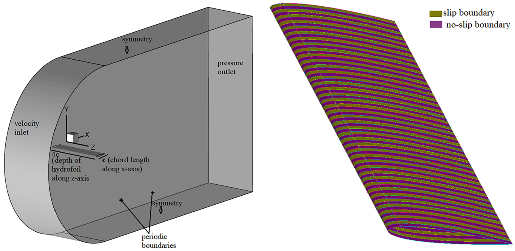
Schematic 3D model of computational domain (left). Periodic shear-free and slip boundary conditions over surface of NACA0012 (right).
Mesh independence and methodology verification
Spanwise wavelength is considered as 4c so that spanwise flow structures could be fully observed, where c is chord length of hydrofoil.
Navier-Stokes equations are solved by using commercial software Ansys Fluent v19.1. Second order implicit discretization is utilized to discretize space and temporal domains. Simulations are carried out at
Mesh independence study
A 2D mesh is constructed at first and hydrofoil surface is discretized with 320 nodes. Height of first layer of mesh is kept at 0.0002c next to the hydrofoil surface. Total of 0.198 million quadrilateral cells are used for two-dimensional mesh. For benchmark, present results of mean coefficients of drag
Comparison between literature and present study data (a) coefficient of drag and (b) lift coefficient for 2D geometry.

Three-dimensional mesh is constructed by extruding 2D geometry and domain in z-direction, resulting in identical mesh of same resolution in all the planes normal to the spanwise direction. Schematic 3D model of computational domain and boundary conditions are shown in Figure 1.
Convergence of hydrodynamic force
In context to adopt shear-free and slip boundary conditions over hydrofoil surface, convergence of hydrodynamic forces is analyzed by keeping G.F = 0.5 at angle of attack
Coarser grid points for G.F = 0.5.

Finer grid points for G.F = 0.5.

For fixed grid points, mean values of
Results and discussion
Hydrodynamic forces
Comparative results for mean drag and lift coefficients for 2D versus 3D hydrofoil with G.F = 0, and 3D hydrofoil with no-slip and shear-free surface are presented in Figures 2 and 3. Additionally, the time history comparison of Cd and Cl for different gas-fractions are presented in Figures 4 and 5. Influence of superhydrophobic surface on the hydrodynamic forces is clear from figures. In case of lower angles of attack, hydrodynamic forces are symmetric. Difference is more obvious for higher and lower gas-fractions. At higher angles of attack (20° and 25°) random distribution of lift and drag force is observed.
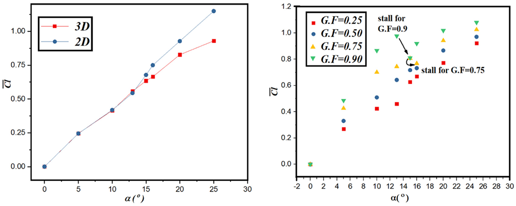
Comparative results for mean drag coefficients for various angle of attack at G.F = 0, (right) 2D versus 3D flow and (left) G.F ≠ 0.

Comparative results for mean lift coefficients for various angle of attack at G.F = 0, (right) 2D versus 3D flow and (left) G.F ≠ 0.

Comparative time history of coefficient of lift force at various gas-fractions for different angles of attack:(a) 10°, (b) 15°, (c) 20°, and (d) 25°.

Comparative time history of coefficient of drag force at various gas-fractions for different angles of attack:(a) 10°, (b) 15°, (c) 20°, and (d) 25°.
Drag reduction measurement entirely depends on the gas-fraction. For superhydrophobic surface, at angle of attack zero-degree drag reduction is perceived while there is no lift. The increase in drag and lift forces is reported for increasing angle of attack. However, rate of decrease in growing drag reduction is noticed for higher gas-fractions. DR rate of 19% for gas-fraction 0.5 (compared to smooth surface hydrofoil (G.F = 0)) at
Lift force increases rapidly until
Delay in flow separation is reported by Murlidharan in case of grooves normal to the flow direction. Early separation occurs when micro grooves are aligned to the direction of flow.
22
From time history plot of Cd (Figure 5(c) and (d)), the low drag reduction is explicit. As a result, lift force becomes lower. Consequently, stall is observed for
Manipulated difference in the absolute values of lift and drag forces (

Variation in
The same procedure is applied to manipulate
Wake behavior
Instabilities in the wake of bluff bodies to incoming flow are most classical problem of fluid dynamics. Superhydrophobicity is well known for the delay of the separation bubble and the intensity of vortex shedding frequency to a large extent in flow over circular cylinders.32,38,39 In current numerical study, phenomenon of delay is clearly observed. In case of SHSs, flow field strongly depends on the surface heterogeneity as compared to angle of attack. Additionally, it is found that superhydrophobic surfaces are able to modify critical Reynolds number and turbulence as well.22,24 Comparative wake flow for various angles of attack and cavity sizes demonstrates the effect of superhydrophobicity on flow field (Figure 7).
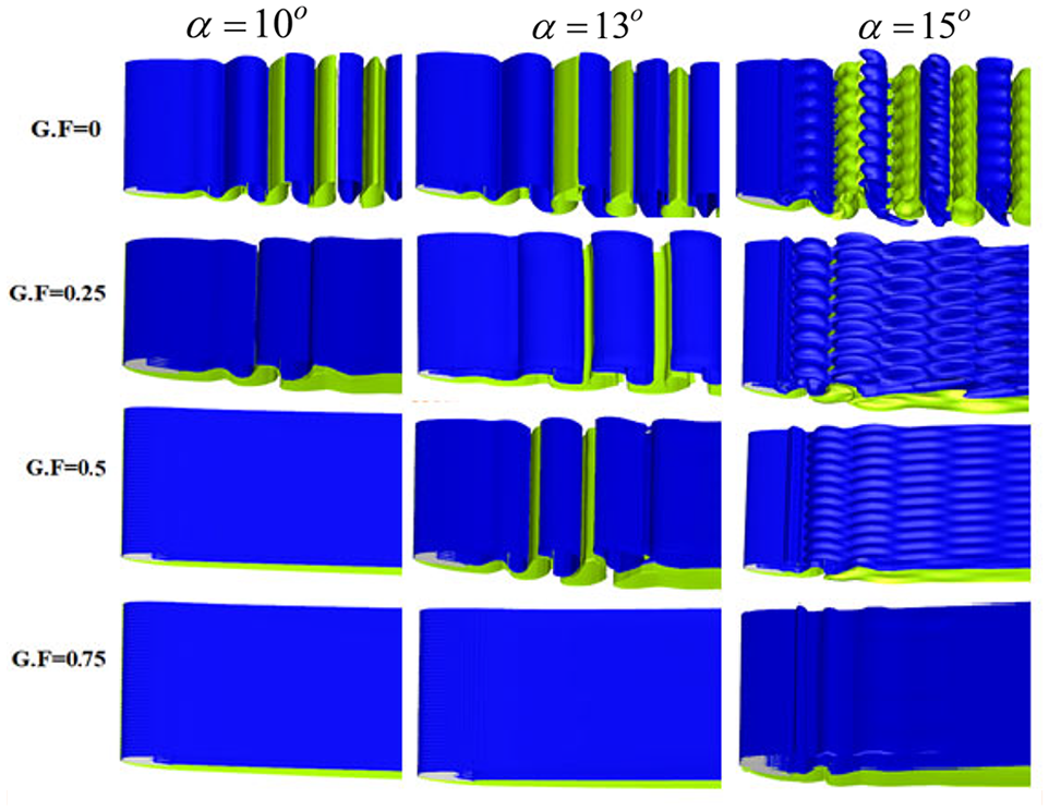
Comparative results of iso-surfaces of
In the case of no-slip surface hydrofoil, flow remains laminar and a separation bubble grows near trailing edge for lower angles of attack. At angle of attack 10°, flow becomes fully developed two-dimensional. Furthermore, on increment in angle of attack, wake alters to three dimensional state. Typical wake structures are calculated by iso-surfaces of
In presence of heterogeneous surface, flow modification is obvious (Figure 7). In case of low angles of attack, at lower gas-fractions, vortices are shed in wake with weak strength, showing wake behavior similar to flow over hydrofoil surface with no-slip condition for initial gas-fractions. As gas fraction increases, wake flow becomes steady and laminar. At α = 10°, transition from 2D flow to steady laminar occurs at G.F = 0.5, whereas, at α = 13°, transition takes place at G.F = 0.75 (Figure 7). Thus, critical Reynolds number of transition for wake delays up to higher Re. Thus, superhydrophobic surfaces increase the length of the recirculation region in the wake, which results in the delay of the onset of vortex shedding.
For higher angle of attack 15°, weakly three-dimensional wake is observed with growing gas-fraction. For G.F = 0.9, vortex street diminishes and wake becomes laminar attached to the trailing edge of the hydrofoil for lower as well as higher angles of attack. It is interesting to note that the heterogeneous surface has modified the wake behavior so that both three-dimensional and two-dimensional wake are observed at same angle of attack but for different gas-fractions. Thus, alters the critical angle of attack to higher angles of attack with respect to gas-fraction for Re = 1000.
The explanation to flow behavior over SHSs provided in literature. 21 As surface heterogeneity traps the air layer and thickens the boundary layer on the surface. Due to meniscus liquid-solid contact area becomes lower and decrease velocity gradient. As a result, increase in wall slip and decrease in shear stress is observed as a result shedding frequency decreases which mimics the vorticity and wake becomes two-dimensional steady laminar. In present study, surface heterogeneity considered by shear-free boundary condition provides the slip to fluid similar to the case by trapping air between micro/nano-ridges. Thus, phenomenon of delay in separation is clearly observed.
On further analysis of angle of attack 15°, Mode C wake characteristic is observed at

The iso-surface of Mode C at angle of attack 15°. Blue and green color indicates the positive and negative values. Gray color shows the surface of hydrofoil.
Uniformly distributed parallel braid like Mode C structures along spanwise direction of the hydrofoil are observed. Mode C was firstly observed by Zhang both experimentally and numerically. Mode C are commonly observed in the bluff bodies wakes of time 2T-periodic.33,40,41 Shedding frequency and subharmonic frequencies are shown in Figure 9 for 15°. f1 represents the main shedding frequency. While, the other subharmonic frequencies are also observed (Figure 9).

Fast Fourier transform analysis for angle of attack 15° (a) G.F = 0, (b) G.F = 0.25, (c) G.F = 0.50, where the wake flow is three-dimensional and Mode C is observed.
With further increment in angle of attack (20° and 25°), flow becomes complicated as all vorticity components becomes dominant in flow. Top view of instantaneous three-dimensional wake pattern is given in Figures 10 and 11. Blue and red color represents the positive and negative components of
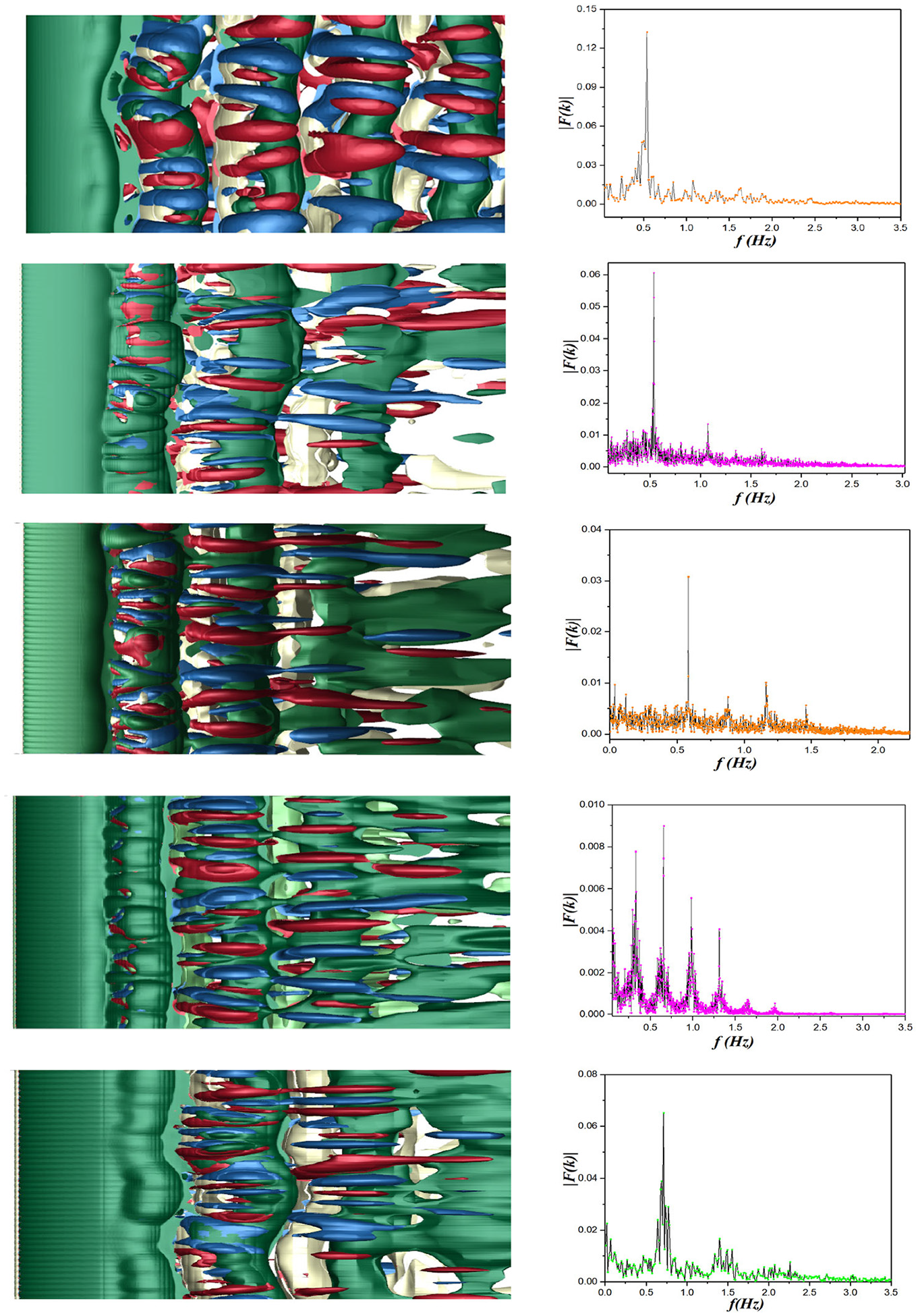
Wake flow for gas-fraction 0–0.9 at angle of attack 20° along with FFT analysis.

Wake flow for gas-fraction 0–0.9 at angle of attack 25° along with FFT analysis.
Three-dimensional vortex structures are calculated for ±0.5. Frequency spectrum is calculated by streamwise velocity component. Frequency analysis shows that for higher angles of attack, there is no constant shedding frequency in spanwise direction. Frequency distribution becomes more complicated due to smaller vortices present in wake flow. The oscillations are swept by the fast-moving fluid in case of chaotic flow, which results in low Strouhal numbers.
For a fixed angle of attack, pre-dominant frequency increases with the increase in gas-fraction. Whereas, being consistent with other flow variables trend is reverses with increase in angle of attack (frequency decreases). Overall, SHSs do not cause the significant impact on wake structures at higher angles of attack. Thus, the superhydrophobic surface its functionality and not effective enough to affect the chaotic flow. This type of observation is also reported in experimental study of superhydrophobic surface. 24 Growth in drag reduction is also found to become lower at higher angles of attack.
Strouhal number is calculated for each gas-fraction corresponding to angles of attack. Strouhal number versus gas-fraction for a range of angles of incidence is plotted in Figure 12, and it is found to decrease with the increase in angles of attack for a fixed gas-fraction.

Strouhal number versus gas-fraction for angle of attack 10°–25°.
Mean velocity, slip length, and shear stress measurements
Texture of superhydrophobic surface traps air to form plastron and reduce frictional force (present between solid surface and liquid) experienced by fluid while flowing. Additionally, plastron allows a fluid to flow over a surface with an effective slip. Figures 13 and 14 demonstrate the velocity over heterogeneous surface of hydrofoil and the effective slip length respectively. Effective slip length is calculated by the mean velocity over the surface of hydrofoil constructed through alternating slip and no-slip surfaces. Then it is obtained based on the definition of the slip length represented in equation (1).

Normalized velocity over the surface of NACA0012 with SHS for different angles of attack.

Corresponding relationship between
Amount of slip is quantified through slip length. From Figure 14, it is evident that normalized effective slip length depends on G.F which is also observed from existed literature for turbulent and fully developed laminar flows. 42 From numerical results, it is clear that increase in gas-fraction causes higher slip length. Furthermore, the velocity over the surface of hydrofoil with the increase in gas-fraction becomes higher.
Slip length is usually regarded as hydrophobic performance with angle of attack. However, it is not necessary that in presence of angle of attack, slip length follow the same rule (increase in angle of attack does not imply increase in slip length). Gas-fraction can hamper the slippage and thus reduce the slip length for varying angles of attack. Therefore, decrease in slip length as well as mean velocity over superhydrophobic surface is observed for higher angles of attack (Figures 13 and 14).
Wall shear stress is computed in various studies over superhydrophobic surfaces to determine the slip length and drag reduction. About 10% drag reduction was reported fabricated hydrofoil surface. Shear stress (

Results for normalized shear stress for varying G.F.
Concluding remarks
In this paper, direct numerical simulations for the flows over a NACA0012 hydrofoil with superhydrophobic surface are performed. Superhydrophobic surface is modeled by applying shear-free and no-slip boundary conditions over the surface of hydrofoil. Numerical results demonstrate the superhydrophobic surface implementation as a promising drag reduction technology. Flow field modifications are found to be dependent on both the angles of attack and gas-fractions at fixed Reynolds number 1000. As shear-free region provides the slip characteristic, a number of interesting results are found such as
Appreciable DR and lift enhancement are obtained. With increment in gas-fraction lift and drag reduction increases in general. Drag reduction grows monotonously with the growth of gas-fraction on SHS.
Early stall is observed on SHS as compared to smooth surface hydrofoil.
Normalized shear stress decays for higher gas-fraction. As a result, mean slip velocity over the surface intensifies. Corresponding variation in velocity profile are observed when compared to the hydrofoil with smooth surface of same computational domain.
Vortices are weakly shed in wake for lower gas-fractions and wake behaves almost similar as for no-slip surface. Furthermore, wake remains two-dimensional form for lower gas-fraction and lower angles of attack (10° and 13°). As angle of attack increases, wake flow alters to three-dimensional structure. However, at higher gas-fractions, superhydrophobic surface delays the separation bubble and reduce the instability of wake. Therefore, no disturbance in the wake is found even at higher angle of attack, and flow remains two-dimensional.
Three-dimensional as well as two-dimensional wake structures are observed at angle of attack 15° for varying gas-fraction.
Mode C appears at higher angles of attack for lower gas-fractions.
In presence of superhydrophobic surface, the critical Reynolds number for the transition of the wake flow from two to three dimensions alters.
Microscopic pattern of the surface directly affects the boundary layer and lead to macroscopic flow modification.
Aforementioned numerical results give useful insights to the superhydrophobic surface technology. Although, the number of grates are limited in this study due to computational resource and cost. However, this could be worthwhile in practical applications of engineering in commercial scale.
Footnotes
Acknowledgements
The authors thank SCTS/CGCL HPCC of HUST for providing computing resources.
Handling Editor: Chenhui Liang
Declaration of conflicting interests
The author(s) declared no potential conflicts of interest with respect to the research, authorship, and/or publication of this article.
Funding
The author(s) disclosed receipt of the following financial support for the research, authorship, and/or publication of this article: The author YL Xiong acknowledges the grant of the National Natural Science Foundation of China (NSFC, Grant Nos. 11872187 and 12072125). author D Yang would like to thank the financial support from the National Natural Science Foundation of China (NSFC, Grant No. 51779097).