
Abstract
With the wide application of redundant manipulators, sharing a working space with humans and dealing with uncertainty seems an inevitable problem, especially in the dynamic and unstructured domain. How to deal with obstacle avoidance is of particular importance that robots and humans/environments are safe interactions to fulfill the complex cooperating tasks. This paper aimed at solving the problem of multiple points avoidance for the reaction motion based on the skeleton algorithm in unstructured and dynamic environments. A method named “sensor-based skeleton modeling and MVEEs approach of the redundant manipulator for the reaction motion” is proposed. The extraction of skeleton information from image is obtained to calculate the distances of the multiple control points and establish the repulsion in this method. Afterward, the force Jacobian related to the priority weighting factors is calculated and then a reaction force with damping term is established, which is corresponding nominal torque commands. For the redundant manipulator, the joint angles are obtained through torque iteration instead of inverse kinematics to reduce calculation cost. Finally, the method was tested by a 7-DOF manipulator in the ROS framework. The obtained results indicate that the method in this method can realize dynamic obstacle avoidance and time cost reduction.
Keywords
Introduction
Collaborative robots are finding many applications in fields such as manufacturing, health care, agricultural production, and social tasks. Compared to tightly structured environments, cooperation-type robots are made to interact closely with humans in collaborative contexts in an unknown and dynamic environment while robots have to detect and avoid obstacles. In this case, it is necessary for performing real-time reactive strategies to deal with all possible collisions instead of precisely following a predefined path. Some related researches include fixed control points, 1 multiple-point control, 2 modification of reaction paths. 3
For high-dimensional configuration space (C-space) formed by the high degree of freedom (high-DOF) robots, the problem of planning a feasible path in a dynamic environment is one of the most complex and time-consuming tasks in the field of robotics and it can cause easily a dimension explosion. Probabilistic and randomized approaches, such that Rapidly-Exploring Random Tree (RRT), 4 Probabilistic Roadmap Method (PRM), 5 have been used to resolve this problem of the dimensionality. 6 When the changes in the environment are inevitable, the potential fields are commonly used to estimate the reactive motion intent of the robots modeled as particles. 7 In particular, it has obvious advantages in dynamic obstacle avoidance 8 and dynamic target tracking, 9 however, these focused primarily on the mobile robots. When it comes to a redundant manipulator which is consists of a multiple-link structure with a certain volume and cannot be represented by a particle, the problem becomes challenging because there exist some intrinsic constraints such as local minima issues and fluctuations transferred to narrow passages. 10 Many attempts have been performed to develop various ways to handle these limitations.11–15 Whereas these main studies are the target for collision avoidance at the end-effector of the manipulator from the perspective of kinematics. For the redundant manipulator composed of multiple-link, the collision of arbitrary points may occur in the process of planning, but it is seldom discussed.
For collision avoidance, it needs to regard the motion of the robot at the arbitrary point as a possible reactive movement, and the problem has been extensively described in the robotics literature. The complete framework and its implementation have been elaborated in Brock and Khatib, 3 although the major effort remains on the computation of control points position and corresponding Jacobian matrix. Alejo et al. 16 put forward a real-time reactive collision avoidance method for multiple aircraft which has been applied in industrial environments. From the control viewpoint, a more general reactive motion approach called the “replanning and deformation methods” has been described. 17 While approaching an obstacle, the planner first attempts to apply deformation and the robot can continue to replan if only the path remains feasible. In Cui et al., 18 combining a reactive path-planned approach with the Dubins curves and the artificial potential field (APF) method solves the path planning of the robot in a dynamic environment.
For reactive collision avoidance in human-robot interaction (HRI), it is necessary to track the key parts of the objects while a control system can take corrective actions before collisions. One major way for the introduction in unstructured environments depends on sensors to compute the distances between possibly colliding parts. In this context, the reliability and stability of the sensor directly correlate with the safe interaction with robot and human/environment. The Point Cloud Library (PCL)19–21 is the most common approach for obstacles or environments modeling with the visual sensors. However, the main shortcoming is that this method cannot fully describe the obstacle information in the environment. In Wu et al., 22 a high-dimensional grid model was used to model the known static obstacles, and the potential field method was adopted to process the unmodeled dynamic obstacles for the manipulator trajectory planning. Flacco Fabrizio 23 proposed a method based on depth space offline mapping to divide depth space into depth grids. These two methods require that the main camera must cover the entire robot workspace, which has low computing efficiency and requires parallel computing to accelerate. As a common characteristic, the idea of directly calculating the distance of the environment image was introduced in Kuhn and Henrich. 24 To improve performance in the computational time cost, the authors25,26 proposed a new method to assess the distances between a general point in Cartesian space and an object perceived by the depth sensor, but it can only be applied to a single sensor. In Li et al. 27 presents an environment modeling method for the manipulator using the offline mapping between the depth image and OctoMap in a dynamic non-structured environment. However, when the distance evaluation is calculated, only the real-time obstacle avoidance research of the end-effector is regarded.
In this paper, a method of sensor-based skeleton modeling and multiple virtual end-effectors (MVEEs) approach of the redundant manipulator for the reaction motion is proposed. In this framework, the geometry and architecture of the manipulator and objects are obtained by the extraction of the skeleton based on the three-dimensional (3D) sensor. Then the possible multiple collision points and distances can be calculated based on the skeleton model. Finally, the priority weighting factors are defined according to the virtual repulsive force and the reaction force is generated, resulting in corresponding nominal torque commands. Compared to the previous research, the primary contributions are listed as follows: (1) A method to get the skeleton online based on 3D vision sensor is proposed. (2) The bounding box was constructed and the distance calculation of the manipulator’s multiple control points and obstacles based on the real-time detection of skeleton model, which dramatically reduces the computational complexity. (3) For the redundant manipulator composed of multiple links, the MVEEs approach based on the skeleton model is realized to avoid the dynamic obstacle and the joint angles are obtained through torque iteration instead of inverse kinematics to reduce calculation cost.
Vision-based skeleton and bounding box modeling
A policy that automatically selects the control points in the whole process of motion, based on sensor information, could make it efficient for the application of human-robot interaction. It is important to note, however, that these control points should be able to be calculated quickly and result in simple distance computation. In this section, the skeleton algorithm and the bounding box modeling for dynamic objects for fast multiple-point control, are described.
Depth space model of the object
Figure 1 shows four coordinate systems that exist in the process of obtaining image information by the 3D sensor. The origin of the camera frame, which is described by the world frame, is defined as the optical center. The image pixel frame is on the top-left side of the image, (u, v) are the columns and rows of the pixel, respectively. The focal length f is the distance between the imaging plane’s center and the camera optical center.

Coordinate relation of the 3D vision sensor.
The vision sensor is modeled as a typical pinhole camera which is constituted of two main parts: the intrinsic parameters matrix K denoted the projection of a Cartesian point on the image plane, and the extrinsic parameters matrix ε represented the coordinate transformation between the world and the sensor frame. Considering each point has the pixels given by the RGB camera and the distance in the depth space which is expressed as Pd = (u, v, dp)T, the Cartesian point Pc = (xc, yc, zc)T in the sensor frame is given by:

Where
Thus, we can calculate point P = (xW, yW, zW)T in the world frame as follows:
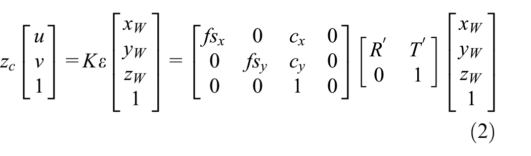
Where
Building the skeleton
In this section, the skeleton extraction is based on the idea of thinning, that is, remove some points from the original image, but keep the original shape, until the skeleton of the image is obtained. All the definitions are followed by the Zhang-Suen method. 28 Supposed a 3 × 3 window is applied and each element of the pixel (i, j) is related to its eight neighboring elements as shown in Figure 2.

Representation in a 3 × 3 window.
As well known that a pixel value at the nth iteration rests on the new pixel and its eight adjacent pixels at the (n − 1)th iteration in image processing. The variables A(p1) and B(p1) are the 0–1 patterns numbers and nonzero neighbors numbers of p1, respectively. To preserve the skeleton pixels in the 8-connectivity sense, the two sub-iterations are described as follows.
In the first sub-step, remove the pixel p1 from the digital pattern if conditions (a)–(d) are all satisfied: (a)
In the second sub-step, the last two of the four conditions are: (c′)

Skeleton extraction.
Constructing bounding box used the geometric primitive
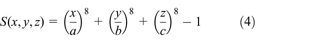
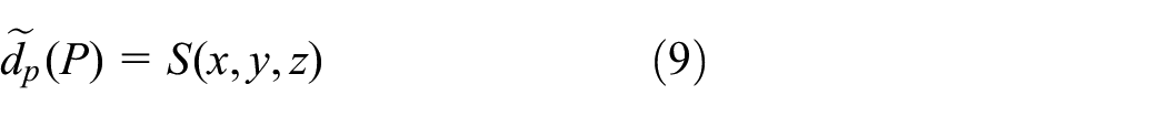
The characteristic of the objects in the workspace can be described as simple geometric primitives using the shapes of the general objects, such as cuboid, cylindrical, conical, etc. As shown in Figure 4, {ObXbYbZb} denotes the world coordinate system, and the arbitrary point P relative to {ObXbYbZb} are represented by (x, y, z). When the satellite component assembly is the main application scenario, the main types of geometric primitives using super-quadric surface functions depiction can be defined in 3D space 29 and the expression to depict a single geometry primitive is represented as follows.
(a) For a cylindrical surface, the super-quadric surface function is represented by:

(b) For a cuboid surface

Geometric primitives description of the objects.
Based on the established skeleton, the parameters such as a, b, c can be obtained by:

Then the center of the bounding box can be calculated by:

We define dimension vector

Combined with the above analysis, the eight vertex coordinates of the bounding box can be easily obtained on the basis of the established skeleton (see Figure 5(a)). In general, the Cartesian position of each joint, computed by the D-H table described in Table 2, can constitute the endpoints of the skeleton segments.

Bounding box model: (a) bounding box based on the skeleton, (b) a segment of the bounding box, and (c) the acquisition of the radius r.
Aim at safety collision avoidance, a cylindrical bounding box with the skeleton as a central axis, to which add two hemispherical bounding boxes, was constructed for the manipulator. Figure 5(b) shows a segment of the bounding box, which line AB represents the central axis of the skeleton, and r is the bounding box radius. It can be obtained that points A and B are the intersections or endpoints of the skeleton, and the radius r can be directly approximated in the SolidWorks model or calculated by the projection method (see Figure 5(c)). In view of the method for the bounding box construction based on the skeleton, it greatly provides convenience for the calculation of distance in the next section.
The corresponding distance calculation of the multiple control points
Distance calculation for a control point
Based on the description in the previous section, the control endpoints of the skeleton segments can be obtained. For any point P (x, y, z), we can judge whether it is on the obstacle surface according to the calculation of equations (3) and (4).

As shown in Figure 6, this paper takes the case of a cuboid object as the research description. The value
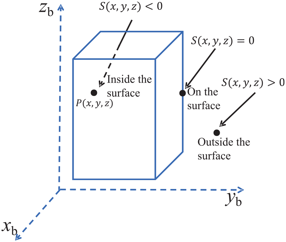
The location description between any point P and the bounding box.
Distance calculation for skeleton segments
As well known that a segment is the most likely to collide at the minimum distance, which should also be considered as a moving control point on the basis of endpoints of segments. If all the points on the segment which is denoted as link S1S2 as an example are regarded, The calculation of the real minimum value is generally very complex. In this paper, we can first judge whether the control endpoints S1, S2 are external according to equation (8). The distances of the control points S1, S2, as shown in Figure 7(b), can be approximately calculated according to equation (9), which is represented by

Schematic diagram of human-robot interaction: (a) the segment S1S2 spans the two planes, (b) the distances of the control points S1, S2, and (c) the minimum distance between the two segments.
Let


Where


and {t1, t2} is scalar values, with
When the distance is minimal, the points on the two segments are denoted the collision points pac and pbc, respectively. Thus, the common normal line can be calculated as:

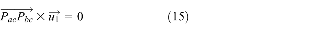

When
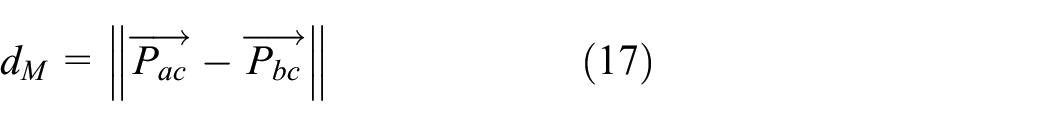
Thus, the minimum distance of a segment is obtained as:

The distances of all segments can be calculated based on the equation (18), thus the minimum distance between the robot and the obstacle can be descried by :

When there is no collision at the minimum distance, the manipulator can safely achieve collision avoidance. In the next section, details on MVEEs approach are given.
The MVEEs approach of the redundant manipulator for reactive motion
Figure 8 shows the system flow chart of collision avoidance. After constructing the bounding box based on the skeleton algorithm to calculate the distance of the multiple control points in real-time, the multiple points of each segment are equivalent to MVEEs. Then the priority weighting factors are defined according to the virtual repulsive force value and the force Jacobian matrix is obtained. Next, the velocity mapping of the joint angle to the minimum distance control point is realized by Jacobian and the reaction force, combined with repulsive force and reverse resistance (damping term) induced by velocity under the regulation of the parameter
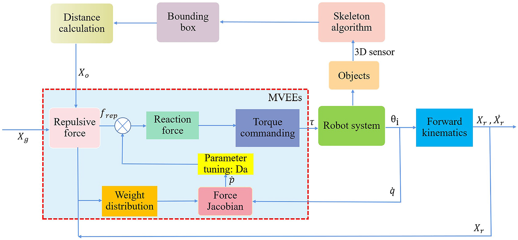
System flow chart of collision avoidance.
Generating reaction force in MVEEs
Given the framework of Figure 8, the reaction force to avoid collision consists of two parts: the repulsive force and the reverse resistance. To compute the repulsive field intensity, we calculate the distance between the multiple points of the robot skeleton and the object from the 3D sensor. The principle of constructing a repulsion field is: the robot and the obstacle are mutually repulsive and do not touch each other; meanwhile the repulsive force should gradually decrease as soon as the robot is away from the object. The safety index (defined as

Where
Figure 9 shows the repulsive force consisted of radial force

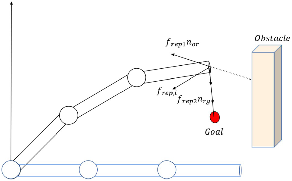
Repulsive force.
Where the unit normal vector

In fact, the tangential repulsive force from obstacle

The control point

Where
Where

It can be seen that the next is on the solution of
Definition of force Jacobian matrix based on priority weighting factors in MVEEs
As shown in Figure 10, the presence of the virtual repulsive force makes the robot offset, and the greater the force, the greater the offset of the corresponding control point. Thus, we can get the displacement change by the proportion of the force generated on each control point, that is, the priority value of each point is defined as follows:

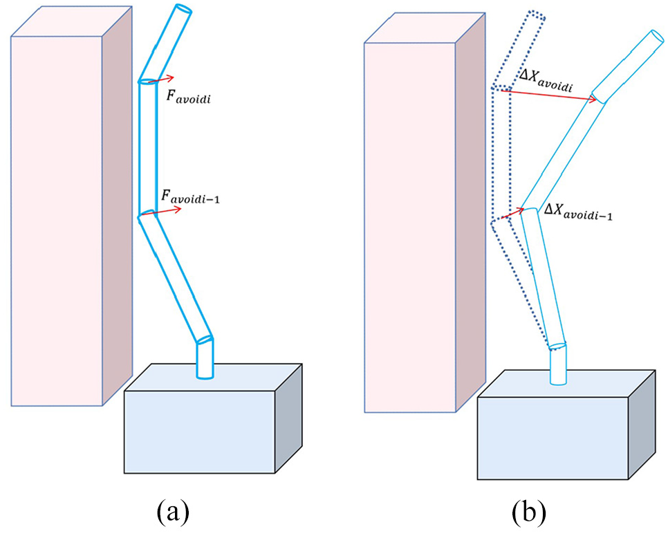
Generation of collision avoidance motion: (a) generated repulsive force at control point and (b) displacement of the control point.
Where n represents the control point numbers and l is the displacement directions caused by corresponding points.

Where
Using the decided

Where

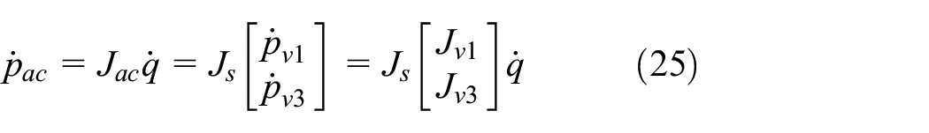
Since the manipulator is redundant, the corresponding joint-angular vectors associated with the VEE position vector based on the differential kinematics mapping can be described as follows:

Based on the above analysis, the velocity mapping relationship between the control points of each section can be obtained. Thus, the velocity-related terms can be mapped to compute the force value of equation (24), which provides a basis for the torque calculation in the next section.
Computing avoidance torques
As introduced, it is necessary to convert the desired trajectories to joint velocities or torques and the related torque is tracked in system dynamics. The avoidance torques generated by the reaction forces via the transpose of the Jacobian matrix defined in equation (25) are given:

Hence, we compute joint angles through incremental iteration of the torque. Here we use a batch update rule:

Where
Iterative updating of the joint angle.

When the end-effector is close enough to the goal if
Simulation and results analysis
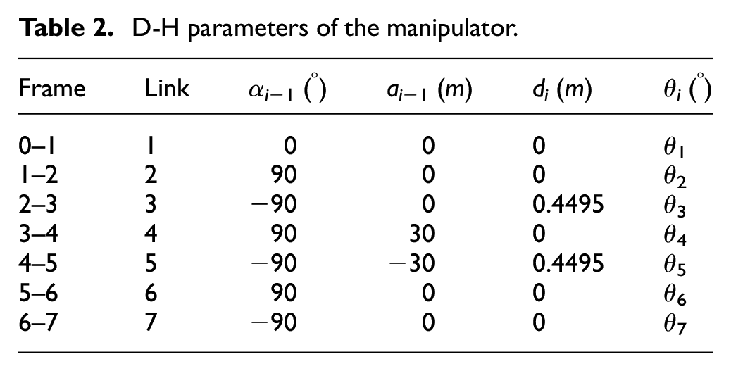
To verify the effectiveness of the proposed method in this paper, the 7-DOF manipulator is applied in the scenario of satellite component assembly via Gazebo and ROS software. As shown in Figure 11(a), human-robot collaboration in the shared narrow space to complete the work of satellite component assembly meanwhile the collision is needed to avoid. Figure 11(b) shows the simulation environment implemented through the ROS framework for this task. The detailed D-H parameters of the manipulator are presented in Table 2.

Simulation validation scenario: (a) Satellite component assembly scene and (b) simulation structure used ROS and Gazebo.
D-H parameters of the manipulator.
The simulation procedure is described as follows: When a human (obstacle) is shared with the robot in the workspace, the Kinect sensor is used for the 3D image acquisition and the skeleton is extracted according to section “Vision-based skeleton and bounding box modeling” in this paper. The bounding box can be obtained combined with the skeleton and the geometric primitive. When the manipulator is moving, we can calculate the distance information between each segment of the skeleton and the obstacle bounding box in real-time, then the movements are displayed in the Gazebo virtual environment. We set the coordinates of the target point to be (0, −0.65, 0.45) m. The initial position of the robot is in the vertical state and the starting position of the end-effector is (0, 0, 0.899) m. The safety index
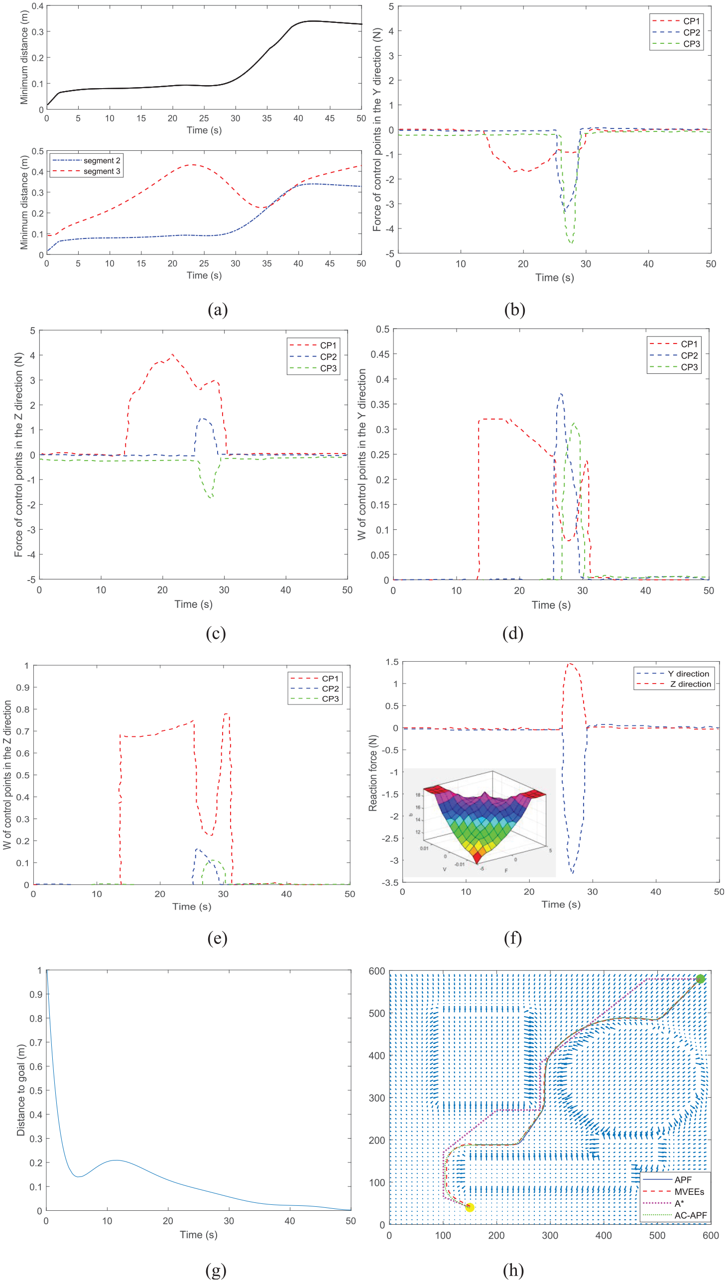
Simulation results of 7-DOF redundant robot: (a) Minimum distance of segments, (b) force of control points in the Y direction, (c) force of control points in the Z direction, (d) priority weighting factor W of control points in the Y direction,(e) priority weighting factor W of control points in the Z direction, (f) reaction force in the Y and Z direction, (g) distance to goal, and (h) comparison test of some obstacle avoidance methods.
Figure 12(a) shows the distance between the robot and the human from the starting point to the goal. The lower graph represents the minimum distance between each segment of the robot and the obstacle (human). Since the robot pedestal is fixed (see Figure 11(b)), only the elbow segment (segment 2) and wrist segment (segment 3) may collide during movement. Under this circumstance, the minimum distance of the manipulator can be obtained in the upper graph of Figure 12(a).
The repulsive forces by human versus time correspond to the control points CP1, CP2, CP3 in the Y and Z direction are drawn in Figure 12(b) and (c). It can be seen that the maximum repulsive force of the control point CP2 occurs at approximately 28 s and the distance is also the minimum (Figure 12(a)). Thus, a higher force was required for the control point being in danger of collisions to realize the avoidance.
As shown in Figure 12(d) and (e), the priority weighting factors
As shown in Figure 12(f), there are two graphs. The inset graph represents the corresponding parameter
Figure 12(g) shows the distance from the end-effector of the robot to the target point. It could be shown that the manipulator kept getting close to the goal in the first 10 s. The dynamic obstacle appeared after that time and considering the influence of reaction force, the distance from the target fluctuated. After 30 s, the reaction force is 0, indicating that the manipulator has been far away from the obstacle, so it follows the original path. It can be seen that the distance approaches zero and the manipulator reaches the goal as the gradual movement to the target point.
Discussion
As it can be seen in the simulation results section, the MVEEs approach can achieve obstacle avoidance for a manipulator with higher degrees of freedom. In view of the time cost and the superiority considerations, the graph-based basic method A*, the classical method artificial potential field (APF) for multi-DOF manipulator, and the optimization-based approach ant colony APF (AC_APF) are selected to be compared with the method MVEEs in this paper. Figure 12(h) shows the comparison tests of these methods in C-space. The results of the contrast are shown in Table 3. Two points, green and yellow, indicated the initial and goal points, while the objects, surrounded by blue, represent obstacles. The coordinates of the starting points and target points are respectively (580, 580), (160, 40).
Results for the method comparison.

Some important remarks about the feasible methods are given: the probabilistic-based method A* is applicable for manipulators to search a reachable path in a static environment. The time (245.8535 s) for the simulation process is greatly increased while the distance is almost 0.82 cm which is closer to the target point. However, it has many inflection points which lead to more vulnerability to the robot’s stopping and starting frequently, meanwhile it increases the probability of collision with the edge of obstacles that means a poor real-time performance. Moreover, it uses a pre-calculation process to identify collisions with obstacles. It means that this disadvantage grows exponentially with the complexity and size of the environment and results in the computing time and storage capacity increasing significantly.
The collision-avoidance path for manipulator using APF shows the effective simulation results in a dynamic environment and avoids obstacles in real-time. It only takes 7.4804 s in the APF method and the distance between the end-effector is approximately 148.7 cm. However, the multi-DOF manipulator is trapped in local minima, especially in a narrow passage, due to the attraction to the desired goal configuration and the repulsion to the configuration space obstacles almost equal. Aim to this problem, some optimization-based approaches are applicable to APF. The AC_APF algorithm to improve the planning of manipulator end-effector is adopted for obstacle avoidance planning. The computing time (121.6748 s) decreased by half when compared to method A* and the distance is almost 0.81 cm.
In our work, the collision-avoidance method MVEEs for the manipulator has been carried out using deterministic methodologies, and therefore the defects of probabilistic methods can be avoided. It can be seen that two methods, which take respectively 121.6748 and 245.8535 s, are at the expense of computing time compared to our method which takes 52.4186 s.
To authors’ knowledge, there is no document in the literature supporting the method MVEEs to plan multiple control points collision-avoidance trajectory for the manipulator. Meanwhile, there are fewer parameters to be adjusted only the damping term parameter
The limitation of the proposed method and future research should be focused on the following aspects:
The method of obstacle bounding box modeling based on the geometric primitive is a convex polygon in this paper, more work on concave polygon and complex obstacles in this respect should be considered.
When the multi-control point obstacle avoidance, facing multi-dynamic obstacles sharing a narrow space with the robot, is inevitable, the compliant contact control of some parts is also a worthy exploring problem.
Extending the proposed method to modeling and simulation of nonlinear systems with greater degrees of freedom robot.
Conclusion
In summary, a method of MVEEs control based on a skeleton model with the 3D-sensor is proposed to solve the problem of multiple control points avoidance for the reaction motion. The proposed approach is used to get the multiple possible collision points and distances between the manipulator and obstacles in the unstructured dynamic environment. Then, it greatly reduces the time and calculation cost through the Jacobian matrix related to the priority weighting factors. Meanwhile, a new form of a reaction force, which is corresponding nominal torque commands, to realize the joint angles iteration instead of inverse kinematics. The simulation results mean that this method can be successfully applied for the manipulator’s obstacle avoidance from beginning to end. Consequently, the MVEEs proposed in this paper could be widely applied in the field of human-robot interactions and provide a way to implement the non-contact compliant obstacle avoidance. However, it is noted that the multi-control point obstacle avoidance, facing multi-dynamic obstacles sharing a narrow space with the robot, sometimes is inevitable. In the future, based on the MVEEs, the contact compliant control of some parts deserve consideration. Also, further practical experiments will be needed to verify the simulation effect in the next step.
Footnotes
Handling Editor: Chenhui Liang
Declaration of conflicting interests
The author(s) declared no potential conflicts of interest with respect to the research, authorship, and/or publication of this article.
Funding
The author(s) disclosed receipt of the following financial support for the research, authorship, and/or publication of this article: This work was financially supported by the National Key Research and Development Program of China under Grant No. 2018YFB1305300, the National Natural Science Foundation of China under Grant No. 61763030, and the Science and technology project of Education Department of Jiangxi Province under Grant No. GJJ212501.