
Abstract
A suspension system is one of the integral parts of a hyperloop capsule train, which is used to isolate the car-body from bogie vibration to provide a safer and comfortable service. A semi-active suspension system is one of the best candidates for its advantageous features. The performance of a semi-active suspension system relies greatly on the control strategy applied. In this article, Skyhook (SH) and mixed Skyhook-Acceleration Driven Damper (SH-ADD) controlling algorithms are adopted for a nonlinear quarter-car model of a capsule with semi-active magnetorheological damper. The nonlinear vertical dynamic response and performance of the proposed control algorithms are evaluated under MATLAB Simulink environment and hardware-in-loop-system (HILS) environment. The SH controlled semi-active suspension system performance is found to be better at the first resonance frequency and worse at the second resonance frequency than the passive MR damper, but the mixed SH-ADD controlled semi-active suspension system performs better than the passive at all frequency domains. Taking the root-mean-square (RMS) value of sprung mass vertical displacement as an evaluation criterion, the response is reduced by 58.49% with mixed SH-ADD controller and by 54.49% with the SH controller compared to the passive MR damper suspension.
Keywords
Introduction
Nowadays, many companies across the world are doing researches intensively on a hyperloop capsule to unveil it as the fifth mode of transportation, and there is a high computation between them for the new achievement. A joint team from Tesla and SpaceX released an Alpha study of hypersonic speed ground transportation system concept, which is called hyperloop, in August 2013. 1 According to the proposed concept, the pods or capsules of a hyperloop move through an almost-evacuated and sealed tube system to eliminate aerodynamic resistance or friction, 2 and maximize the energy consumption efficiency. Fortunately, a new mode of transportation system was intended to be built between San Francisco, California, and Los Angeles, California corridor, that optimizes the benefits of the existing transportation system and improves the limitations. However, the proposed California High-speed Rail does not reduce current trip time and cost relative to the existing mode of transport. Therefore, the team proposed the alpha study hyperloop as the fifth mode of a transportation system for this corridor. Based on the alpha study, the hyperloop system can reduce the tripe time between Los Angeles and San Francisco to 35 min, which was 1 h and 15 min by air and 2 h and 38 min by California High-Speed Rail. 1 After the release of this alpha study as an open-source many companies and research institutes became interested to take the idea and further develop it. Nowadays, this system of transportation is under intensive research in many countries.
A hyperloop capsule is a combination of many complex integral subsystems, and one of these subsystems is the suspension system, which is required to isolate a car from undesired guideway disturbance to provide comfort and safety to the passengers. In a conventional passive suspension system, the damping characteristic coefficient is constant, for all types of load and input disturbance, and the damping efficiency is limited, which are a disadvantage. The limitations of passive suspension motivated the investigation of the active suspension system. The hydropneumatics active-suspension system was first introduced in 1954 by Paul Mages at Citroen company then Colin Chapman developed the concept of electronic actuation of hydraulic suspension system in 1980 for the improvement of racing car suspension. Taking Colin Chaman’s idea as a genesis, much researches have been done on an active-suspension system, and the efficiency of a damper is increased tremendously. 3 Although the active suspension system is very efficient in damping, it requires a high amount of energy, and the cost of construction is very high, which made the system prohibitive. As a result of those disadvantages of the active suspension system, a semi-active suspension system emerged as the best compromise between cost (construction and energy cost) and performance (comfort, safety and handling). 4 A semi-active suspension system utilizes a variable damping fluid or another variable dissipation mechanism to vary the damping characteristics of the damper, and it is classified as a magnetorheological (MR) damper or orifice-based damper. In an orifice-based damper, the suspension system consists of a twin-tube viscose damper piston for the variation of the diameter of the orifice. Hence, the damping coefficient varies. In an MR damper, the damping fluid composed of oil and varying percentage of ferrous magnetic particle 20–50 microns in diameter. So, by varying the magnetic field strength the viscosity of the MR fluid will be varied. Nowadays, MR damper, Figure 1, becomes a prominent suspension system for earthmoving vehicles, especially in an automobile industries and high-speed trains because of many advantageous features, such as variable damping characteristics, requiring a small amount of energy to control its damping efficiency and its adaptability for controlling. In the MR damper suspension system, the damping performance is controlled by a small input current or voltage to the MR damper and it acts as a passive damper in the absence of current, so the system is highly reliable in operation and fail-safe. Considering all the above advantages, the secondary suspension system in this paper consists of an MR damper.

Magnetorheological damper.
Even though the main focus of this paper is on the control of a semi-active secondary suspension system of a capsule, some points on the primary suspension system shall be discussed, to clearly describe the capsule’s suspension system vertical vibration. At high speed, frictional loss and dynamic instability are very high. Due to these reasons, the conventional wheel-axle system is impractical to apply as a suspension system for a hyperloop capsule. 1 To eliminate this problem many researchers have been doing research to invent a new suspension system. One of the potential options, air bearing suspension, 5 was tested but it is found to be not good for onboard passengers’ comfort. 1 Enormous researchers have proposed magnetic levitation and concluded that the system is most appropriate for levitation and propulsion of advanced ground transportation systems such as high-speed train and hyperloop capsule, though the cost of construction is prohibitive.5–7 There are two main competing technologies of a magnetic levitation suspension system. Electromagnetic Suspension (EMS) system is Germany’s technology, which works under the principle of magnetic attraction. In an EMS system, the train has a C-shaped bogie that warps the almost T-shaped track, so that the magnetized attractive force between the lower side of the track and bogie will support the whole mass of the vehicle. In this principle, the maximum acceptable air gap between the two magnetized components is 10–20 mm. Electrodynamic Suspension (EDS) system, the Japanese technology, works under the principles of magnetic repulsion. The two main components of this system are a current-carrying coil fixed on the moving vehicle and a conductive band built on the guideway. When the current-carrying coil is moving above the guideway at some velocity the magnetic field produced by the current-carrying coil induces an eddy current to the conductive band and their magnetic fields are in the repulsive state. So that by controlling the amount of current induced to the current-carrying coil, the repulsive force required to float the vehicle over the guideway can be controlled. In this system, the vehicle can be levitated from 10 to 100 mm.7,8 The detailed working principle of this electromagnetic suspension (EMS) and electrodynamic suspension (EDS) can be referred to on paper by Rakesh et al. 7 Because of many advantages explained above, Electrodynamic Suspension (EDS) system is used as the primary suspensions system for the capsule train in this work.
Three main types of vehicle models (quarter-car, half-car and full-car model) have been developed for vehicle dynamics characteristics analysis. The quarter-car model mainly focuses on the vertical dynamics of a vehicle for ride comfort improvement and vibration isolation analysis. In a half-car and full-car model, other dynamic characteristics such as the lateral, pitch and yaw motions of a vehicle are studied. In this paper a quarter-car model is used for the performance analysis of the suggested semi-active suspension system controllers.
The next section of this paper is organized as follows. Section 2 is about the analysis of the EDS system nonlinear stiffness coefficient which is applied as a levitation system. Section 3 discusses a nonlinear quarter-car dynamics model of a hyperloop capsule. Section 4 discusses a semi-active suspension system controlling mechanisms. The HILS experimental setup is discussed in section 5, the experimental results are discussed in section 6 and finally the conclusion is given in section 7.
Equivalent electrodynamic stiffness coefficient
A prominent experimental and numerical analysis for the dependence of electrodynamic suspension lateral and vertical stiffness coefficient on lateral and vertical displacement and forward velocity of the bogie is done by Shunsuke et al. 9 used a side wall electrodynamic suspension system for the analysis to get the advantage of not requiring the gap controller. In a side wall electrodynamic levitation system, the short circuit current-carrying coil is installed on the guideway sidewall and the superconducting magnet is fixed on the capsule train as shown in Figure 2. The detailed analysis of the EDS stiffness coefficient relationship is beyond the scope of this paper. So those who want to see the detailed analysis and experimental evaluation shall refer to Shunsuke et al. publication. In this work, the lateral displacement of the bogie is not considered. So that, the stiffness coefficient depends on the vertical displacement and forward velocity of the capsule.

Levitation force of side wall EDS system.
The average and oscillation stiffness coefficients as a function of forwarding velocity and position of the bogie relative to the centre of the current-carrying coil are expressed as follows (equations (1)–(3))


The maximum acceptable vertical displacement z of the bogie is

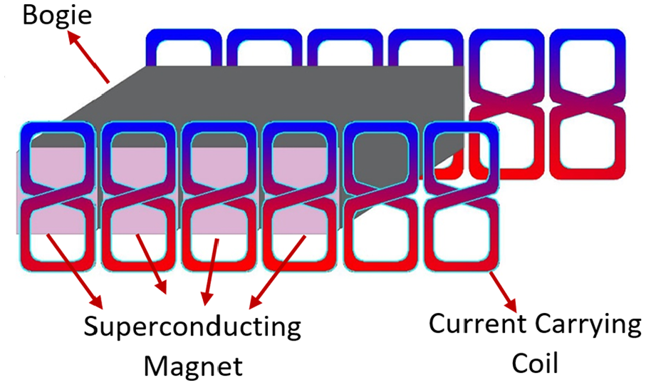
Superconductor and levitation coil arrangement on the Bogie.
Quarter-capsule vehicle semi-active suspension system nonlinear dynamic model
This paper focuses on the vertical motion of a vehicle only, so a quarter-car model, as illustrated in Figure 4, is taken for the analysis of the vertical dynamics of the suspension system as well as to design control of semi-active MR damper on the secondary suspension system.

Quarter-car model of a capsule train.
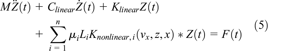
Many kinds of research have been done to find out computationally less complex and more accurate method for the analysis of nonlinear dynamic suspension system. These days, a subspace identification method becomes more popular and advantageous for the generalized parametrization of multiple-input multiple-output (MIMO) systems 10 and many researchers use this method as a millstone idea. Marchesiello and Garibaldi 11 proposed a nonlinear subspace identification (NSI). In this publication, the nonlinear parts are assumed as unmeasured internal feedback force to the linear system with particular attention to reduce the ill-condition of the system. Noel et al. 12 proposed a Grey-box nonlinear State-space modelling method, in which a two-step identification procedure with the integration of nonlinear subspace initialization and optimization is derived for the grey-box. Jie et al. 13 proposed a novel nonlinear separation subspace identification (NSSI) method. In this paper, the nonlinearity is due to the electrodynamic levitation stiffness coefficient. It depends on the vertical and horizontal position and forwarding velocity of the bogie. So that the capsule’s nonlinear dynamics of a quarter-car model is defined as a combination of linear and nonlinear parts, as shown in equation (5).
Where

Using equation (6) and Figure 3, the vertical dynamics of the quarter-car model of a capsule is expressed in state space form as in equation (7) below

Using the nonlinear separation strategy, the unknown nonlinear EDS stiffness and MR damper force terms are regarded as the internal feedback input to the linear system and it is illustrated as in Figure 5.


Feedback representation of nonlinear part (equation (6)).
Equation (8) can be represented by state space form as below

Where

The nonlinear weight term

MATLAB simulink model of a system with damper and system controller.
Semi-active suspension system
The damping efficiency of a semi-active suspension system relies greatly on its control system. Therefore, developing an efficient control algorithm is the main focus of a semi-active suspension system. In an MR damper semi-active suspension system, the system consists of two nested controllers (MR damper controller and system controller), as illustrated in Figure 7. The MR damper controller controls the amount of current or voltage input to the MR damper. A system controller computes the desired damping force for a given system condition.

General layout of semi-active suspension system controller.
Damper controller
The MR Damper controller verifies and controls the amount of input current to the MR damper by taking the relationship between the input current and an MR damper’s output force
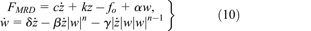
Where


Where
Using the above stated MR damper model, the MR damper controller provides the required amount of current to track the desired force signal. The MR damper controllers, proposed in many literatures, can be categorized as in the following categories, and each has advantages and disadvantages.
Heaviside Step Function (HSF): it is a feedback type an ‘on-off’ control algorithm where the applied current is either 0 or

Where:
Signum Function Damper Controller (SFDC): 20 it is a modified form of the Heaviside function method, in which under certain conditions, the input current can be switched to some discrete value below the maximum allowable amount. But still, the command input current signal is a discrete type, which is a disadvantage for this method.
Inverse Polynomial Controller: it is feed forward control law type. Chio and Lee 21 divided the nonlinear hysteretic characteristics of the MR damper into positive acceleration (lower loop) and negative acceleration (upper loop) and introduced a polynomial function of degree 6 to represent these loops and also the MR damper model. Then, Haiping et al. 22 control the current input by taking the inverse polynomial of the MR damper proposed by Choi SB et al. 23 Arias-Montiel et al. 24 also proposed a polynomial function with degree 2 to model the MR damper. But in both cases, the polynomial function model accuracy is not good as compared to the Bouc-Wen model, especially when the nonlinear hysteretic Force-velocity loop is not smooth.
Inverse MR damper Controller: It is also a feed forward control law type and the required current for a given desired force is estimated from the predefined MR damper’s invers model. Xia 25 and Boada et al. 26 proposed a modified neural network technique for the inverse dynamic model of an MR damper to predict the input current for the desired force. This technique requires a high amount of experimental data for training and validation of the network. Additionally, its time delay effect is not promising as a result of its high computational expense.
Weber 27 proposed a feedforward control law with a control-oriented mapping approach to reduce modelling effort of the inverse MR damper behaviour. The parallel, proportional and integral feedback gain control algorithm still supports the proposed forward control law to minimize the resulting force tracking error. Terzo and Russo 28 proposed a combined feedback and feed forward control algorithm for his shear mode magnetorheological device. Pang et al. 29 proposed a novel variable universal fuzzy controller. In his method he used a combined fuzzy neural network and particle swarm optimization for the computation of the required current. Sunil and Rakesh 30 showed that the semi-active suspension system using MR damper fluid based on Bingham model is better than the passive suspension system for the ride quality improvement.
Continuous State Damper Controller (CSDC): It is a feedback control type and the MR damper current is estimated based on the difference between the desired control force and the actual MR damper force. Using this algorithm, the input current signal can be varied continuously between 0 and

Where
Because of the above advantages and disadvantages, the continuous state damper controller (CSDC) is used as MR damper controller in this paper, and
System controller
There are numerous published techniques for controlling semi-active suspension system. Nagarkar et al.
32
suggested a linear quadratic regulator (LQR) to control the active suspension system of an automobile and he conclude that the active controlled suspension system is better than the passive one. Saad et al.
33
evaluated the performance of semi-active Bouc-Wen modelled MR damper with a PID controller under different disturbance inputs, and they concluded that the PID controller is efficient in increasing vehicle stability. Papkollu et al.
34
compared the performance of the active suspension system with PID and
Skyhook controller (SH): in the virtual skyhook damper, the body which is supposed to be isolated from vibration (in our case car-body), is assumed to be connected to a fixed frame (sky) as shown in Figure 8(a). Hence, the required control force applied on the sprung mass,

Where,

Skyhook damper: (a) virtual skyhook damper configuration and (b) semi-active implementation of skyhook damper.
In real situation, it is impossible to connect the moving car-body to a fixed frame. Therefore, a skyhook damping is to use a semi-active damper which is placed between sprung and unsprang mass as shown in Figure 8. A semi-active suspension system produces a control force of

However, when

Where,
Therefore, Karnopp et al. 4 modified the required skyhook force in another way in relation to the relative velocity between car-body and bogie like below

Acceleration-Driven-Damper (ADD): in this algorithm, the control factor is the acceleration signals of car-body and bogie and the required force is formulated as below

Mixed SH-ADD Controller: The performance of an SH controller is better than an ADD controller in a low-frequency domain, and ADD is better than SH in a high-frequency domain. Therefore, in a mixed SH-ADD controller the shifting factor is expressed as follows: 39

Where,
Experiment arrangement
The processor unit analyses the quarter-car model of a capsule on a MATLAB Simulink environment and sends MR damper’s ends relative displacement and input current signals to the plant unit (MR damper) through the signal transmitter. According to input signals, the plant unit (MR damper) produces the required amount of force and send it back to the processor unit. The signal flowing in both directions passes through the signal transmitter to convert it from analogue to digital or vice versa, which is appropriate for the receiver. The MR damper current driver delivers the required amount of current to the MR damper based on the signal it receives from the signal transmitter. The load cell records the produced MR damper force and transmits a signal to the transmitter. The general layout of the experimental setup is illustrated in Figure 9.
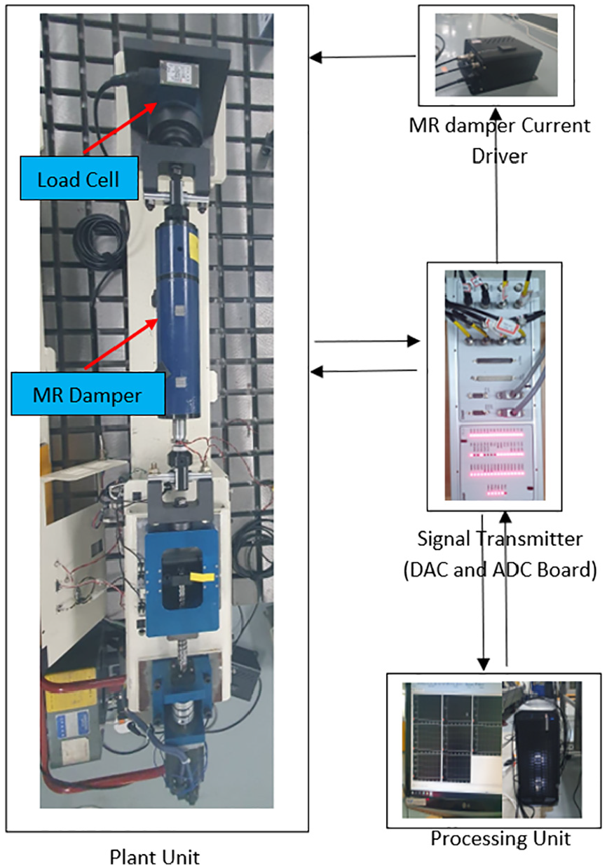
General layout of experimental setup (HILS).
Result and discussion
In this research, a quarter-car model of a hyperloop capsule dynamics is done for the analysis and performance evaluation of the SH and mixed SH-ADD semi-active suspension system. The semi-active suspension system is assumed to be consist of an MR damper with a CSDS MR damper controller and a mixed SH-ADD and SH system controllers. Parameter values of the hyperloop capsule is stated in Table 1.
Parameter values of capsule vehicle.

The guideway irregularity (input disturbance to the system) is assumed to be a white noise signal of normally distributed random number with a maximum amplitude of

Guideway irregularity.
The model’s simulation is done on MATLAB Simulink alone environment and hardware-in-loop system (HILS) environment using equations (3) and (9) and parameter values (Table 1) to evaluate the performance of the suggested semi-active suspension system controllers. Based on equation (3), the model’s electrodynamic levitation system nonlinear stiffness spring coefficient is found to be as shown in Figure 11 below, and the amount of current fed by the current controller to the MR damper with SH and mixed SH-ADD system controller is shown in Figure 12.

Nonlinear primary suspension stiffness coefficient.

MR damper controller input current for HILS system: (a) for SH system controller and (b) for SH-ADD system controller.
The time domain and frequency domain displacement responses of sprung and unsprung masses under the above two simulation environments are shown in Figures 13 and 14 below. As seen from the time-domain responses of Figures 13 and 14, the displacement response magnitude using the MATLAB Simulink environment is smaller than the HILS environment. The difference comes from the fact that the theoretical MR damper modelling equation may exaggerate the output performance of the MR damper and there is no time lag in the simulation (theoretical) analysis. In the MATLAB Simulink environment, we express the MR damper with the proposed model, which is not 100% identical to the actual MR damper property, but in the HILS environment, we are using the actual MR damper, and there is no MR damper modelling error with this arrangement. But in both simulation environments, the semi-active MR damper performance is better than the passive MR damper. Passive MR damper here in this paper means an MR damper with 0 current input. The performance of the designed semi-active suspension system under the above-stated input disturbance is evaluated using MATLAB Simulink and HILS environments. We assume a capsule’s sprung mass vertical-displacement in MATLAB Simulink and HILS environment as an evaluation criterion. Taking the frequency from 0 to 8 Hz range, the root-mean-square (RMS) value of vertical displacement of the sprung mass is shown in Table 2 for passive and semi-active (under SH and SH-ADD controllers) secondary suspension systems.
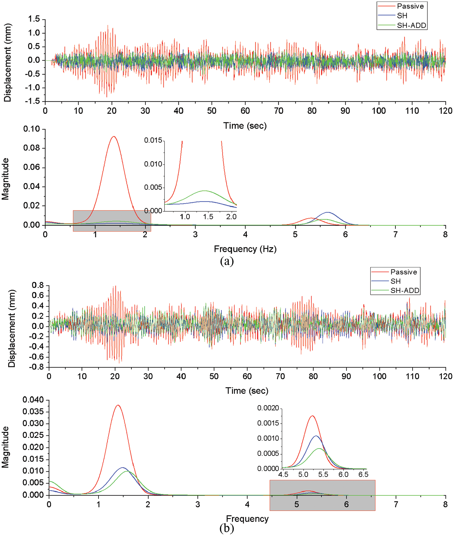
Time and frequency domain of Capsule’s sprung mass vertical displacement: (a) HILS environment and (b) MATLAB simulink environment.

Time and frequency domain of Capsule’s unsprung mass vertical displacement: (a) HILS environment and (b) MATLAB simulink environment.
RMS value of capsule’s sprung mass vertical displacement under MATLAB Simulink and HILS environment.
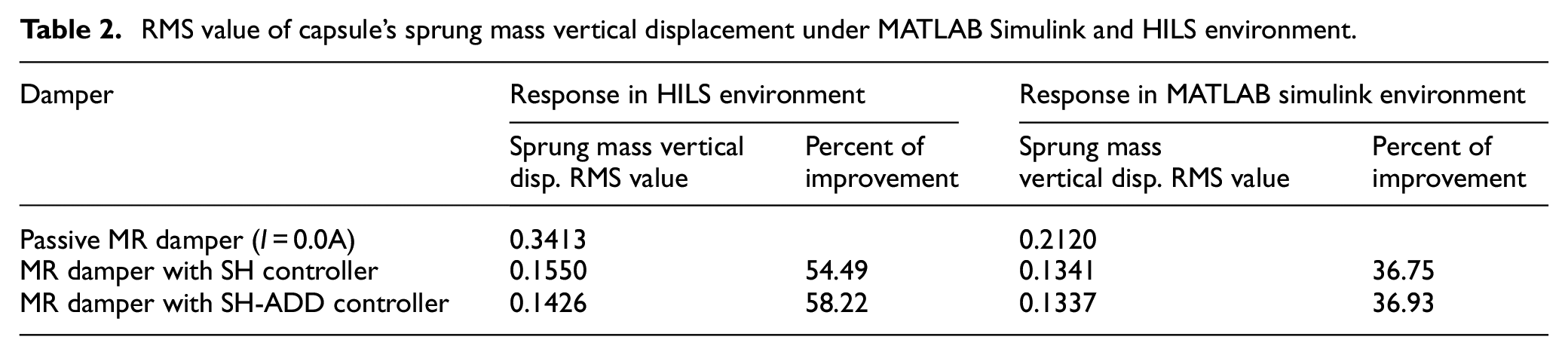
From Figure 13(a), we can prove that the SH system controller is better than the passive MR damper at the lower frequency domain and worse than the passive MR damper at the higher frequency region, but the mixed SH-ADD system controller performances better than the passive MR damper for all frequency values. Even though the performance of the mixed SH-ADD system controller is a little bit lower than the SH controller at the lower frequency region, the overall performance is better than the SH controller, as shown in Table 2. Taking the RMS value in both MATLAB Simulink and HILS environment vertical displacement response, the SH Controlled MR damper performance is improved by 54.49% in the HILS environment and 36.75% in the MATLAB Simulink environment relative to the passive MR damper performance, and the mixed SH-ADD Controlled MR damper performance is improved by 58.22% in the HILS environment and 36.93% in the MATLAB Simulink environment.
The sprung mass’s maximum vertical displacements at the vicinity of the two resonance frequencies, under the HILS environment, are stated in Table 3. The tabulated values show that at the first resonance frequency, both SH-controller and SH-ADD controller has a better vibration reduction effect than the passive Mr damper. At the second resonance frequency, the SH-controller is not good in reducing the vibration compared to the passive damper but the mixed SH-ADD controller is still good at this vicinity also.
Peak vertical displacement of sprung mass at the two resonance frequencies.

Conclusion
This paper has adopted a mixed SH-ADD and skyhook system controllers to control a viscous MR damper suspension system of a hyperloop capsule train. The performance of a semi-active suspension system highly relies on its control algorithm. The control algorithm shall be as simple as possible with good tracking ability to decrease the response time. The levitation system of the capsule is a nonlinear EDS system. Hence, the nonlinear vertical dynamics of the quarter-car is modelled by NSI method. The dynamic performances of both controllers are evaluated under MATLAB Simulink and hardware-in-loop system (HILS) environment. As illustrated in Figure 13(b) and Table 3, however, the skyhook-controlled MR damper performance is much better than the passive damper in the vicinity of first resonance frequency, its performance is worse than passive damper at the second resonance frequency. To improve the performance of the skyhook control system at higher frequency domain the mixed SH-ADD control algorithm is adopted in this paper. The mixed SH-ADD controlled MR damper performance is better than passive damper at all frequency domains. Taking RMS values of HILS response of a sprung mass (Table 2), the skyhook-controlled MR damper improves the vertical displacement of the sprung mass by 54.49%, and the mixed SH-ADD-controlled viscous MR damper improves by 58.22% relative to the passive damper vertical displacement. By providing a small amount of energy
Footnotes
Handling Editor: James Baldwin
Declaration of conflicting interests
The author(s) declared no potential conflicts of interest with respect to the research, authorship, and/or publication of this article.
Funding
The author(s) disclosed receipt of the following financial support for the research, authorship, and/or publication of this article: This paper has been supported by Core Technology Development of Subsonic Capsule Train research project, Korea Railroad Research Institute, Korea as part of grant no. PK2101A1.