
Abstract
Water lubricated stern bearings (WLSBs) are the critical component of ship propulsion system and have important effect on navigation safety. Operating temperature plays a main role on the performance of WLSBs. This paper aims to investigate the effect of operating conditions on bearing temperature characteristics under hydrodynamic lubrication. A novel CFD simulation method developed to improve calculation accuracy. Finite difference method was used to decrease the error of geometric modeling while the experiment and experimental correction formula were exploited to obtain improved boundary conditions. Based on the new method, the effects of operating conditions on temperature characteristics for two typical WLSBs were studied, and mechanisms of bearing temperature field evolution were discussed. Results show that the max friction coefficient appears when bearings are in low velocity and low load condition. Total heat flux density is a function of linear velocity, pressure and friction coefficient. Max temperature of bearing at 0.4 MPa decrease along with increased velocity, while decrease first and then increase at 0.2 MPa. Moreover, peak temperature appears at eccentric side and beyond minimum water film thickness position about 4–40°. High temperature area mainly located at the position of 80–140° in circumferential direction and 0.2–0.13 m in axial direction. With the increase of inlet water velocity, the max temperature of bearing changes slightly. It is appropriate to set the inlet velocity at 2 m/s to obtain better cooling performance. This work can provide theoretical basis for the operation monitoring of WLSBs and the development of new materials.
Introduction
The interests in environment-friendly technologies have stimulated by the strict regulations and the enhancement of environmental awareness, particularly in oil-lubricated bearings replaced with water lubricated ones. Water lubricated bearings have been widely used in hydroelectric turbine, 1 nuclear main pump, 2 machine tool 3 and other industrial equipment with the advantages of low cost, simple structure, environmental friendly and satisfied tribological properties. It is also popular in ship propulsion system due to its good adaptability to shaft misalignment caused by manufacturing error, improper installation and hull deformation. Polymer materials are the typical bush materials used in WLSBs due to wear resistance, vibration damping and anti-corrosion properties. To improve the properties of WLSBs, some scholars carried out a number of distinguished researches in polymer materials.4,5 However, most of the current studies launched at room temperature without considering the influence of temperature variation. Researches show that the minimum water film thickness of bearing will decrease with the increase of temperature,3,6 so do the hardness and elastic module of bush materials.7,8 However, the wear rate, friction coefficient, vibration and noise will increase along with the temperature.9–12 Researches 13 indicated that the average friction coefficient of UHMWPE increases by 65.96% under 720 h, 80°C aging condition compared with the original sample. Moreover, most bush materials of WLSBs are semi-crystalline polymer, and their operating life will decrease exponentially with the increase of temperature. 14 The accelerated aging under high temperature can cause a fracture of molecular chains and chemical oxidation reaction that correlate with the deterioration of materials.13,15 The water intake of bearings under high operation temperature should also be considered. Luca 16 found that the weight of UHMWPE composites continued to increase after 112 days of immersion into 80°C water, while the samples were approximately saturated since the seventh exposure day into room temperature water. The excessive water swelling of bush materials can decrease the running clearance, leading to the lock between bush and shaft. 17 Some researches considering temperature variation have conducted but the temperature range under study is diversify.7,8,10,11 The working conditions have a significant effect on the bearing temperature characteristics. Studies show that the surrounding water temperature increment of WLSBs at 0.4 MPa can reach 50°C after an hour operation while it is less than 20°C at 0.2 Mpa. 9 In a word, it is essential to study the temperature characteristics of WLSBs under different operation conditions.
The full circumferential temperature distribution usually gained by numerical calculation which can be achieved by two methods, one is to solve Reynolds equation and energy equation, and the other is to solve N–S equation and energy equation directly. The former is only applicable to laminar flow of lubricants and ignores the effect of inertial force, volume force and heat conduction in the direction of film thickness.18,19 For WLSBs, the bearing clearance is larger than that of traditional bearings. Besides, a number of water grooves usually arranged on the lining. These issues make the cooling water in turbulent state and the effect of inertial force could not be ignored.3,20,21 Therefore, the latter is more suitable to study the temperature characteristics of WLSBs. The commercial software FLUENT is widely used in fluid flow simulation, which can obtain the three-dimensional temperature distribution of water film22,23 and is more accurate than the solution of Reynold equation and energy equation simultaneously. 19
It is very important to set boundary conditions during the calculation. However, some cases simplified the rotating shaft as heat source with constant temperature,18,23 which ignored the heat taken away by the lubricants. There are also some scholars simplified the shaft surface as adiabatic surface 24 with all the heat are absorbed by lubrication film. In fact, both the heat conduction and heat convection should not overlooked because the shaft sleeve of WLSBs is usually made of copper alloy with a high thermal conductivity and the cooling water may be in turbulent state. Besides, geometry modeling is essential to the calculation, but it is difficult to obtain the geometry parameters of water film. In conclusion, it is crucial to develop a valid method to set boundary conditions and establish water film model.
For safety and reliability reasons, WLSBs usually designed in hydrodynamic lubrication. It should admitted that the excessive friction heat occurred due to the severe asperity contact under some extremely conditions. Nevertheless, these situations are not the ordinary state and the excessive friction heat will take away quickly when the hydrodynamic lubricate film formed. In this study, a novel approach proposed to investigate temperature field evolution of WLSBs under hydrodynamic lubrication. Two common applied WLSBs, Thordon XL, and SF-1, were used in this research. The structure diagram of whole research work can see in Figure 1. Firstly, the friction coefficient obtained on the test bench, and Gnielinski formula modified to calculate the heat transfer resistance of cooling water. Besides, the distribution model of bearing heat flux was established. Based on the experiment results and mathematical model, the effect of operation conditions on the heat flux density can be evaluated. In addition to this, Reynold equation, solved by finite difference method (FDM), was used to establish the geometry models of water film. Finally, the influence of operating conditions on the bearing temperature characteristics can be investigated. This research can provide theoretical basis for operation monitoring of bearings and development of new bush materials.
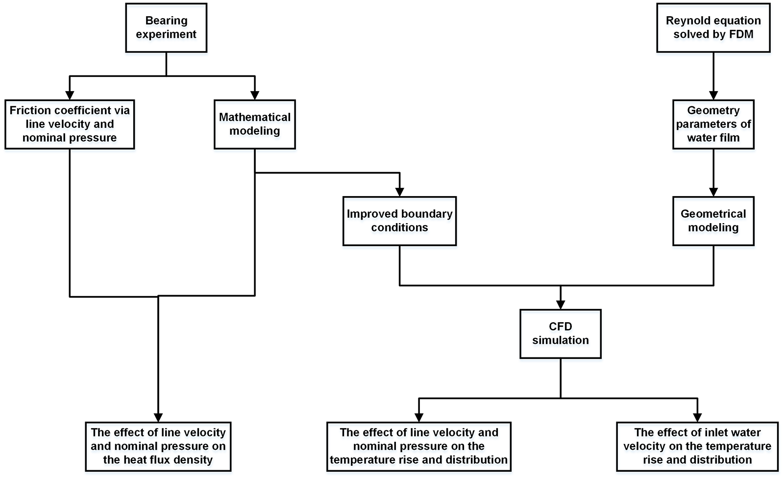
Structure diagram of the whole research work.
Experiments
Test bearing and shaft
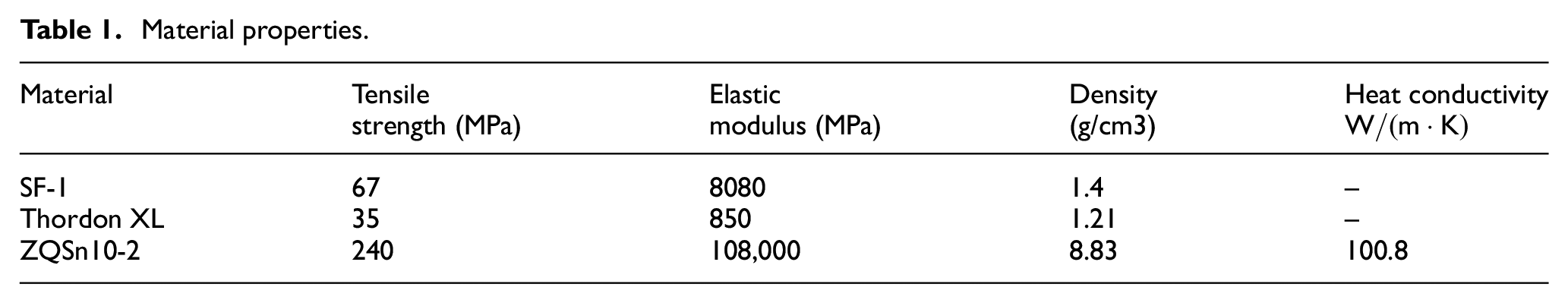
WLSBs are quite different from traditional journal bearings, especially its structure and lining material. The sleeve material of two test bearings is brass and the lining is SF-1 and Thordon XL respectively. Eight grooves arranged in the lining to improve the cooling and lubricated performance. The test shaft paired to the bearing made with 45 steel, and the shaft journal covered by ZQSn10-2 sleeve, as shown in Figure 2(a). Test bearing schematic and parameters can see in Figure 2(b), Tables 1 and 2.

Friction pair schematic and experiment apparatus: (a) test shaft schematic, (b) test bearing schematic, and (c) experiment apparatus.
Material properties.
Structure parameters.

Experimental apparatus and procedures
Experiments conducted on the marine stern bearing device SSB-100, which designed by Wuhan University of Technology as shown in Figure 2(c). During test, middle journal loading method is conducted to ensure the load evenly exerted on the test bearing and the force sensor is applied to indicate the loading force N of hydro cylinder. Cooling unit can adjust the flow of tap water to ensure good lubrication and cooling. All the parameters were transmitted to a computer for display and further analysis by the multichannel analyzer. Finally, friction coefficient f and nominal pressure
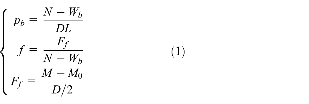
Further, the friction coefficient f can be expressed as equation (2)

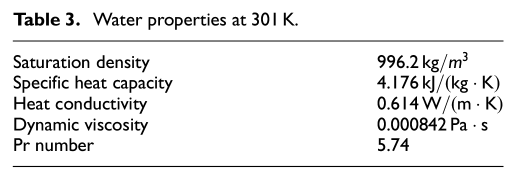
In order to keep dimensional stability, all the test bearings submerged into water for two months before experiment. The room temperature is 301 K constantly and the cooling water properties shown in Table 3.
Water properties at 301 K.
Experimental procedure was as follow: First, the applied nominal pressure set to 0.2 MPa and the shaft velocity established at 0.48 m/s. The cooling water flow Q set to 30 L/min according to the Thordon Instruction. This working condition maintain about 6 h for each bearing to ensure enough running in. After running in period, the shaft velocity set to 0.8, 1, 2, 3, 4, 5, 6, 7, 8, 9, 10 m/s when the nominal pressure set to 0.05, 0.1,0.2,0.3, 0.4, 0.5, 0.6 MPa respectively. All the working condition last 15 min before record parameters.
Geometric modeling
Fundamental equation
Take cooling water as incompressible fluid and ignore the water properties change,

Then, the dimensionless Reynold equation can be written as equation (4)
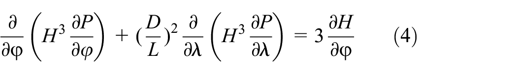
The boundary condition was set to Reynold boundary condition.
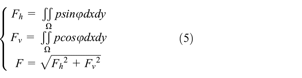
The bearing capacity of water film is equation (5):
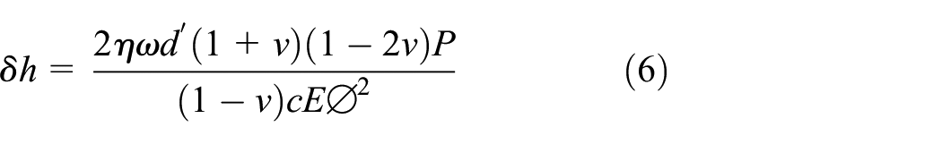
Water grooves ignored in the FDM calculation since grooves mainly distributed on the upper part, which is not the main working area. According to the Winkler assumption, plastic liner under load is equivalent to many parallel springs, which fixed between the bearing sleeve and water film. Dimensionless elastic deformation of lining can be written as equation (6):
So

Numerical scheme
The inner surface of bearing can evenly divide into

Dimensionless coefficients

The pressure iterate procedure will stop when pressure convergence met equation (10).

The procedure stops when bearing capacity reached according to equation (11).

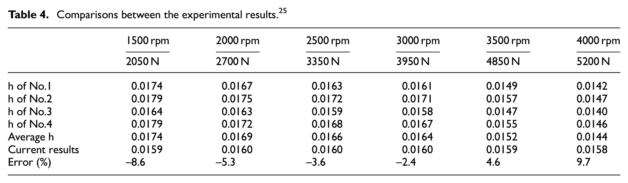
FDM validation and geometry modeling
The water film thickness
Comparisons between the experimental results. 25
The calculated pressure distribution curves also validated. We can see from Figure 3 that the numerical results match well with the literature. It is believed that the numerical procedure is credible.

Comparison of the pressure by literature and calculated results: (a) pressure distribution of the bearing mid-plane 25 and (b) pressure distribution of the bearing mid-plane (Calculated results).
Based on the calculated results, the geometry models of water film can establish.
Improved boundary conditions and CFD model validation
Improved boundary conditions
When the bearings are in hydrodynamic lubrication, the friction force is equal to the shear force between water molecules, so the friction heat generated in the water film. Because of the low heat conductivity of polymer lining, 26 all the friction heat exerted on the interface between water film and shaft sleeve.
Assumed all the power consummation were converted to friction heat, we can obtain the total friction heat flux density

The heat conductivity through shaft sleeve can be simplified as heat conduction of cylindrical wall, so thermal resistance

The cooling principle of WLSBs is differ from the law of heat convection for circular tube because of the rotate shaft. However, we can make a correction of the cooling water velocity to meet the requirements. Assumed the cooling water is Newtonian fluid, ignored the influence of gravity and boundary slip, the average velocity in the circumferential direction is
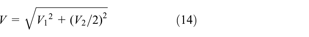
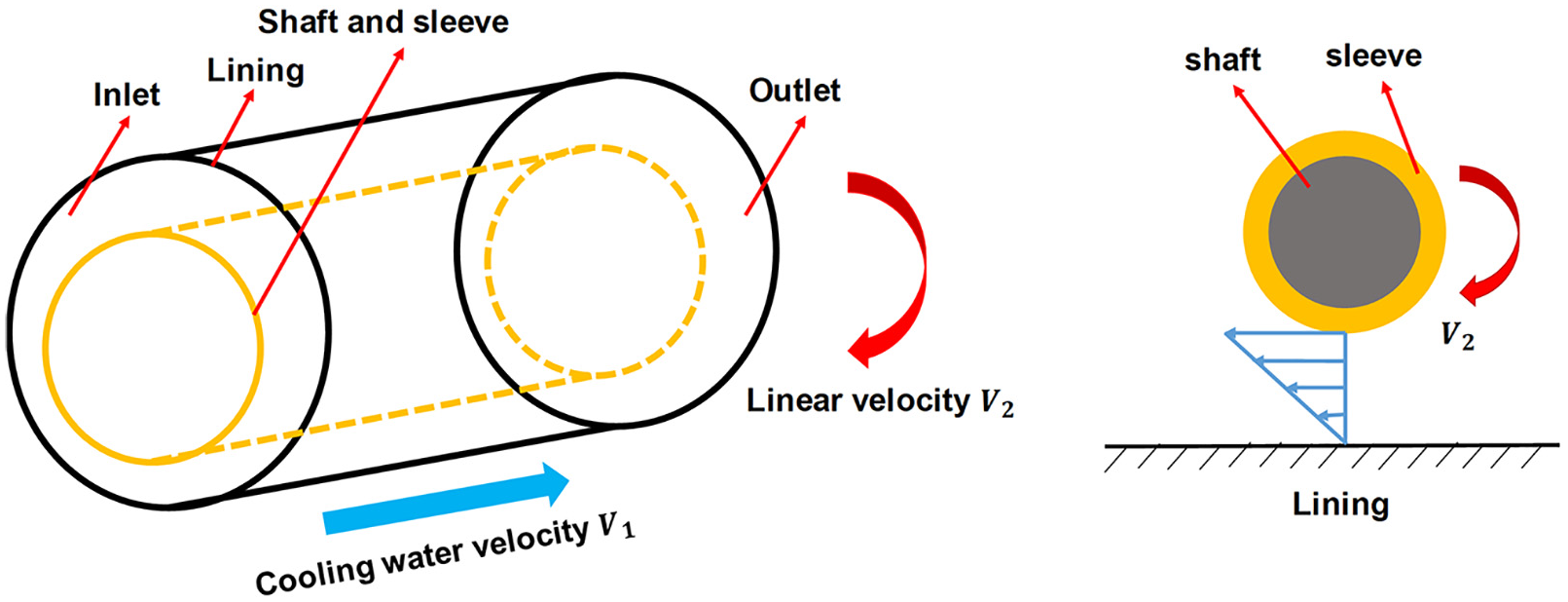
Velocity correction schematic
The inaccuracy of experimental correlations formula for turbulent heat transfer is often ±20% or even ±25%, while the max deviation between Gnielinski formula and experiment results is within ±10% in most cases. 27 Therefore, the Gnielinski formula was chosen to calculate turbulent heat flow capacity of water film, as shown in equation (15)

The total friction heat will dissipate by cooling water and shaft sleeve, so the heat flux density
The lining and shaft sleeve were separated by water when bearing is in hydrodynamic lubrication. Due to the high heat conductivity, shaft sleeve temperature can see constant. Water film inside surface was set to rotating wall. Besides
CFD model validation
In order to validate the simulation model, a comparison between literature 28 and calculated results had been conducted, as shown in Figure 5. It is notable that the error of partial grooved bearing is smaller than the full grooved bearing, especially when the inlet velocity is high. This may cause by the definition of flow condition. As we know, the total heat exchange of groove region is much higher than the non-groove region because the heat transfer coefficient of turbulent flow is bigger than laminar flow. The model developed in this study treat the groove and non-groove region as a whole to calculate Reynold number, so the total heat exchange is smaller than actual condition. The more groove number of bearing, the bigger error between the actual condition and simulate results. Generally, whatever the partial grooved bearing or the full grooved bearing, the max temperature calculated by this new model match well with the results of literature.

Comparison between literature 24 and calculated results.
Results and discussion
Effects of linear velocity and nominal pressure on the friction coefficient
Figure 6(a) and (b) show that the

Friction coefficient
As shown in Figure 6(c) and (d), friction coefficient
Effect of linear velocity and nominal pressure on the total heat flux density of bearing
Based on the equations (12) and (2), we can obtain equation (17)

It is obvious that total heat flux density
Figure 7(a) and (b) show that total heat flux density
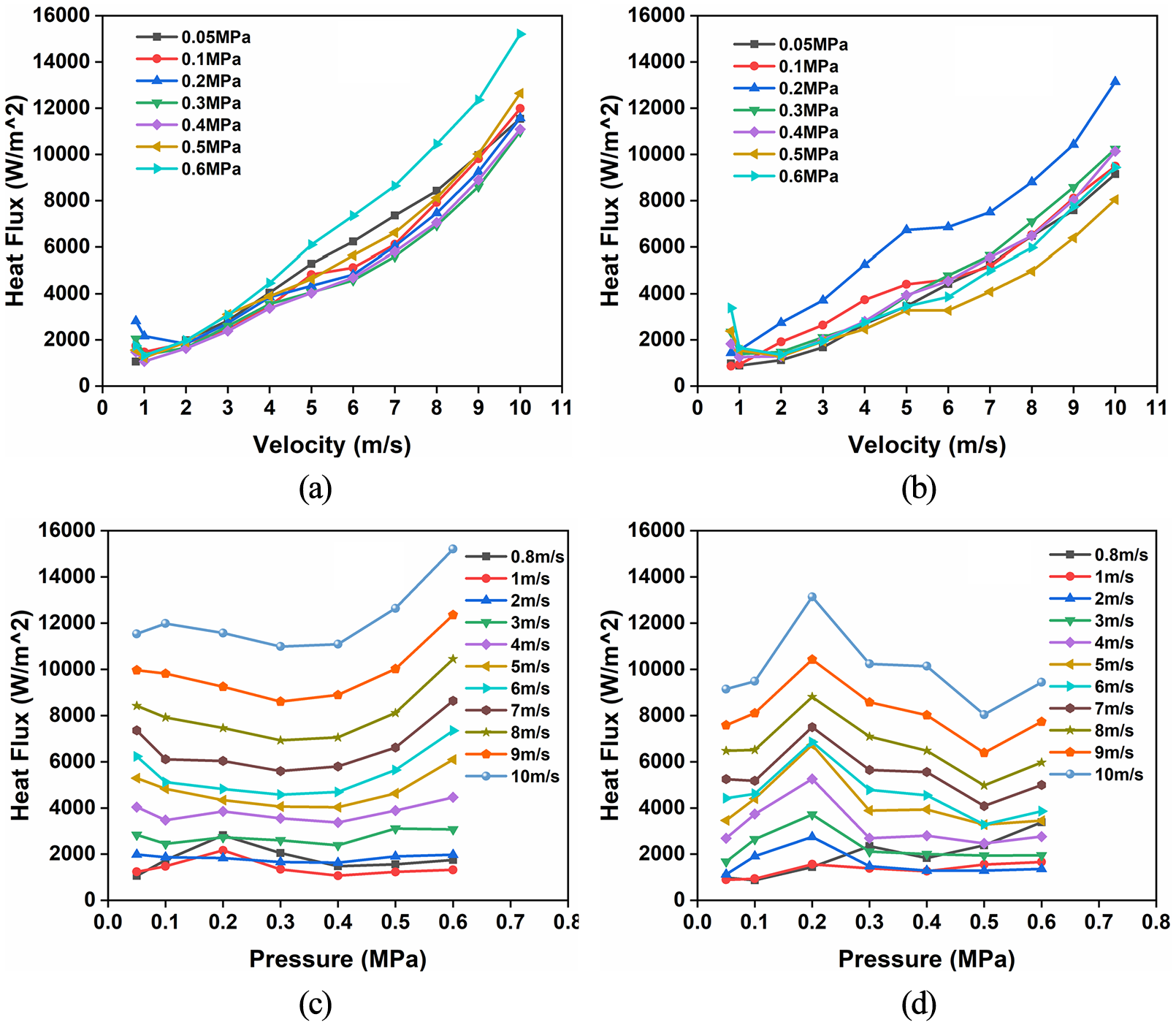
Total heat flux density
Figure 7(c) and (d) show that the variation of
Effect of linear velocity, nominal pressure on the bearing temperature characteristics
The results of FDM show that minimum water film thickness
In this paper, it regarded as light working condition when the bearing is at 0.2 MPa and 4–10 m/s. Meanwhile it studied as heavy working condition when the bearing is at 0.4 MPa and 5–10 m/s. Based on the Thordon Instruction, cooling water inlet velocity
The max temperature obtained by CFD analysis and the average temperature calculated by Equation (18).
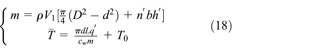
Figure 8(a) shows that the max temperature at 0.4 MPa decrease along with

Effect of linear velocity on max temperature, average temperature, heat transfer capacity and min waterfilm thickness: (a) maximum temperature, (b) average temperature, (c) heat flow, and (d) minimum thickness.
Figure 9(a) and (b) present the axial temperature distribution of min water film area for SF-1 and Thordon respectively. It can see that cooling water temperature increased sharply in inlet, then maintain at a high level and finally decrease in outlet rapidly. This attributed to the entrance effect of heat transfer. Meanwhile high temperature area decrease along with

Temperature variation in axial direction and in circumferential direction of bearings: (a) axial temperature variation of SF-1 bearing, (b) axial temperature variation of Thordon bearing, (c) circumferential temperature variation of SF-1 bearing, and (d) circumferential temperature variation of Thordon bearing.
Effect of cooling water inlet velocity on the bearing temperature characteristics
The temperature rise is the biggest for SF-1 bearing when it is at 0.2 MPa pressure, 4 m/s velocity. While Thordon bearing is in the worst cooling condition at 0.4 MPa pressure, 5 m/s velocity. The range of 1-5m/s studied to evaluate the effect of cooling water inlet velocity on the bearing characteristics.
As shown in Figure 10, max temperature decrease first, then increase and finally decrease along with cooling water inlet velocity

Effect of inlet velocity on max temperature, average temperature, heat transfer capacity of water film: (a) max temperature, (b) average temperature, and (c) heat transfer capacity.
Figure 11(a) and (b) present that the temperature increased sharply in the inlet, then maintain at a high level and finally decrease in the outlet rapidly. The temperature peak and high temperature area in axial direction move to the outlet side with the increase of

Temperature variation in axial direction and in circumferential direction of bearings: (a) axial temperature variation of SF-1 bearing, (b) axial temperature variation of Thordon bearing, (c) circumferential temperature variation of SF-1 bearing, and (d) circumferential temperature variation of Thordon bearing.
Conclusion
A novel CFD simulation method developed based on the improved geometry model and boundary conditions. Effects and mechanisms of working conditions on temperature characteristics for two WLSBs were evaluated. From the results, following conclusions can summary:
With the increasing velocity, friction coefficient drops dramatically first and then increase slowly. For given operating conditions, increasing nominal pressure will decrease friction coefficient and it will go to stabilize when the pressure is high. The friction coefficient curve of SF-1 is more moderate due to the high elastic module. Besides, the max friction coefficient appears when bearings are in low velocity and low load condition.
The variation of total heat flux density is the result of competition among linear velocity, friction coefficient and nominal pressure. With the increasing velocity, total heat flux density decreases first and increases after with a turn point at 1 m/s. For SF-1 bearing, the heat flux density increases first, then decreases and finally increase along with the pressure. For Thordon bearing, heat flux density is stable when the pressure is lower, while shows an approximately linear increase along with pressure when the pressure is higher. Thordon bearing is more suitable to low load condition while SF-1 bearing is the better choice at high load condition.
Bearing temperature characteristics determined by the heat transfer capacity and water film thickness. Max temperature of water film at 0.4 MPa decrease along with increased velocity, while decrease first and then increase at 0.2 MPa. Besides the peak temperature appears at eccentric side and beyond min water film thickness position about 4–40°. The high temperature area mainly located at the position of 80–140° in circumferential direction and 0.2–0.13 m in axial direction.
With the increase of inlet water velocity, max temperature of bearing changes slightly. It is appropriate to set the inlet velocity at 2 m/s to obtain better cooling performance. Temperature peak and high temperature area in axial direction move to the outlet side with the increasing cooling water inlet velocity. Besides, high temperature area will decrease along with the cooling water inlet velocity.
Footnotes
Appendix
Acknowledgements
The authors want to express their sincere thanks to Professor Zhenglin Liu and Doctor Xingxin Liang for their help.
Handling Editor: James Baldwin
Declaration of conflicting interests
The author(s) declared no potential conflicts of interest with respect to the research, authorship, and/or publication of this article.
Funding
The author(s) disclosed receipt of the following financial support for the research, authorship, and/or publication of this article: This work is supported by the National Natural Science Foundation of China (51605248) and the Fundamental Research Funds for the Central Universities (WHUT: 2020-zy-104).