
Abstract
One degree-of-freedom (DOF) jumping leg has the advantages of simple control and high stiffness, and it has been widely used in bioinspired jumping robots. Compared with four-bar jumping leg, six-bar jumping leg mechanism can make the robot achieve more abundant motion rules. However, the differences among different configurations have not been analyzed, and the choice of configurations lacks basis. In this study, five Watt-type six-bar jumping leg mechanisms were selected as research objects according to the different selection of equivalent tibia, femur and trunk link, and a method for determining the dimension of the jumping leg was proposed based on the movement law of jumping leg of locust in take-off phase. On this basis, kinematics indices (sensitivity of take-off direction angle and trunk attitude angle), dynamics indices (velocity loss, acceleration fluctuation, and mean and variance of total inertial moment) and structure index (distribution of center of mass) were established, and the differences of different configurations were compared and analyzed in detail. Finally, according to the principal component analysis method, the optimal selection method for different configurations was proposed. This study provides a reference for the design of one DOF bioinspired mechanism.
Keywords
Introduction
Micro jumping robot has the characteristics of short take-off time and high acceleration, and how to make the jumping robot have the advantages of good controllability and high stiffness is one of the focuses of current research.1,2 The reason why high stiffness is desirable is that the jumping leg mechanism will collide with the ground when landing, and the higher the stiffness of the jumping leg, the stronger the ability of the jumping leg to resist elastic deformation. In order to solve existing problem, on the basis of existing bionic jumping mechanisms and flexible jumping mechanisms.3–5 a one degree-of-freedom (DOF) mechanism is introduced into the design of jumping robots.6,7 One DOF bioinspired mechanism can approximately reproduce the motion process of the biological leg with only one drive, which is of great significance to its research.
Most of the existing research focuses on the one DOF jumping leg with four-bar mechanism. For example, the bioinspired jumping robot designed by Li et al. 8 has one DOF four-bar jumping leg. The link length of jumping leg was determined based on the structural parameters of biological leg, and the robot can take off quickly. The jumping leg of bioinspired jumping robot designed by Zhang et al.9,10 of Southeast University is also a four-bar mechanism. The average jumping height and jumping distance were 99.1 and 72.7 cm on a smooth surface, respectively. In particular, the four-bar mechanism has been widely used in flexible-driven jumping robots due to its simple structure. For example, Institute of Advanced Machinery and Design of Seoul National University has continuously studied a miniature jumping robot driven by shape memory alloy (SMA), and the leg mechanisms of the robot are four-bar mechanisms.11–13 However, due to the limitation of its configuration, the four-bar jumping leg mechanism is difficult to make the robot have expected performance, such as good jumping stability and specified jumping trajectory. Therefore, some researchers began to study one DOF six-bar or even eight-bar jumping mechanism. Zhang et al. 14 of Beijing University of Technology designed a jumping robot with the Stephenson II type six-bar jumping leg, and a mechanism design method based on jumping stability (including kinematic and dynamic stability) was proposed for a bioinspired robot. The eight-bar mechanism was used as the jumping leg for the jumping robot “Salto” designed by Haldane et al.15–17 The robot has good agility and high jumping frequency, and can achieve the expected jumping trajectory. This jumping robot has been developed for many generations and has good jumping performance in rugged terrain. The eight-bar mechanism is also used for the single-actuator continuous hopping robot design by Bai et al. 18
Compared with four-bar mechanism, six-bar or eight-bar mechanism has more abundant configurations.19,20 According to the design requirements, different basic configurations can evolve a large number of different mechanisms. However, the design of existing six-bar or eight-bar jumping mechanisms depends on experience. The differences among different configurations are not compared, and how to choose the mechanism that meets the requirements from a large number of configurations is also a problem that needs to be solved.
In existing studies, the comparison of different configurations focuses more on parallel mechanisms.21–24 For example, several Parallel Kinematic Mechanisms (PKMs), namely a 4-UU mechanism, a spherical 5-bar mechanism and a spherical 6-bar mechanism, were analyzed by Divya et al., 21 and the best way to relocate the actuators (inertial load) was studied to reduce the share of the motive power required to drive the robot’s links, with the aim of increasing its payload-to-weight ratio. A class of 3 DOF parallel manipulators belonging to the 3-[PP]S family were compared by Abhilash et al. 25 with singularity-free orientation workspace, parasitic motions within that workspace and complexity indices as performance indices. Yu et al. 26 compared two DOF pointing mechanisms, including the gimbal structure and the 1-RR&2-RRR spherical parallel mechanism (SPM), and distinctive motion characteristics for three mechanisms can be effectively obtained. The comparison study for one DOF mechanisms is relatively few. Zhang et al. 6 compared 2 one DOF four-bar jumping leg models based on the jumping performance evaluation indices, which include the mechanical property, body attitude, jumping distance, and environmental effect. “Environmental effect” means the two contact points between the bilateral jumping legs and the ground are not on the same level due to rough terrain, and the distance of the two fixed coordinate system of left leg is 1.8 cm lower than that of the right leg along the vertical direction. Two six-bar mechanism were compared by Lv et al. 27 to make the mechanism of shaper more reasonable taking the variation of displacement, velocity, and acceleration as the study object. “Make the mechanism of shaper more reasonable” means the velocity of plough head of the shaper should be as stable as possible in order to improve the surface roughness and extend tool life. The above comparison methods for different mechanisms provide a reference for this study.
However, for the one DOF jumping leg, there are still the following problems to be solved. (a) The mapping relationship between heterogeneous models (that is the mapping relationship between multi-DOF series leg of the locust and one DOF jumping leg of the jumping robot) has not yet been established. It means that the method of determining the link length needs to be put forward to ensure that different configurations are analyzed under the same standard. (b) How to establish a mathematical model for the robot in take-off phase and establish an index system covering the main performance of jumping robot has not been studied yet. (c) Faced with the difference in performance among different configurations, comprehensive evaluation needs to be studied to provide reference for optimal selection of different configurations.
Taking Watt-type six-bar mechanism as the research object in this study, a method to determine the link length of the mechanism is put forward, and the kinematics, dynamics and structure indices of five different configurations are studied based on mathematical models. Finally, the optimal selection for different configurations is given. This study provides a reference for the design of one DOF bioinspired mechanism.
Determination of link length
Configuration design
The six-bar mechanism has abundant configurations and acceptable complexity, and it is one of the best choices for bioinspired jumping robots. “Abundant configurations” means the one-DOF six-bar mechanism has two forms: Watt Type (including Watt-1 Type and Watt-2 Type) and Stephenson type (including Stephenson-1 type, Stephenson-2 type and Stephenson-3 type), while the one-DOF four-bar mechanism has only one form. “Acceptable complexity” means the configuration of one-DOF six-bar mechanism is more complex than that of one-DOF four-bar mechanism, while it is simpler than that of one-DOF eight-bar mechanism. Therefore, the one-DOF six-bar mechanism is a better choice. Six-bar mechanism has two basic configurations: Watt-type and Stephenson-type. In this study, taking Watt-type six-bar mechanism as an example for analysis, and it is assumed that in the mechanism, all joints are rotary. It is worth noting that the analysis method is also applicable to Stephenson-type six-bar mechanism. The kinematic chain atlas and topographical structure of the Watt-type six-bar mechanism are shown in Figure 1(a) and (b), respectively. Links 2 and 5 are three-pair links, and the others are two-pair links. Different configurations can be obtained by selecting different links as initial tibia, femur, and trunk. 28 It is necessary to consider whether the link is two-pair or three-pair link and whether the selected two links are adjacent to each other. For example, for configuration 1, a two-pair link and a three-pair link connected to it are selected as initial tibia and femur, and a two-pair link is selected as trunk. According to the above method, nine possible configurations can be obtained, as shown in Figure 1(c), and the point OC is the center of mass of the robot.

Different configurations of six-bar jumping leg with Watt-type as the basic configuration: (a) kinematic chain atlas of the Watt-type six-bar mechanism, (b) topological structure of the Watt-type six-bar mechanism, and (c) nine possible configurations.
For different configurations, the primary selection can be carried out. The jumping performance of the robot needs to be analyzed by modeling, so only the structure is considered. It can be known from Figure 1(c) that the equivalent tibias of configuration 6-9 consist of only one link, and most of the links are concentrated in the equivalent femurs. This makes the mass distribution of the jumping leg seriously unbalanced, affecting the jumping stability of the robot. Therefore, only configurations 1-5 are considered in the comparative study. It is noticed that the comparison and optimal selection method presented in this paper can also be applied to configuration 6-9.
Dimension determination
The dimension of the jumping leg for different configurations should be determined, and this is the basis for comparing different jumping legs. 29 Because locust has highly-developed hind legs and is very good at jumping, 30 taking motion laws of jumping leg of locust in the take-off process as reference, the dimension of jumping leg of the robot should satisfy the following constraint conditions. 31 (a) The relative rotation angle γ1 of the equivalent tibia and femur of jumping robot and the angle θ1 between the tibia of the robot and the horizontal direction should have a large change range, which are the basis for a robot to take off normally. (b) The position of the center of mass of the robot (XOC, YOC) during the take-off process should be similar to the trajectory of center of mass of locust. According to the take-off process of the locust. 14 (Figure 2(a), these positions are chosen by considering uniform time steps during take-off process), the data of the constraint conditions are shown in Figure 2. γs is the angle between tibia and femur of the locust, θs is the angle between the tibia of the locust and the horizontal direction, and (X, Y) is the coordinate of the center of mass of the locust.

Take-off process of the locust and change of jumping leg of the locust: (a) jumping sequence of the locust and (b) change of position and attitude of jumping leg of locust.
The link length of jumping leg can be determined by the optimization method so that the one DOF jumping leg can approximately reproduce the jumping process of locust. The kinematic model is established first by taking configuration 5 as an example. The schematic of the configuration 5 is shown in Figure 3. The origin of coordinate system M5-XM5YM5 is located at point M5 (subscript 5 represents configuration 5), which is the contact point between jumping leg and ground. The direction of XM5 axis is horizontal to the right, and the direction of YM5 axis is vertical to the upward. The jumping robot is driven by spring. Its one end is connected with link E5F5 at Q5, and the other end is connected with link D5E5 at P5. Besides, the take-off direction line in Figure 3 means the trajectory of the center of mass of the robot. Since the take-off time of the robot is short (less than 100 ms), the trajectory of the center of mass is generally considered to be a straight line. In particular, the take-off direction line is not a connection between point M and center of mass OC.

Schematic of configuration 5.
The coordinate of the center of mass of the trunk OC-5 in the coordinate system M5-XM5YM5 can be expressed as
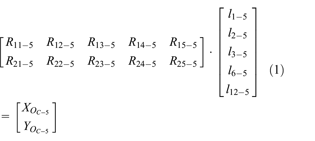
where,

where, (XOC-5, YOC-5) is the coordinate of the center of mass of the trunk for the robot in the coordinate system M5-XM5YM5, and it can be given according to experience. l1-5 (l2-5, l3-5, l6-5, l12-5) is the length of link M5E5 (D5E5, C5D5, B5C5, B5OC-5). θ1-5 is the internal angle between link E5M5 and positive direction of XM5 axis. γ2-5 (γ6-5, γ7-5) is the internal angle between link D5E5 (B5C5, A5B5) and D5G5 (C5G5, B5C5). α1-5 (α2-5, α8-5) is the internal angle between link C5D5 (C5G5, A5B5) and D5G5 (D5C5, B5OC-5), and it can be obtained after the length of each link of the jumping leg is determined.
In the quadrilateral E5D5G5F5, by projecting the closure equation along link D5E5 and in the direction orthogonal to D5E5, the scalar equation can be written as

where, l4-5 (l7-5, l8-5) is the length of link G5D5 (E5F5, G5F5). γ1-5 (γ3-5) is the internal angle between link D5E5 (G5F5) and E5F5 (G5D5). According to equation (2), the angles γi-5 (i = 2, 3, 4) in the quadrilateral E5D5G5F5 can be expressed as a function of γ1-5, and the formulas are as follows:
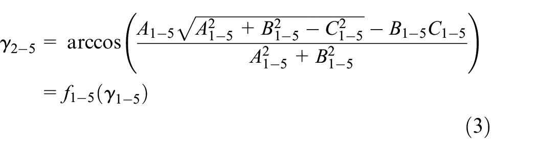


where, γ4-5 is the angle between link E5F5 and G5F5.

In the quadrilateral G5C5B5A5, the coupling relationship between γ5-5 and γ1-5 can be obtained according to the geometric condition shown in Figure 3

where, γ5-5 is the internal angle between link G5C5 and G5A5. α3-5 (α4-5) is the internal angle between link G5C5 (G5A5) and G5D5 (G5F5). Then, the angles in the quadrilateral G5C5B5A5 can be expressed as a function of γ1-5

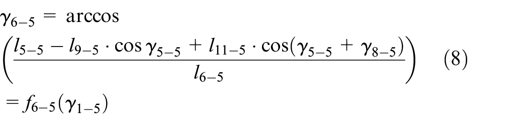

where,

l 5-5 (l9-5, l11-5) is the length of link G5C5 (A5G5, A5B5). γ6-5 (γ8-5, γ7-5) is the internal angle between link G5C5 (A5G5, A5B5) and C5B5 (A5B5, B5C5).
Insert equations (3), (8), and (9) into equation (1), and the unknowns contained in equation (1) are li-5 (i = 1–13), X O C-5 , Y O C-5 , γ1-5, and θ1-5. γ1-5 corresponds to joint angle γs of jumping leg of locust, and θ1-5 corresponds to angle θs of locust. Therefore, insert discrete values of γs and θs shown in Figure 2 into equation (1), and a series of discrete value of center of mass (X(OC-5)k, Y(OC-5)k) (k = 1–8) of the jumping leg can be obtained. (X(OC-5)k, Y(OC-5)k) (k = 1–8) are functions of li-5 (i = 1–13), and the optimization objective function can be expressed as

where, (Xk, Yk) (k = 1–8) is the discrete value of center of mass of the locust, and they are shown in Figure 2.
The link lengths of one DOF jumping leg for configuration 5 can be obtained by optimization algorithm. The optimization results are shown in Table 1. The link lengths of configuration 1-4 can be determined by the same method. The parameters are shown in Figure 4, and the link lengths are also shown in Table 1.
Length of each link for configuration 1-5 [m].

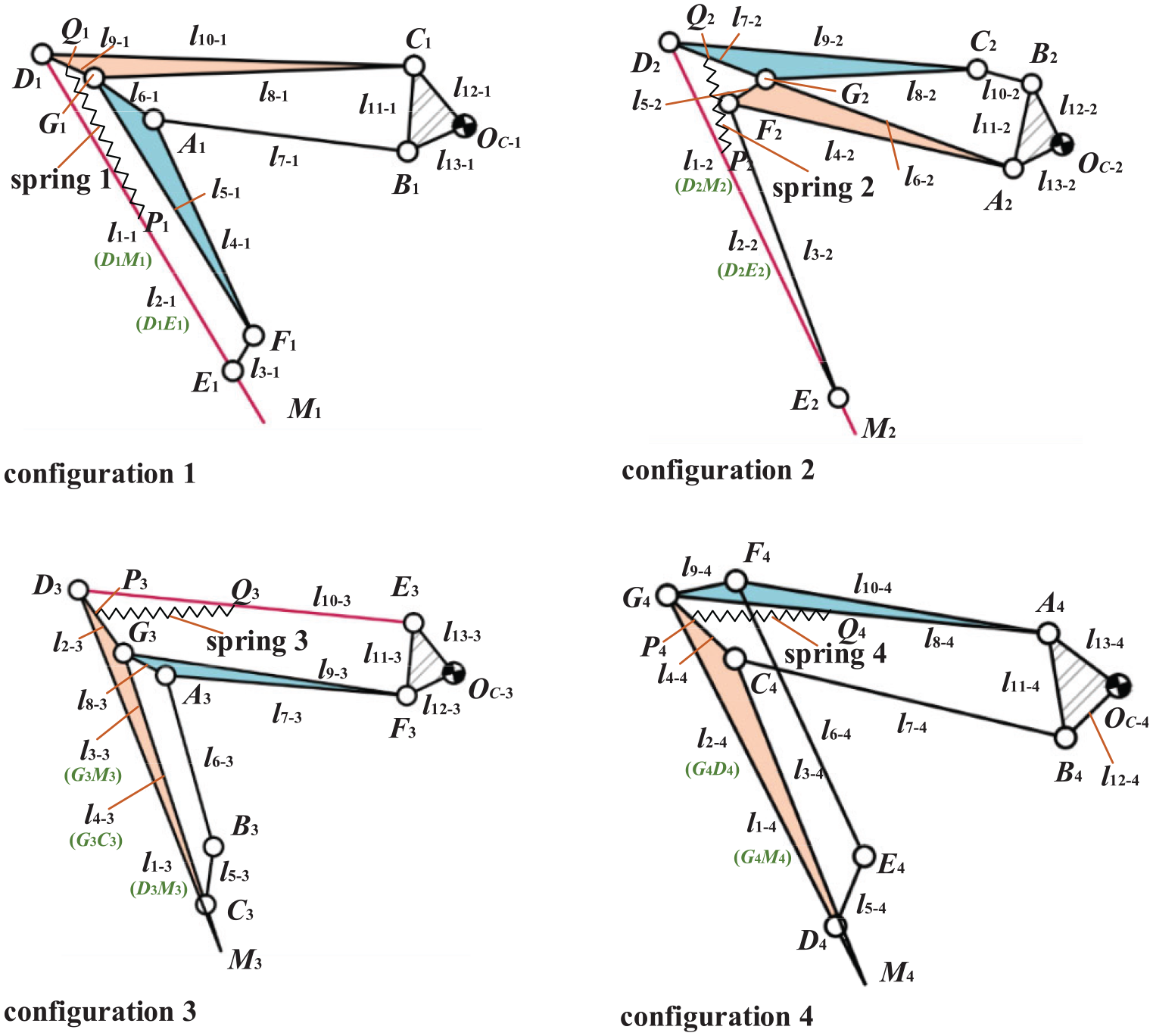
Schematic of configurations 1-4.
Establishment of mathematical model
According to the characteristics of jumping robot, the performance indices can be divided into kinematics indices, dynamics indices and structure indices, and mathematical models are established for analysis.
Kinematic indices
During the take-off process of the robot, take-off direction angle Ψ (the angle between take-off direction line and the horizontal direction, Figure 3) and rotation angle of the trunk θ6 (the angle between the trunk and the horizontal direction, Figure 3) are two important kinematic parameters. Ψ reflects the ability of the robot to overcome obstacles, and θ6 reflects the jumping stability of the robot. The smaller θ6 is, the less likely the robot overturns in the flight phase and the more stable the robot is. 14 θ6 and Ψ can be expressed as


where, li is the length of each link for the jumping leg. K is the stiffness coefficient of the driving spring. (XOC0, YOC0) is the initial coordinate of the center of mass of the robot in the coordinate system M-XMYM. Taking configuration 5 as an example, θ6-5 and Ψ5 can be solved by kinematic analysis.
(1) Take-off direction angle Ψ. The take-off direction angle of the robot is the angle between the resultant external force exerted on the trunk in the initial state and the positive direction of XM axis, which can be shown as
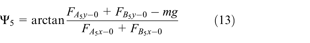
where, m is the mass of robot. (FA5x-0, FA5y-0) and (FB5x-0, FB5y-0) are the forces exerted on the trunk of the robot by the link G5F5A5 and B5C5 in the initial state, respectively. In order to obtain the take-off direction angle Ψ5, the force analysis of the jumping leg in the initial state is conducted. Suppose that the n-th link (n = 1–6) subjects the forces


where, n1 is the number of the force
Insert the initial coordinate(X(OC-5)0, Y(OOC-5)0) (it is known according to experience) of the center of mass of the trunk for the robot in the coordinate system M5-XM5YM5 into equation (1), and all of initial angles of the jumping leg can be obtained according to equations (1)–(9). Then
(2) Rotation angle of the trunk θ6. Since the take-off time of the jumping robot is very short, it can be considered that the center of mass of the trunk moves along the take-off direction line in the take-off process, and the joint angles can be expressed as a function of γ1-5. According to the modeling method shown in section 2 and the geometric relationship shown in Figure 3, the rotation angle of the trunk for the configuration 5 during the take-off process can be expressed as

When γ1-5 is within a given range, the rotation angle of the trunk θ6-5 is related to the length of each link of the jumping leg li-5, the stiffness coefficient of the driving spring K5 and the initial coordinate of the center of mass of the trunk (X(OC-5)0, Y(OC-5)0).
According to the kinematics parameters Ψ and θ6, two kinematics indices are proposed to evaluate jumping performance: sensitivity of take-off direction ΔΨ and change of rotation angle Δθ6. For the former, when the structural parameters change, the robot should keep Ψ without a large change. It means that the structural parameters have little influence on the jumping direction, so that the take-off direction can be accurately controlled when the position of the center of mass cannot determine accurately. For the latter, θ6 should be as small as possible to ensure the jumping stability of the robot. They can be expressed as

where, Ψ0 and
Dynamic indices
The main dynamic parameters of the robot are velocity v, acceleration a, and total inertia moment MI of the trunk in the take-off phase. Dynamic parameters can be written as

Similarly, taking configuration 5 as an example, each dynamic parameter can be solved by following process.
(1) Take-off velocity and acceleration of the trunk. According to the analysis in section 3.1, each joint angle of the jumping leg of configuration 5 can be expressed as a function of γ1-5. Therefore, the angular velocity of each joint can be expressed as a function of γ1-5 and
The Lagrange modeling method is used in this study. The total potential energy of the jumping leg for configuration 5 can be expressed as
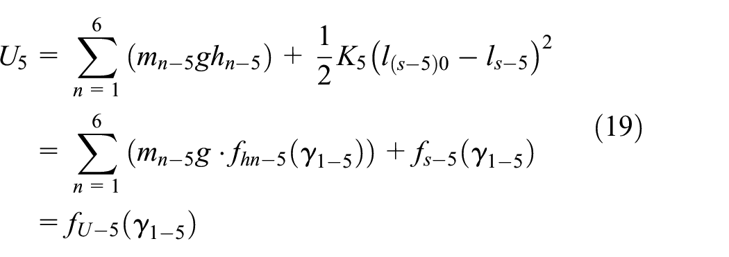
where, mn-5 (n = 1–6) is the mass of each link in configuration 5. hn-5 (n = 1–6) is the height of the center of mass of each link. K5 is the stiffness coefficient of the driving spring. ls-5 is the length of the spring, and l(s-5)0 is the free length of the spring.
The total kinetic energy for configuration 5 can be shown as

where, Jon-5 (n = 1–6) is the moment of inertia of the n-th link of the jumping leg, and it is calculated with respect to the CoM.
Insert equations (19) and (20) into the Lagrange dynamic equation, and the following formula can be obtained.
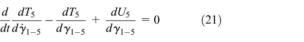
Equation (21) is a second-order quadratic nonlinear differential equation, and the numerical method is used to solve it. Then, the velocity of the trunk can be written as

The acceleration of the trunk can be obtained by derivation of equation (22), and its expression are as follows.

The velocity and acceleration of the robot are both connected to the length of each link of the jumping leg li-5, the stiffness coefficient of the driving spring K5 and the initial coordinate of the center of mass of the trunk (X(OC-5)0, Y(OC-5)0).
(2) Total inertia moment MI. The Newton-Euler method is adopted to solve the joint forces firstly. On the basis of equations (14) and (15), inertial forces

where, ai-5, bi-5, and c5 are elements of matrix, and they are shown in appendix.
According to Ref., 14 the total inertia moment of the robot mainly reflects the dynamic stability of the robot. The smaller the changes in the total inertia moment are, the better the dynamic stability is; that is, the robot has a low tendency to turn over in the flight phase.
According to above dynamic parameters, some dynamic indices are proposed. (a) The resultant velocity (the larger, the better) of the trunk, which reflects the possible velocity loss of the robot in the take-off phase. (b) The fluctuation of acceleration FI. The acceleration curve mainly reflects the change of inertia force of the robot during take-off process. When the acceleration curve fluctuates greatly, the inertial force of the robot fluctuates obviously, which leads to the instability of the robot. Therefore, FI can reflect the motion stability of the robot. (c) The mean of the total inertia moment Ea and variance of the total inertia moment Sa, which reflect the turning trend of the robot in the take-off phase. According to equation (22), the total velocity of the trunk for the robot can be expressed as

For the fluctuation of the acceleration, according to the coordinates of a series of discrete points on the acceleration curve (in the acceleration curve, the x-axis is time and that these points are chosen by considering uniform time steps), a straight line L5 can be obtained adopting fitting method. Then the sum of the distance from all discrete points on the acceleration curve to the straight line L5 is defined as the fluctuation index FI5, that is

where, S5 and K5 are the coefficients of the line L5, and can be obtained by Ordinary Least Squares theory. V5 is take-off time, and W5 is acceleration. (vI-5, wI-5) (I = 1–N) is coordinate of the I-th discrete point in the acceleration curve.
The fluctuation index FI of the acceleration is related to the jumping stability of the robot. The smaller FI, the smoother the acceleration curve is, and the more stable the robot jumps.
The mean value Ea-5 and variance value Sa-5 of the total inertia moment can be expressed as

where, MII-5 is the ordinate of the I-th point on the curve of total inertia moment.
The mean and variance of total inertia moment can reflect the overturn trend of the robot, and they should be as small as possible. 14
Structural index
The structural parameter SI reflects the distribution of the center of mass of the robot. The smaller the SI is, the closer the center of mass of the robot is to the middle position of its structure, and the better jumping performance of the robot is. It can be known form Ref. 14 that the position of CoM of the robot will affect the moment of inertia of the robot, and then affect the rotation angle of the robot in the process of jumping. Therefore, the position of CoM has a great effect on the jumping stability of the robot. Taking the leg attitude at the end of the take-off phase as a reference, SI can be defined as follows

where,

(sn-f, hn-f) (n = 1–6) is the coordinate of the center of mass of the n-th link at the end of take-off process, and it can be obtained by inserting the final joint angles into the expressions of sn and hn.
According to above analysis, performance indices establishment process can be seen in Figure 5. According to different performance parameters, kinematics, dynamics and structure indices are put forward by establishing mathematical models.

Performance indices establishment process. The reference line indicates the distribution of CoM of the locust actually, and SI of the locust can be obtained by equation (28).
Performance comparison for different configurations
In order to analyze the difference of different configurations, the performance comparison is carried out, which provides a reference for the optimal selection of configurations. The object of comparison includes kinematics indices (sensitivity of take-off direction angle and trunk attitude angle), dynamics indices (velocity loss, acceleration fluctuation, and mean and variance of total inertial moment) and structure index (distribution of center of mas).
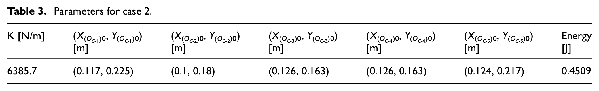
When link lengths are determined, the variable parameters affecting jumping performance include spring stiffness coefficient and initial attitude of the jumping leg (initial position of center of mass). Suppose the energy stored by the mechanism is the same, and two cases are considered. For the case 1, the spring stiffness coefficient is different, and the initial position of the center of mass and the stored energy are constant. The parameters for case 1 are shown in Table 2. For the case 2, the initial position of the center of mass is different, and the spring stiffness coefficient and the stored energy are constant. The parameters for case 2 are shown in Table 3. In particular, the difference in the position of the center of mass reflects the change of the position of the center of mass on the take-off direction line. It is worth noting that since configuration 3 and 4 can be both simplified to four-bar mechanisms, parameters for configurations 3 and 4 are exactly the same in Tables 2 and 3.
(1) Take-off direction angle. The sensitivity of the take-off direction angle should be as low as possible. When the spring connection position and the energy stored by the spring in the initial state remain unchanged, the influence of the change of the position of center of mass on the take-off direction angle is analyzed in this study, because the position of center of mass is difficult for the robot to control accurately. Figure 6(a) and (b) show that the effect of the position of center of mass (that is the coordinate of center of mass in the coordinate system Ot-XtYt, Figure 3) on take-off direction angle for case 1 and case 2, respectively. For the case 1, when the change range of the center of mass is 7 cm, the changes of take-off direction angles for configuration 2 and configuration 5 are only 2.78° and 3.50°, respectively. This shows that when the position of the center of mass cannot be accurately determined, the take-off direction can still be accurately controlled for the robot with these two configurations as jumping leg. For the case 2, the changes of the take-off direction angles for configuration 3 and configuration 4 are both only 0.384°. Figure 6(c) shows the change of take-off direction angle for configuration 3. Two take-off direction lines correspond to the starting and ending points of the curve for configuration 3 in Figure 6(a). The amplitude of the take-off direction angle for different configurations changes greatly due to the change of initial conditions. It is necessary to determine configurations according to actual initial conditions in order to obtain good jumping performance.
(2) Change of trunk attitude. The change of trunk attitude directly reflects the stability of the robot in the take-off phase. Large rotation angle will directly make the robot unstable due to overturn. The change of the attitude angle should be as small as possible. Figure 7(a) and (b) show the changes of trunk attitudes in the take-off phase for two cases. It can be seen from Figure 7 that the rotation angles of the trunk for configuration 2 in two cases are about 30° (rotation angle of trunk of locust does not exceed 10°), which is not conductive to the stability of the robot. The changes of trunk attitudes for configuration 1 in two cases are about 6.45° and 4.10°, respectively. The rotation angle is the smallest of the five configurations. However, the rotation angle of the trunk for configuration 1 increases firstly, and then decreases, which means the trunk turns counter-clockwise first, and then clockwise during the take-off process. Sudden changes in velocity directions may result in poor motion stability. In addition to configuration 1, the rotation angle of trunk for configuration 5 is also very small. The rotation angles are 7.38° and 5.49°, respectively. The changes of rotation angles for configuration 5 are monotonous in two cases, and jumping robot with configuration 5 as jumping leg is easy to maintain jumping stability. To sum up, configuration 5 is a reasonable choice if only trunk rotation is considered.
(3) Change of velocity and acceleration. Figure 8(a) and (b) show the changes of velocities of the center of mass along XM direction and YM direction for case 1, respectively, and Figure 8(c) and (d) show the changes of velocities along XM direction and YM direction for case 2, respectively. For case 1, the maximum velocities of the robot with configuration 1 or 5 as jumping leg are large, and the velocities for configuration 1 fluctuate obviously. In particular, for both cases, the amplitudes of velocities for configuration 2 decrease significantly. Figure 8(e) shows the maximum sum velocities for different configurations, and the results are consistent with the above analysis. The reason why the maximum velocities for configuration 2 under two cases decrease greatly is that its angular velocity is very large, and most of the energy is rotational kinetic energy. This is consistent with the analysis results shown in Figure 7(a) and (b). For the jumping robot, when the stored energy is equal, it is necessary to ensure that it has large velocities along XM direction and YM direction, and the change trend is gentle. It means that the angular velocity of the robot is as small as possible in the take-off phase. Therefore, configurations 1 and 5 meet the above requirements.
Parameters for case 1.

Parameters for case 2.

Relationship between the position of center of mass and the take-off direction: (a) ensuring the same energy by changing the spring stiffness coefficient, (b) ensuring the same energy by changing the initial position of the center of mass, and (c) change of take-off direction for configuration 3.

Change of trunk attitude in the take-off phase for different cases: (a) change of trunk attitude for case 1 and (b) change of trunk attitude for case 2.
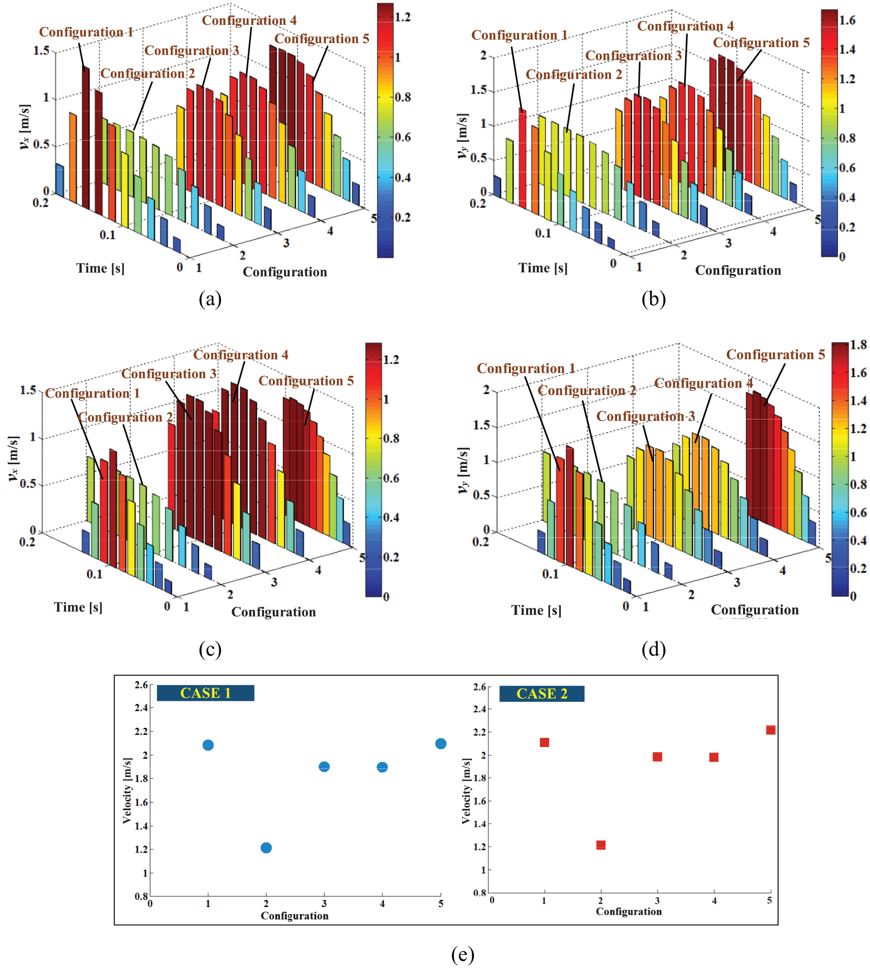
Changes of velocities along XM axis and YM axis for two cases and maximum total velocity: (a) changes of velocities along XM axis for case 1, (b) changes of velocities along YM axis for case 1, (c) changes of velocities along XM axis for case 2, (d) changes of velocities along YM axis for case 2, and (e) changes of maximum total velocities for two cases.
The fluctuation index FI of the acceleration is also related to the jumping stability of the robot. Figure 9(a) and (b) show initial accelerations and fluctuation indices for five configurations in case 1 and 2, respectively. Since the initial accelerations for five configurations are all larger than zero, robot with any configuration as jumping leg can take off normally. For case 1, the fluctuations of accelerations for configuration 1 along XM axis and for configuration 2 along YM axis are obvious, and the fluctuation indices are 0.89 and 0.58, respectively. In contrast, the fluctuations of accelerations for configuration 5 along XM axis and YM axis are very small, and this is good for the robot to maintain good jumping stability. The changes of accelerations for configuration 1 and 5 in case 1 can be seen in Figure 9(c). For case 2, the fluctuations of accelerations for configuration 1 along XM and YM axis are largest, while fluctuation indices for configuration 5 along XM and YM axis are smallest. The changes of accelerations for configuration 1 and 5 in case 2 are shown in Figure 9(d). In particular, although the fluctuations of accelerations for configuration 3 and 4 along XM axis and YM axis are small and close to those of configuration 5, the rotation angles of the trunk for configuration 3 and 4 are not small (Figure 7), which is not good for the jumping stability of the robot. In summary, the fluctuations of accelerations for configuration 1 and 2 are large, and the fluctuation of acceleration for configuration 5 is small. This is consistent with the change trend shown in Figure 7.
(4) Change of total inertia moment. Figure 10(a) and (b) show the changes of mean and variance of total inertia moment for case 1 and case 2, respectively. For case 1, the absolute values of mean of total inertia moment for configuration 1 and 2 are large, and they are 0.56 Nm and 0.53 Nm, respectively. The mean of total inertia moment for configuration 3-5 are relatively small, with little difference in magnitude. In addition, the variance of total inertia moment for configuration 2 is the largest, and the variance for other configurations are small. Therefore, for case 1, the robots with configuration 1 or 2 as jumping leg may have poor jumping stability. This is consistent with Figures 7(a) and 9(a). The changes of total inertia moments for five configurations in case 1 can be seen in Figure 10(c), and “zero planet” means the horizontal plane crossing zero point. For case 2, the change trend of mean and variance of total inertia moment is basically similar to that in case 1. The only difference is that the mean for configuration 5 is slightly larger than that of configuration 3 and 4. The changes of total inertia moments for five configurations in case 2 can be seen in Figure 10(d). Besides, although the mean and variance of total inertia moment for configuration 3 and 4 are very small in case 2, it can be seen from Figures 7(b) and 9(b) that the rotation angles of the trunk and the fluctuations of accelerations for configurations 3 and 4 are not small, so the stability of the robot with configurations 3 or 4 as jumping leg is not good.
(5) Distribution of center of mass. The structural index SI can reflect whether the center of mass of the robot is located at the middle position of its structure. From the analysis in section 3.3, the smaller SI is, the better performance of the robot is. Figure 11 shows the distribution of center of mass for five configurations. The horizontal line represents the distribution of center of mass of the locust, and SI = 0.179. It can be seen from Figure 11 that the structural index SI for configuration 1 is largest, and SI for configuration 2 is smallest. So the center of mass for configuration 1 is farthest away from the middle position of its structure. Non-uniformity of mass distribution will make the robot tip over during the jumping process.

Changes of accelerations for five configurations: (a) changes of initial accelerations and fluctuation indices for case 1, (b) changes of initial accelerations and fluctuation indices for case 2, (c) changes of accelerations corresponding to configurations with the maximum FI and minimum FI in case 1, and (d) change of accelerations corresponding to configurations with the maximum FI and minimum FI in case 2.

Changes of total inertia moment of five configurations: (a) changes of mean and variance of total inertia moment for case 1, (b) changes of mean and variance of total inertia moment for case 2, (c) changes of total inertia moment of five configurations in case 1, and (d) changes of total inertia moment for five configurations in case 2.

Distribution of center of mass of the robot with different configurations.
It can be seen from the above analysis results that there is no one configuration that is best or worst for any performance indices. For example, the robot with configuration 5 as jumping leg may have good jumping stability, while the sensitivity of take-off direction angle is low in case 2, and the take-off direction cannot be accurately controlled. Therefore, the comprehensive evaluation of performance should be conducted to obtain the rank of these five configurations.
Comprehensive evaluation of performance
In the comprehensive evaluation of jumping performance of the robot, it is necessary to consider the effects of kinematic, dynamic and structural indices above mentioned on the jumping performance of the robot comprehensively. However, there are too many indices, and the degree of correlation among different indices is different. The correlation of some indices is very significant, which makes it possible for the information provided by them to overlap. Therefore, on the basis of analyzing the single jumping performance index for different configurations, principal component analysis (PCA) method is adopted to evaluate the jumping performance of the robot comprehensively. The PCA method can be used to simplify the data structure by replacing the original multi-dimensional variables with a few comprehensive variables while minimizing the loss of original data information.32,33 In this study, the PCA method is mainly used to rank the jumping performance of the jumping legs with different configurations, which can provide guidance for the optimal selection of jumping legs. The process of the principal component analysis can be divided into the following steps.
(a) Standardization of index data. It is necessary to transform the indexes with different measurement units and different dimensions into standardized data for further evaluation. Suppose that n indexes of m different configurations constitute the index data matrix.

The matrix

where,
From equations (29) and (30), the standardized matrix can be obtained
where,
(b) Determination of correlation coefficients matrix

where,
(c) Calculation of eigenvalues and eigenvectors of matrix

After that, according to equation

where,
(d) Determination of the number of principal components. The number of principal components reflecting the jumping performance of robots is determined by the cumulative variance contribution rate of performance indexes, that is the proportion of variance to total variance

When
(e) Determination of expressions of principal components


From the analysis in section 3, there are 10 indexes reflecting the jumping performance in total, and they are shown in Table 4.
The ten indexes reflecting the jumping performance.

These 10 indexes can be divided into three categories: positive indexes, reverse indexes and moderate indexes. The larger the value of positive index is, the better jumping performance of the robot will be, the smaller the value of reverse index is, the better jumping performance of the robot will be, and the closer the value of the moderate index is to a value t, the better jumping performance of the robot will be. In the comprehensive evaluation, the indexes should be assimilated with the same trend. Generally, the reverse indexes and moderate indexes can be transformed into positive indexes, and the formula can be shown as

where, t is the best value of the index.
After assimilating the index with the same trend, the index data matrixes
The index data matrixes of case 1 and 2.

Then the index data matrix is standardized, and the corresponding correlation coefficient matrixes
Eigenvalues and contribution rates in case 1 and 2.

It can be seen from Table 6 that the cumulative contribution rates of the first and second components in case 1 and 2 can be expresses as

Therefore, the number of principle components are both two in case 1 and case 2. According to equation (37), comprehensive evaluation function of case 1 and 2 can be written as
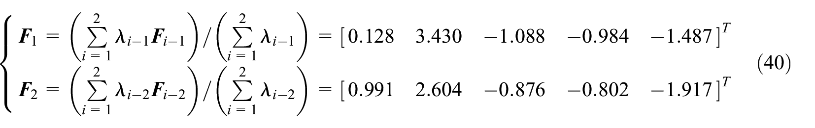
According to equation (40) and Ref., 38 the ranks of the comprehensive jumping performance for the five configurations can be seen in Figure 12. For case 1 and case 2, the comprehensive jumping performance for five configurations is ranked as 2>1>4>3>5, and the comprehensive performance of configuration 3 and 4 is similar. Although the jumping stability of the robot with configuration 2 is not the best according to the analysis in section 4, the comprehensive jumping performance of configuration 2 is the best after comprehensive consideration of several indices. For configuration 5, although its jumping stability is good, the comprehensive performance of configuration 5 is poor.

Ranks of jumping performance for five configurations: (a) ranks of jumping performance for five configurations in case 1 and (b) ranks of jumping performance for five configurations in case 2.
In particular, if some of the eight indices have no significant effect on the jumping performance of the robot (that is the indices are not necessary to be considered), the ranks of the comprehensive jumping performance for five configurations will be different from that shown in Figure 12. For example, if the distribution of center of mass for the five configurations is the same, and the positions of the center of mass are all located at the middle position of the structure, the index SI is not necessary to be considered. At this time, the ranks of the comprehensive performance of the configurations are shown in Figure 13. The ranks of the comprehensive jumping performance in case 1 and case 2 are 5>3>4>1>2 and 4>3>5>2>1, respectively. For case 1, it is better to choose configuration 5 instead of configuration 2, while for case 2, it is better to choose configuration 4 rather than configuration 1.

Ranks of jumping performance for five configurations when some indices are not considered: (a) ranks of jumping performance for five configurations in case 1 and (b) ranks of jumping performance for five configurations in case 2.
Conclusion
One DOF six-bar mechanism has the advantages of various configurations and abundant motion laws, and has broad application prospects in bioinspired mechanisms. In order to solve the optimal selection problem of six-bar mechanisms with different configurations, a method of modeling, evaluation and optimal selection for bionic six-bar jumping legs was proposed in this study. The innovative work of this study includes: (a) Based on the motion parameters of locust’s jumping leg, a method for determining the link length was proposed, which makes the one DOF six-bar jumping leg approximately reproduce the motion law of locust, and ensures that all configurations are compared with same standard. (b) Based on the established mathematical models, the evaluation indices for jumping performance were put forward, which include kinematics indices (sensitivity of take-off direction angle and trunk attitude angle), dynamics indices (velocity loss, acceleration fluctuation, and mean and variance of total inertial moment) and structure index (distribution of center of mas). (c) A configuration optimal selection method based on principal component analysis was proposed, and configurations can be clearly selected although the performance for different indices is different for one configuration. The above research provides a useful reference for the design, modeling and optimal selection of one DOF bioinspired mechanisms.
Future studies could include optimizing all parameters of the jumping leg simultaneously and experimental study of bioinspired jumping robot. Then the jumping performance of robot in complex terrain in three-dimensional space needs further modeling and analysis.
Footnotes
Appendix
For equation (16)
where,
For equation (19)
where, ls1-5 is the length of E5P5, and ls2-5 is the length of E5Q5. l14-5 is the distance from the hinge D5 to the center of mass of link D5C5G5, and l15-5 is the distance from the hinge G5 to the center of mass of link G5F5A5.
For equation (20)
where, c5 and d5 are the length and width of the trunk of the robot respectively.
For equation (24)
where, aix-5 and aiy-5 (i = 1∼6) are the acceleration of the center of mass of the i-th link along the XM and YM axis respectively.
Handling Editor: James Baldwin
Declaration of conflicting interests
The author(s) declared no potential conflicts of interest with respect to the research, authorship, and/or publication of this article.
Funding
The author(s) disclosed receipt of the following financial support for the research, authorship, and/or publication of this article: This work was supported by the National Natural Science Foundation of China (Grant No. 51805010), General Project of Beijing Education Commission (Grant No. KM201910005032), and China Postdoctoral Science Foundation funded project (Grant No. 2019T120030).