
Abstract
With the increase of the engine intensified degree, mechanical load and thermal load become to the two main factors limiting the engine to intensify. Application of Miller cycle, which can be realized by late intake valve closing (LIVC) and deeper late intake valve closing (DLIVC), has the potential to reduce the effective CR, mechanical load, and thermal load. In this paper, the effects of LIVC and DLIVC on the mechanical load and thermal load of a boosted DI diesel are experimentally compared. Compared to the original base case, the average cylinder temperature of LIVC and DLIVC is reduced by 90 and 52 K. The exhaust temperature of LIVC and DLIVC decreased by 26 and 14 K, and the maximum combustion pressure of LIVC and DLIVC decreased by 1.6 and 9.7 bar. The pumping losses of LIVC and DLIVC are reduced by more than 25%, while the actual cycle power does not decrease due to the late closing of the inlet valve. The fuel consumption rate decreased from 250.1 g/kWh of base case to 240 g/kWh of LIVC, reduced by 4.0%. The indicated thermal efficiency increased from 41.9% of base case to 43.7% and 42.5% of LIVC and DLIVC. Miller loss is only 2.55% with Miller inlet phase.
Introduction
Facing increasingly stringent emission and fuel consumption regulations, vehicle engines are experiencing a new technological revolution under the guidance of the concept of Downsize. The essence of this concept is to replace the large displacement engine with the small displacement engine by enhancing the power density and keeping the power performance unchanged. The core of Downsize technology is how to organize fast and efficient combustion process and improve engine power density.1–10 The high efficiency combustion system (HECS) diesel engine prototype developed by FEV Engine Consulting Co., Ltd. in Germany11–13 uses a single-stage VGT turbocharger with a boost ratio of 3.8, the injection pressure is 200 MPa, the maximum pressure in cylinder is controlled at 20 MPa, and the power density reaches 105 kW/L at the speed of 4800 r/min. On this basis, the power optimization is carried out, and the HECS-P combustion system is developed, and the power density reaches 115 kW/L. The French IFP Institute14,15 obtained a power density of 90 kW/L under the maximum pressure in cylinder less than 20 MPa, and the excess air coefficient can be reduced to 1.18 under the smoke FSN ≤ 3.0 limit, which greatly improves the quality of fuel and gas mixing. The research were studied on a single cylinder machine with common rail injection pressure of 200 and 250 MPa, the results show that increasing the injection pressure is more conducive to the rapid mixing and efficient combustion of fuel and gas than reducing the nozzle diameter, and higher power density can be obtained. Volkswagen 16 has been carrying out research on working fluid flow in cylinder, fuel spray characteristics, and rapid mixing of fuel and gas for many years, and its research results are applied to product development. In 2015, a Passat 2.0 LTDI diesel engine was developed for Euro VI emission. Its power density has reached 88 kW/L and rated speed is 4000 r/min. The high pressure common rail fuel system with injection pressure of 250 MPa, the high boost ratio and the low boost ratio are 1.5 and 3.8, respectively. The maximum pressure in cylinder is controlled within 18 MPa. Due to the high cycle intake and fuel injection volume, the instantaneous heat release rate and cumulative heat release are very high, and the heat flux density is large, resulting in mechanical load and heat load problems, which has become one of the important bottlenecks restricting the development of high-strength diesel engines.
Miller cycle has been widely concerned and studied because of its ability to reduce thermal load and fuel consumption.17–28 Miller cycle forms high expansion ratio and low compression ratio working cycle through early or late closing of intake valve, which has obvious effect on reducing combustion pressure and temperature in cylinder. Nevin et al. 29 studied the effect of the closing phase of the intake valve on the performance of a four-valve direct injection single-cylinder diesel engine. It was found that under the premise of maintaining a certain intake pressure, with the delay of the closing phase of the intake valve, the pressure and temperature in the cylinder decreased significantly when the piston was located at the top dead center. Millo et al. 30 took a simulation study on a two-stage turbocharged heavy-duty diesel engine. It was found that the combustion temperature and pressure were suppressed after the Miller cycle, so that the engine power can be further strengthened. Under the premise of maintaining the same maximum combustion pressure, the performance calculation results show that the engine power has about 5% improvement potential and the fuel consumption has also improved to some extent. Kovacs et al. 31 systematically expounded the improvement potential of performance and emission of heavy-duty diesel engine after applying Miller cycle, and conducted Miller cycle test on a medium-load high-pressure common rail diesel engine. The results showed that the emission of the engine was significantly improved after applying Miller cycle. At the same time, a decrease in the maximum combustion pressure can increase power by about 10%.
The above research on the influence of Miller cycle on combustion and performance of diesel engine has been very extensive, but these studies mainly focus on reducing NOx emissions and improving thermal efficiency under low and medium speed and partial load conditions. The research on the influence of Miller intake phase on combustion and gas exchange process of high-strength diesel engine under high speed and heavy load conditions is still rare. This paper further studies the inhibition of excessive mechanical load and heat load, and the improvement of thermal efficiency of diesel engine under certain mechanical load.
Experimental equipment and methods
The test was carried out on a high strength single cylinder diesel engine. The main structural parameters are shown in Table 1. The single cylinder machine is specially designed for the study of high intensity combustion process. The maximum explosion pressure can reach 25 MPa and the maximum speed can reach 4500 r/min. The layout of high-strength single cylinder test system is shown in Figure 1. It can be seen from the diagram that during the intake process, the air is first compressed by an air compressor, and then enters the single cylinder machine test room through a regulator box with a cooling device to form a simulated pressurization system. In the single cylinder test room, compressed air enters the cylinder after passing through the second stage regulator. Both inlet temperature and inlet pressure can be adjusted and feedback controlled according to the set values. As shown in Figure 1, the intake flow is measured by the laminar air flow meter installed behind the first stage pressure regulator. The transient pressure of the intake pipe and the exhaust pipe is measured by two piezoresistive pressure sensors installed on the intake pipe and the exhaust pipe. The high pressure common rail fuel system is driven by an additional motor alone. The solenoid valve injector is vertically arranged in the center of the combustion chamber, and the rail pressure is set to 180 MPa. The fuel consumption is measured by the fuel consumption meter installed between the fuel tank and the high pressure fuel pump. The test adopts the 6052 type cylinder pressure sensor produced by Swiss Kistler Company, and the maximum measurement pressure is 25 MPa. The self-made cylinder pressure acquisition and combustion process analysis system collects the cylinder pressure data of 100 cycles under each working condition, and the data are averaged and smoothed. The sampling frequency of the combustion analyzer is 0.5°CA. According to the measured cylinder pressure, the combustion process parameters can be calculated by using the first law of thermodynamics.
Engine main parameters.

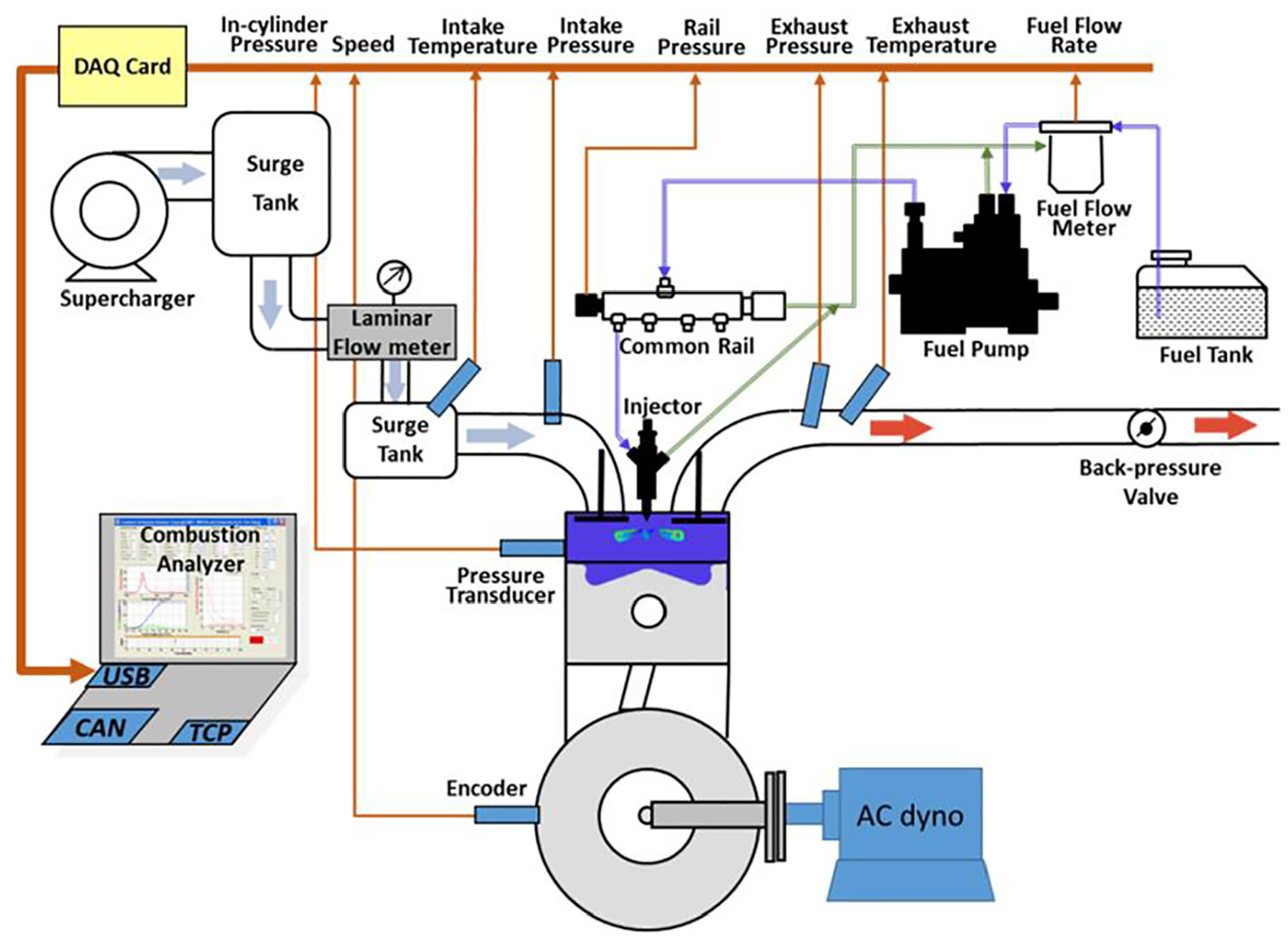
Boosted diesel engine test system.
The single cylinder machine adopts intake and exhaust double top camshaft valve mechanism. The intake valve lift curve is shown in Figure 2. The valve has a clearance of 0.5 mm and the actual valve lift is 8 mm. The exhaust valve phase remains unchanged during the test. By replacing the intake camshaft of the Pi contour line, the Miller intake phase is realized by delaying the IVC phase while keeping the intake opening phase unchanged. The original IVC phase is 70°CA after BDC, and the other two Miller intake phases are 110°CA and 120°CA after BDC, respectively, marked as Base cam, LIVC cam, and DLIVC cam.
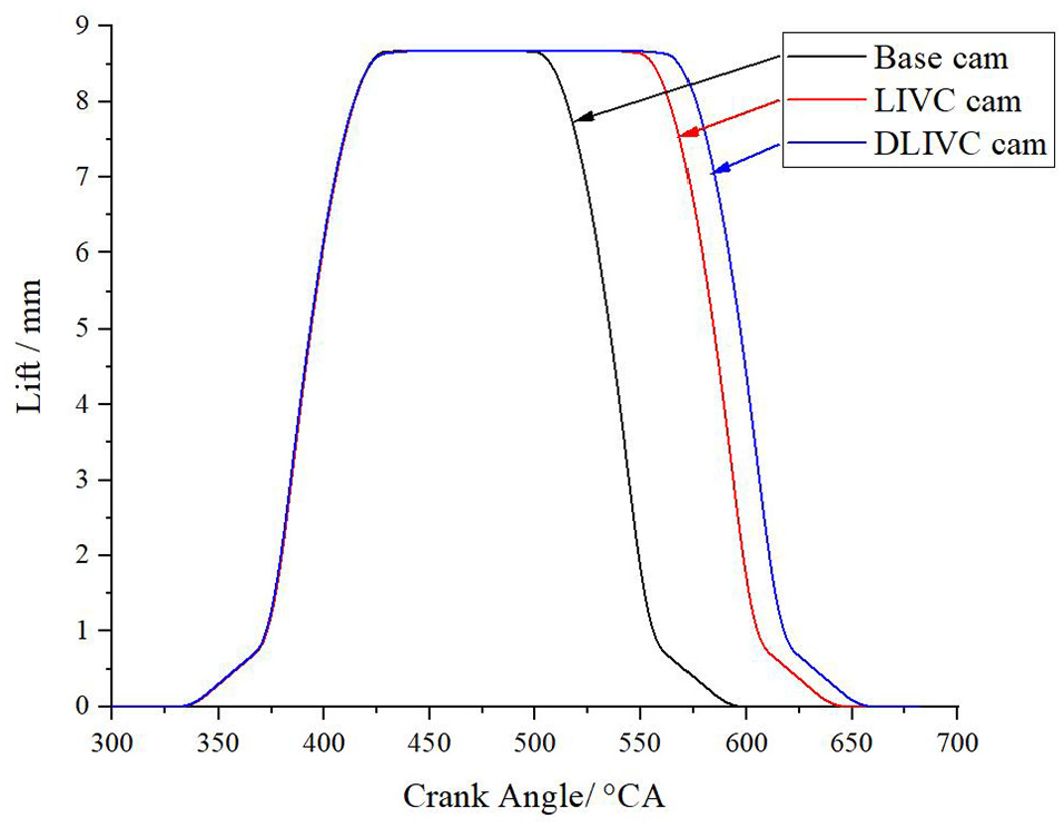
Valve lift profiles for different camshafts.
In order to explore the effect of Miller cycle on combustion and gas exchange process of high strength diesel engine, the experiment was carried out at the speed of 3800 r/min and the average effective pressure was 26 bar. In order to keep the output power unchanged, the injection pressure was fixed at 180 MPa, and the excess air coefficient was maintained at around 1.7 by adjusting the inlet pressure to compensate for the change of air intake caused by Miller phase. At this phase, the injection pulse width and the injection advanced angle were adjusted.
Results and analysis
Effects of LIVC and DLIVC on Miller loss
The compression process of the ideal cycle of the internal combustion engine is an adiabatic compression process. However, due to the late closing of the inlet valve, the compression curve will deviate from the adiabatic process and form the compression loss. In the Miller cycle with late closing of the intake valve, the compression loss caused by the significant delay in the compression starting point cannot be ignored. The deviation between the actual compression line from the stop point to the IVC phase and the adiabatic compression line reaching the same cylinder pressure is defined as Miller loss, which can be calculated according to the following formula (1).

Where,
Figure 3 below shows the pressure-volume (P-V) curves at the initial stage of compression at different IVC phases. The three dashed lines in the Figure 3 are the ideal adiabatic compression lines of cylinder pressure at different IVC phases. It is obvious from the diagram that with the delay of IVC phase, the gap between the actual cylinder pressure line and the ideal adiabatic compression line is increasing, that is, the Miller loss increases.

P-V curves at different IVC timings during initial compression.
The Miller loss work and its proportion to the cycle indicator work calculated according to the cylinder pressure indicator diagram measured by the experiment are shown in Figure 4. It can be seen from the diagram that the Miller loss power increases with the delay of the IVC phase, and the proportion of Miller loss power relative to the indicator power increases as the cyclic indicator power remains unchanged in this experiment. When the case of Base is 70°CA before the termination point, Miller’s lost power is 0.19% of the cycle indicator power. When the case of DLIVC is delayed to 120°CA before the termination point, Miller‘s lost power is 12.7 times of the cycle indicator power, 2.55% of the cycle indicator power.

Miller loss work and its percentage over the indicated cycle work.
Effects of LIVC and DLIVC on gas exchange process
After the intake valve late shut Miller cycle, due to the early part of the compression has entered the cylinder fresh charge is pushed back to the intake system, resulting in intake charge loss. Figure 5 shows the influence of inlet pressure on Miller phase. In order to keep the output power unchanged, it is necessary to increase the intake pressure to maintain the fresh charge in the cylinder. When the IVC phase is postponed from the case of base (70°CA) to 110°CA (the case of LIVC), the intake pressure increases by 51.1 kPa, 10.7%, and when the phase is postponed to 120°CA (the case of DLIVC), the intake pressure increases by 82.1 kPa, 17.1%.

Effect of miller cycle on the inlet pressure.
For the average pump pressure, when the inlet pressure is greater than the average exhaust pressure, the average pump pressure is positive, when the inlet pressure is less than the average exhaust pressure, the average pump pressure is negative. Figure 6 shows the influence of Miller cycle on pumping loss. It can be seen from the figure that the average pump gas pressure under the original machine phase is negative, the pumping loss is large, and the pump gas power is negative 0.08 MPa. With the delay of IVC phase, the intake pressure increases and the average pump pressure increases, but it is still negative 0.02 MPa. This indicates that the Miller inlet phase is beneficial to increase the average pump pressure.
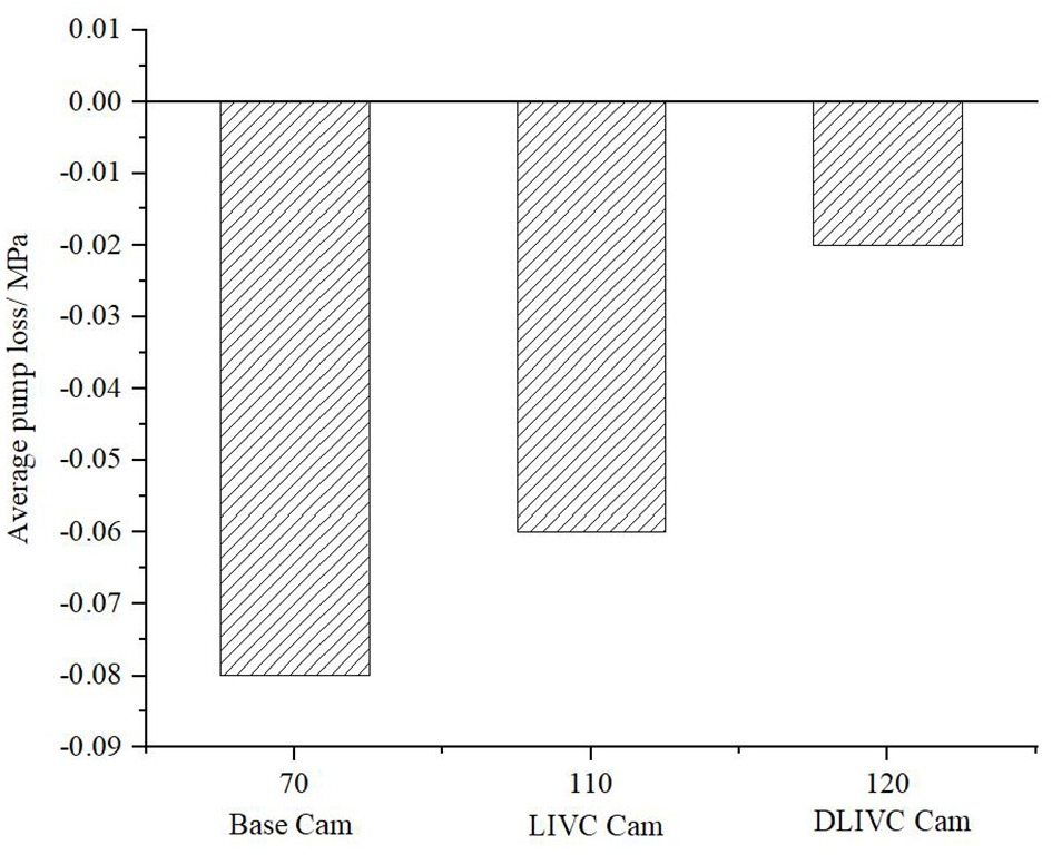
Effect of miller cycle on the mean effective pumping pressure.
Figure 7 shows the variation of in-cylinder charge coefficient at different IVC phases. From the diagram, it can be seen that with the delay of IVC phase, the charge coefficient decreases, from 88.8% of the case of base cam to 77.3% of the case of LIVC, and to 71.5% of the case of DLIVC. This is mainly due to the increase of intake reflux with the delay of IVC phase.

Effect of miller cycle on the charging coefficients.
Effects of LIVC and DLIVC on combustion temperature
According to the measured cylinder pressure curve, the variation of the average temperature of the working substance in the cylinder is calculated with the help of the ideal gas state equation, so as to examine the heat load level of the engine. Figure 8 shows the variation of average temperature in cylinder with crankshaft angle at different IVC phases. It can be seen from the figure that with the delay of IVC phase, the average temperature of working substance in the cylinder decreases significantly, which is mainly due to the decrease of effective compression ratio. At the beginning of injection 18°CA, the average cylinder temperature of the case of LIVC (110°CA) is 90 K lower than that of the case of Base (70°CA). With the combustion process going on, the difference of the average cylinder temperature between the two reaches 52 K at the compression TDC. The maximum combustion temperature appears at 30°CA after the TDC, and the difference of the maximum combustion temperature between the two is about 109 K. The average cylinder temperature of the case of DLIVC (120°CA) is lower than that of the case of Base (70°CA).
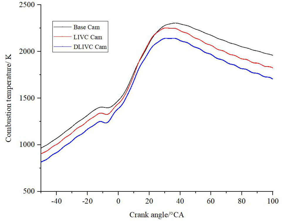
Effect of miller cycle on the mean cylinder temperatures.
Figure 9 shows the variation of exhaust temperature at different IVC phase. It can be seen from the figure that Miller cycle reduces the exhaust temperature to a certain extent. The exhaust temperature of the case of LIVC at 110°CA is 11 K lower than that of the original machine at the case of Base at 70°CA, and the exhaust temperature of the case of DLIVC at 120°CA is 14 K lower than that of the original machine at the case of Base at 70°CA, which load of the exhaust system.

Effect of miller cycle on the exhaust temperatures.
Effects of LIVC and DLIVC on combustion pressure
Figure 10 shows the high pressure P-V diagram at 3800 rpm and 2.6 MPa BMEP. It can be seen from the figure that under the same excess air coefficient, the maximum combustion pressure has been reduced to a certain extent after using the Miller cycle with the late closing of the intake valve. The maximum combustion pressure of the case of LIVC at 110°CA is 1.6 bar lower than that of the case of Base at 70°CA, and the maximum combustion pressure of the case of DLIVC at 120°CA is 9.7 bar lower than that of the case of Base at 70°CA. Overall, due to the downward movement of the compression line and the expansion line, that is, the compression pressure and the combustion pressure decrease, and the pump loss decreases, the actual cycle power does not decrease due to the late closing of the intake valve, that is, the power output does not decrease after the Miller cycle, and the output power of the combustion process of the three intake valve closing phases is similar.

Effect of miller cycle on the pressure in cylinder.
Effects of LIVC and DLIVC on heat release characteristics
Figure 11 shows the test results of indicating fuel consumption rate and indicating thermal efficiency at different IVC phases. It can be seen from the figure that under the premise of a certain excess air coefficient, with the delay of IVC phase, the fuel consumption rate is indicated to decrease from 250.1 g/kWh of the case of Base (70°CA) to 240 g/kWh of the case of LIVC (110°CA), which is reduced by 4.0%. This is because the pump loss is reduced after the Miller phase is first adopted. On the other hand, the compression pressure line is significantly reduced and the expansion pressure line is reduced less after the Miller phase, resulting in an increase in the work of the high pressure cycle. In addition, the decrease in the exhaust temperature also reduces the exhaust heat loss of the whole cycle. The 120°CA intake phase (the case of DLIVC) indicates that the fuel consumption rate is reduced by 3.1 g/kWh, which is less than that of the former. The main reason is that there is a large backflow in the intake under this intake phase. Accordingly, the indicated thermal efficiency increased by 2.8% and 1.4% respectively from 41.9% of the case of Base at 70°CA to 43.7% and 42.5% of the case of LIVC and DLIVC at 110°CA and 120°CA.

Effect of miller cycle on the BSFC and thermal efficiency.
The crankshaft angle corresponding to the cumulative heat release rate of 5% is defined as the combustion starting point, and the crankshaft angle corresponding to the cumulative heat release rate of 90% is defined as the combustion end point. The crankshaft angle corresponding to the combustion starting point to the combustion end point is the combustion duration, and the crankshaft angle corresponding to the cumulative heat release rate of 50% is the combustion center. Figure 12 shows the effect of Miller cycle on main combustion period and combustion phasing. The ignition delay period refers to the crankshaft angle from the start of fuel injection to the start of fire. With the delay of the intake valve phase closing angle, the main combustion duration gradually decreases, from 57.5°CA in the case of Base (70°CA) to 54.9°CA in the case of LIVC (110°CA) and 52.3°CA in the case of DLIVC (120°CA). The main reason is that after Miller cycle, the maximum combustion pressure decreases under the same excess air coefficient. In order to maximize the effect of Miller cycle, the injection advance angle is appropriately advanced by 1°CA, and the corresponding advance of the gravity of combustion center leads to the decrease of the combustion duration. Figure 13 shows the effect of Miller cycle on ignition delay period. With the delay of the intake valve phase closing angle, the ignition delay period gradually decreases, from 16.9°CA in the case of Base (70°CA) to 16.7°CA in the case of LIVC (110°CA) and 15°CA in the case of DLIVC (120°CA), the miller cycle shortens the ignition delay.

Effect of miller cycle on the main combustion period and combustion phasing.
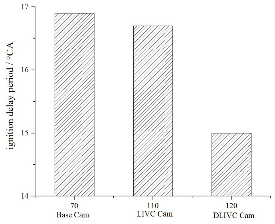
Effect of miller cycle on ignition delay period.
Figure 14 shows the changes of instantaneous heat release rate and cumulative heat release rate at different IVC phase. It can be seen from the figure that after the Miller intake phase is adopted, the rising line of the instantaneous heat release rate of combustion does not change much with the IVC phase. This is mainly because the power density at this operating point is high, and the pressure, temperature, and density at the end of the cylinder compression are high enough. The change of the working substance state in the cylinder caused by the Miller intake phase is not sufficient to cause significant changes in the ignition delay, spray characteristics, and fuel-gas mixing characteristics. However, the peak value of instantaneous heat release rate increases with the delay of IVC phase, and the corresponding crankshaft angle that reaches the same cumulative heat release is advanced. This is mainly because the injection advance angle of Miller phase is advanced by 1°CA, resulting in a rapid increase in the instantaneous heat release rate at the early stage of the main combustion period, and a rapid decrease in the instantaneous heat release rate at the late stage of the main combustion period. In addition, the fuel and gas at the late stage of injection lacks the effect of high-speed spray characteristics, which corresponds to the decrease of temperature and pressure in the cylinder at the late stage of diffusion combustion.
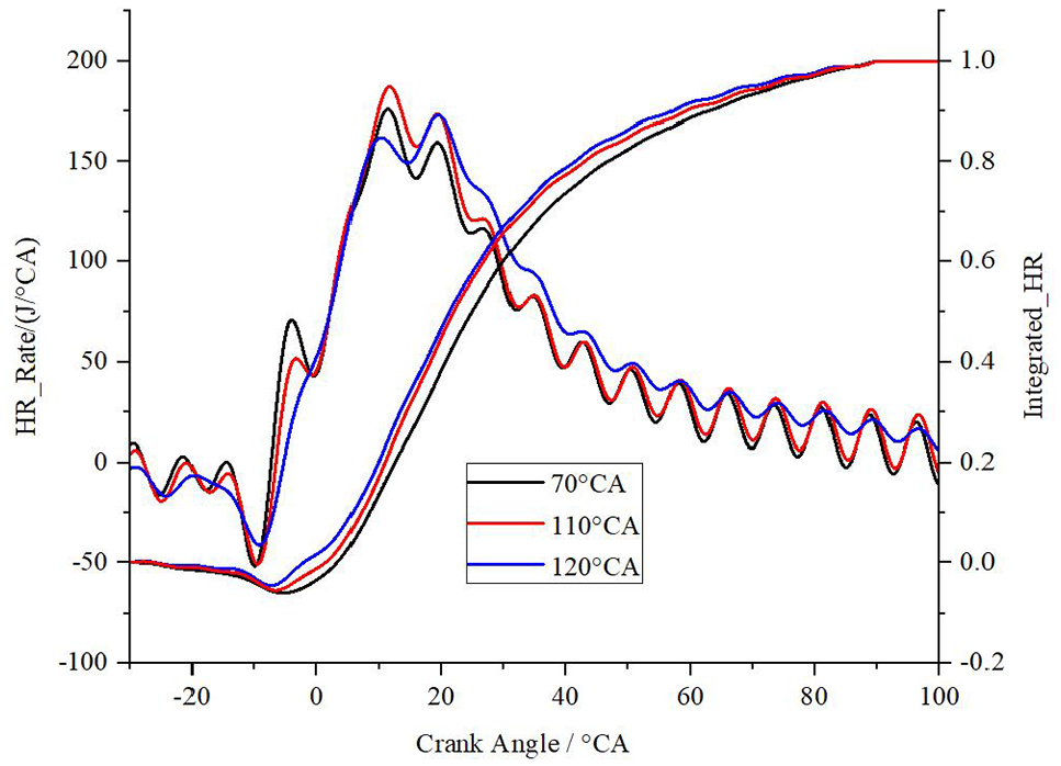
Effect of miller cycle on the cumulative and instantaneous heat release rate.
Conclusions
With the delay of IVC phase, the charge coefficient decreases, which is mainly caused by the increase of inlet backflow with the delay of IVC phase. Correspondingly, in order to keep the output power unchanged, it is necessary to increase the intake pressure to maintain the fresh charge in the cylinder. At the same time, the pumping loss is greatly reduced, indicating that the Miller inlet phase is beneficial to reduce the pumping loss.
With the delay of IVC phase, the average temperature of the working substance in the cylinder decreases significantly, mainly due to the decrease of the effective compression ratio. Miller cycle reduces the exhaust temperature to some extent, which has a certain effect on reducing the heat load of the exhaust system.
Under the same excess air coefficient, the maximum combustion pressure has been reduced to a certain extent after the Miller cycle with the late closing of the inlet valve is adopted. On the whole, due to the downward movement of the compression line and expansion line, namely, the compression pressure and combustion pressure decrease, and the pumping loss decreases, the actual cycle work does not decrease due to the late closing of the inlet valve.
Under the premise of a certain excess air coefficient, with the delay of IVC phase, the indicated fuel consumption rate decreased significantly, the indicated thermal efficiency increased to a certain extent, and the main combustion duration gradually decreased.
Footnotes
Handling Editor: Chenhui Liang
Declaration of conflicting interests
The author(s) declared no potential conflicts of interest with respect to the research, authorship, and/or publication of this article.
Funding
The author(s) disclosed receipt of the following financial support for the research, authorship, and/or publication of this article: Shanxi High-level Talent Team Project, Research Institutes Stable Support Funding Project, financial support from the National Natural Science Foundation of China (No. 51476151) is gratefully acknowledged.