
Abstract
The instability of the thermally grown oxide is the fundamental source leading to failure relevant to spallation and delamination of top coat. A finite element model is developed to understand failure mechanism of thermal barrier coating systems. Lateral and normal growth strains are stimulated by ABAQUS field variable expansion. Our results show that the valley region of top coat/thermally grown oxide interface and the peak region of thermally grown oxide/bond coat interface are the initiation locations of cracks. The creep can suppress downward displacement at the valley and promote the upward displacement at the periphery. Large material creep induced by further enhanced residual stress can restrain the increasing trend of the tensile stress within top coat and contribute to changes of thermally grown oxide morphology. Conversely, the applied load can promote the downward displacement at the valley and suppress the upward displacement at the periphery. The larger mechanical loads enhance the displacement rate toward bond coat layer, implying that the larger extension rate of thermally grown oxide instability accelerates the coating failure.
Keywords
Introduction
Thermal barrier coating systems (TBCs) are widely used to improve performance of the engine. The cost of the research of thermal barrier coating technology is much lower than that of development of new superalloy, and the process is feasible. A typical current TBC system consists of four layers: a ceramic top coat (TC) for improving the ability of thermal shock resistance; a bond coat (BC) layer is deposited between the TC and superalloy substrate, with the main function to ease the thermal expansion mismatch; a very thin thermally grown oxide (TGO) layer forms between the BC and TC during high-temperature exposure. The degradation of TBCs is an extremely complicated process including external factors and internal factors due to complex work condition. Observed macroscopic spallation of the ceramic layer mainly results from crack initiation and propagation,1–4 in which case, a broad range of residual stresses are responsible for cracking. The stresses mainly include the following aspects: TGO thermal growth stress, phase transformation stress, and the thermal stress due to thermal expansion mismatch.5–10 However, the TBCs is subjected to thermal cycles and mechanical loads because the turbine blades rotate at a high speed in air with high pressure and temperature. The mechanical loads which influence the coating lifetime play critically important role. Experimental investigations have affirmed that the TGO instability is subjected to thermal cycling is a key factor for interface cracking.1–4,10–13 TGO undergoes large residual compressive stress due to TGO growth and thermal expansion misfit. With the in-plane stress accumulating upon thermal cycling, TGO instability displaces down at the valley and upward at its periphery.7,13 The TGO instability introduces intense stresses into the superposed TC, which motivates cracks within TC. 12 Tensile and compressive stresses occur above the valley and at the periphery of the imperfection, respectively. The strains generated by the TGO instability are basic to the TBCs. 2 Additionally, the strains caused by thermal expansion misfit and TGO growth are superimposed. The plastic strains and microcracks within TC, however, can lead to stress relaxation. Stress relaxation due to material creep and plastic deformation resulting from material yield generally reduces stress level, especially at high temperature. Meanwhile, the plastic deformation and microcracks would, in turn, promote the extension of TGO instability on a cycle-by-cycle basis. The phenomenon can give rise to enhanced stress accumulation after thermal cycling, further motivating early crack at TBC/TGO and TGO/BC interfaces.10,14
The physical mechanism of the TGO growth is that oxygen reacts with Al cations at the BC interface regions between TC and BC interfaces.2,8 Extensive research results have shown a broad range of factors including TGO growth, material creep and mechanical loads contribute to extension of TGO instability; hence, it would shorten the service life of TBCs.7,15–17 However, the effects of TGO instability associated with material creep and mechanical loads on the extension of TGO instability have not been globally and adequately researched. With regard to the recent works, using different interface morphologies, Ranjbar-far et al. 10 explored the crack propagation model on the TC/TGO and TGO/BC interfaces and the effects of crack propagation. The work shows crack propagation depends on interface morphology and on thickness of the TGO layer. Using finite element method (FEM), Su et al. 13 studied effect of TGO creep on TC cracking, comparing results under different TGO creep rates; they found creep behavior restrains the local distortion of the instability zone, which can significantly reduce the shear stress levels around the periphery of the instability. However, none of these previous studies considered the effect of mechanical loads on extension of TGO instability.
The TGO instability under a variety of mechanical loads, thermal and thermomechanical loading regimes results in important regions of stress concentration in the interfacial zone.9,10,18 These local stress zones may give rise to the crack initiation and propagation at TBC/TGO and TGO/BC interfaces further causing the coating spallation. Such phenomenon could be more prominent because the applied mechanical loads may promote the extension of TGO instability, which could, in turn, accelerate the failure of the TBCs. So in this work, before embarking on assessments of the effects of material creep and mechanical loads, failure mechanism is investigated based on TGO growth associated with material creep. Possible damage scenarios resulting from crack initiation and propagation are inferred. Then, we will analyze the effects of material creep and mechanical loads on the extension of TGO instability. The variations of residual stress and displacement rates upon thermal cycling are investigated in the process of TGO instability extension. Possible reasons triggering the phenomenon are presented to gain information about the critical factors which are favorable for TGO instability extension. TGO growth is simulated by imposing the desired strains. Simulation of TGO growth denoted by anisotropic swelling is conducted by the ABAQUS field variables expansion. 19 The results of this work contribute to fully figuring out effects of the combined effects of material creep and mechanical loads on failure of TBCs.
The finite element model
Geometric model and boundary conditions
In this work, a corresponding generalized plane strain model is implemented to address the issue. Figure 1 displays the simplified model which consists of the substrate (2000 µm), BC (80 µm), TGO (3 µm), and TC (150 µm). 13 Based on the prior experimental observations of TGO instability morphology, the imperfection is simplified to be a periodic array. 7 The imperfection of the interface regions between TC and BC is idealized as a sinusoidal geometry with a typical undulation amplitude of 15 µm and a wavelength L of 60 µm, as shown in Figure 1, 10 where L is the width of the imperfection zone. The previous numerical investigations have shown the width W of the distance of each periodic array set to W = 3L gives rise to highest crack extension rate, 12 therefore we adopt W = 3L. Analysis of a cycle unit cell is made owning to periodic boundary imposed. The symmetrical boundary condition is applied at the left side, meanwhile periodic boundary condition is imposed on the right side using multi-point constraint (MPC) 19 which forces the nodes on the boundary to move simultaneously in the horizontal direction but leaves nodes unconstrained in other directions. Before executing simulation, the temperature of the mode is set to 1100°C, and TBCs are assumed to be stress-free due to the fact that coating process is achieved at high temperature; then thermal cycling is exerted, which consists of 600 s of cooling from peak temperature to ambient temperature, 600 s of reheating from ambient temperature to 1100°C, and 30-min holding stage at a peak temperature of 1100°C. Meanwhile, mechanical loads of 1.2 and 2.4 MPa are applied at the holding stage, whereas the mechanical loads vary linearly from 0 to peak value at reheating stage and from peak value to 0 at cooling stage, respectively. The direction of compressive load is perpendicular to the interface of TC.

The synopsis of the finite model.
Material properties
TGO, TC, substrate are treated viscous–elastic while taking into account the elastic and viscous–plastic behavior of BC. Material properties which are referred to the literatures20–24 are listed in Table 1. All the materials are considered temperature-dependent for a realistic numerical simulation. Nevertheless, creep behavior is evident when material experiences high stress and high temperature. For creep behavior of each layer, the following Norton power law creep behavior is adopted

where
Summary of material parameters.

Creep parameters of each layer.

TGO behavior
For TBCs is subjected to cyclic high temperature, the TGO thickness increases due to the oxidation of the BC layer. As observed in experiments, the TGO thickness evolution is as follows 26

where
In the FEM model, the lateral growth and normal growth of TGO is simulated by applying the desired growth strain at high temperature. The strains caused by formation of new oxide incorporate two components:

Results and analysis
Stress distribution along the TBC/TGO and TGO/BC interfaces
The major weakness of TBCs is located at the interface between TC and BC within the TBC. Accompanying with high stresses present at TC/TGO and TGO/BC interfaces, TGO morphology changes in service. The tensile stress (σ22) distribution where the stress are relevant to occurrence of interface cracking are obtained. σ22 mainly results in the lateral cracks which are fatal to coatings because it would cause spallation of TC afterward within TBCs. Accordingly, normal stress at TC/TGO and TGO/BC interfaces for both cases that the system undergoes no TGO growth (N = 0 cycle) and BC oxidation (N = 24 cycles) are emphatically analyzed. As shown in Figure 2(a), imperfection zone of TC/TGO interface is under compression after cooling. The zone adjacent to the imperfection and at a low tensile stress further away. Nevertheless, in the case of TGO growth, compared with stress magnitude in the case without TGO growth, the stress magnitude is significantly increased in the case of TGO growth. The maximum tensile stress occurs at the valley of TC/TGO interface, while compressive stress is present at the peak of the imperfection, suggesting possible locations for cracks to initiate and develop at the valley. When the cracks located at the valley of TC/TGO propagate toward the peak, we can predicate the crack propagations at the TC/TGO interface would be restrained around the compressive region near the peak. As can be found in Figure 2(b), it displays an opposite stress distribution feather at the TGO/BC interface. For both cases with and without TGO growth, the maximum tensile and compressive stresses always arise, respectively, at the peak and valley of the TGO/BC interface, which agrees well with the preceding result. 10 Notably, the zone under compression extends from valley to flank region, and its stress level is sufficiently high. We predict the existing cracks at the peak of the TGO/BC interface are able to extend, whereas the crack propagations have to be stopped when they propagate into compressive zone situated in at the flank of TGO/BC interface. However, the phenomenon is temporary because subsequent heating and cooling can change the stress state. As a result, the crack extension is motivated, leading to subsequent coalescence of interfacial cracks. Nevertheless, the experimental evidences of Padture et al. 28 and Busso and Qian 17 have revealed the valley region of TC/TGO interface, and the peak region of TGO/BC interface are the initiation locations for interface cracking. Comparisons of the numerical results above with experimental observation reveal reasonable consistency. It has been postulated that the interface strength approximately equals to that of the material having the lower mechanical resistance, namely, interface strength is set to the ceramic at the TBC/TGO interface and BC for TGO/BC interface, respectively. The yield strength of ceramic varies from 10 to 100 MPa,20,22,23 and for BC layer, it fluctuates within a range of 215–270 MPa.20,23 As illustrated in Figure 2, the largest tensile traction is found at the valley of TC/TGO interface and at the peak of TGO/BC interface. Accordingly, we predicate the failure modes of TBCs is due to the spallation of TC layer for its lower interface strength, which agrees well with the general view of failure mechanism of TBCs.

Tensile stress along the interfaces after cooling when the systems experience 0 and 24 cycles: (a) TC/TGO interface and (b) TGO/BC interface.
The extension of TGO instability
The numerical results are obtained for the various cases with different combinations of mechanical compressive stress and creep considerations. The combined effects of material creep and mechanical loads on the evolution of tensile stress at the critical regions are analyzed. Further understanding is gained by inspecting TGO deformation which can display the evolution of TGO instability morphology. When the extension is up to a certain extent, spallation and delamination of TC would occur, thus to some extent characterizing the coating failure.
The variation of displacement rates
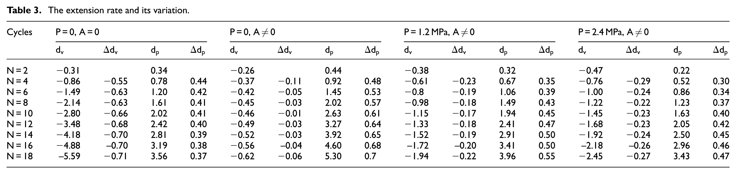
The displacement rate is analyzed because it can characterize the extension rate of TGO instability, which to some extent influences the service life of the coating. Displacements at the valley and at the periphery are denoted as
The extension rate and its variation.
The effect of material creep
To explore the effect of the material creep on the extension of TGO instability, Figures 3 and 4 present the TGO deformation for the cases that the system undergoes no creep (A = 0) and the system is assigned real creep property (A ≠ 0), respectively. It exhibits that downward displacement occurs at the valley of the imperfection, while upward displacement trend (pile-up) is present around the periphery. The finite element simulations for the displacement instability of TGO are compared to the TGO instability morphology observed in the scanning electron microscope (SEM). As shown in Figure 5, 27 the TGO instability displaces downward at the center and upward around the periphery. This prediction from FEM closely matches the experimental observation demonstrating the power of the proposed model to accurately predict the extension of TGO instability. However, the displacement feature reveals significantly different in Figures 3 and 4. When the system undergoes creep deformation, the downward displacement tends to decrease. The upward displacement is more prominent than that in the case without creep, which is in reasonable agreement with the result obtained by Su et al. 13 The same element near the TC/TGO interface at the valley of the TGO instability is selected to observe tensile stress variation upon thermal cycling to further elaborate the effect of TGO growth associated with creep on failure of the TBCs. Apart from little difference in stress magnitude, the stress variations for the cases (P = 0 MPa, P = 1.2 MPa, and P = 2.4 MPa) resemble each other, so the evolution of tensile stress for the case (P = 0, A ≠ 0) upon thermal cycling is investigated. We focus on the variation of stress amplitude because spallation failure is relevant to the stress magnitude. So it would not lead to fundamental errors when it is postulated that the stress varies lineally. The stress variation in a cycle is described above. As shown in Figure 6, the compressive stress switches to tensile stress due to the TGO growth. TGO growth leads to stress increasing rapidly during the dwell time, and the tensile stress increases in magnitude as the thermal cycles. The magnitude of tensile stress increases significantly at the initial cycles, whereas the tensile stress becomes almost invariant in magnitudes at the subsequent cycles, indicative of a cyclic steady state. The stress is at a low level in the first few thermal cycles. As the thermal cycles proceed, residual stress accumulates to a certain extent; consequently, the effect of material creep on stress becomes obvious. Stress relaxation due to creep is responsible for the result that the increasing trend of tensile stress is restrained upon thermal cycling. The thermal barrier coating in service, however, is required to experience the sequence of cooling, reheating, and holding. In this process, as can be seen obviously in Figure 6, temperature circulation induces thermal stress cycle, which gives rise to the fatigue phenomenon. Thermal fatigue promotes gradual extensions of microcracks as thermal cycles proceeds, resulting in coating spallation related to thermal fatigue damage. We now discuss the effect of displacement on variation of tensile stress. Downward displacement at the valley of the imperfection is the source of tensile stress. The small downward displacement means small tensile stress. It manifests in the contrast between displacement variations of multiple thermal cycles in Table 3 that the increasing trend of displacement at the valley is restrained as thermal cycles. The displacement feather is observed to mutually agree with the tensile stress evolution characteristic mentioned above that the increasing trend of tensile stress magnitude is suppressed upon thermal cycling.

The TGO displacement contours during dwell time for A = 0 (without creep) and P = 0: (a) 2 cycles, (b) 10 cycles, and (c) 18 cycles.
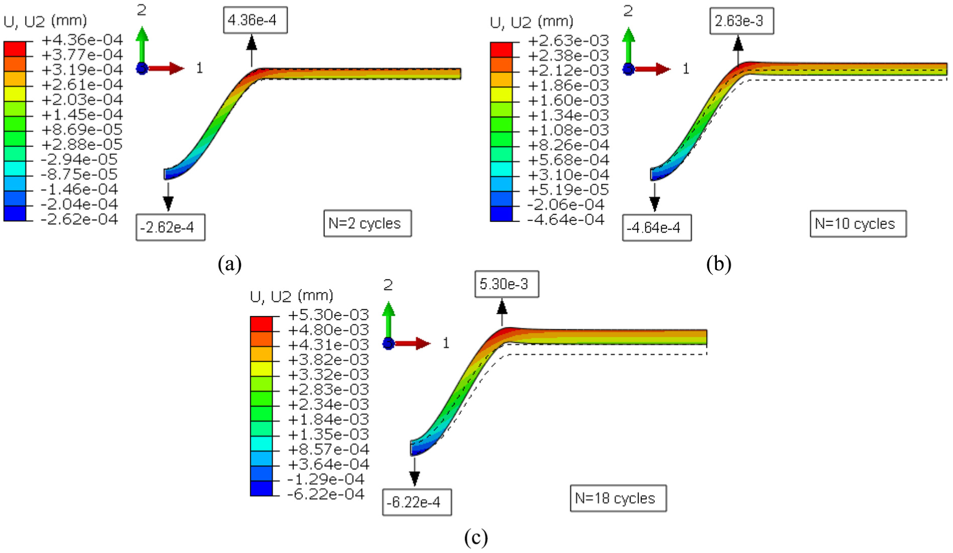
The TGO displacement contours during dwell time for A ≠ 0 (with creep) and P = 0: (a) 2 cycles, (b) 10 cycles, and (c) 18 cycles.
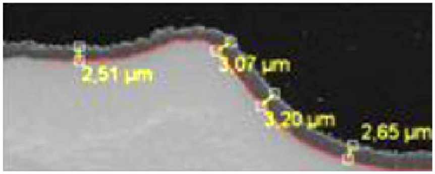
The TGO instability morphology observed in the SEM.

Evolution of the tensile stress with the thermal cycles.
The effect of mechanical loads
Figures 7 and 8 show TGO deformation with applied compressive stress. We now discuss cases in which the system is applied with compressive stress. Numerical simulations are conducted for compressive stresses of 0, 1.2, and 2.4 MPa; considerable differences among the TGO deformations of several typical cycles are observed, thereby showing the dependence on the level of mechanical loads. As also can be noted in Table 3, the downward displacement at the valley increases, while the upward displacement at the periphery is diminished as the compressive stress grows from 0 to 2.4 MPa. The valley of instability displaced downward and the periphery of the instability flattens gradually to accommodate the significant extension of TGO instability toward the BC layer. So the morphology of TGO can be easily influenced by the magnitude of the applied tensile stress. Because the region at the TC/TGO interface is favorable for crack nucleation and propagation, an element near the TC/TGO interface at the valley of the TGO instability is selected to observe tensile stress variation versus elapsed time. Due to the similarity in stress variation of each cycle, without loss of generality, the evolution of tensile stress at the fifth cycle is studied. As shown in Figure 9, after cooling, the tensile stress is decreased due to thermal misfit. The tensile stress decreased significantly and moved toward a value of approximately zero during the reheating stage. At holding time, tensile stress increases rapidly due to TGO growth. The lateral growth at holding stage results in rapid downward displacement at the valley. The increase in the downward displacement will directly enhance the tensile stress above the valley of the imperfection, which is consistent with the stress results shown in Figure 2(a). Simultaneously, the increased material creep tends to relax such a stress state to a steady state. As the applied stress increases, the tensile stress level would be reduced. Notably, the compressive stress at the periphery is increased due to the applied mechanical loads. TGO instability preferentially displaced into BC when there is lower tensile stress at the valley and higher compressive stress at the periphery. However, the mechanical loads are high enough when TBCs is in service condition, which can significantly diminish the tensile stress at the valley and enhance compressive stress at its periphery. Consequently, the extension of TGO instability is promoted. The phenomenon agrees very well with the result above that the applied load can promote extension of TGO instability toward BC layer. Once the mechanical loads are removed, the tensile stress becomes large enough, and spallation and delamination would occur at the valley.

The TGO displacement contours during dwell time for A ≠ 0 (with creep) and P = 1.2 MPa: (a) 2 cycles, (b) 10 cycles, and (c) 18 cycles.

The TGO displacement contours during dwell time for A ≠ 0 (with creep) and P = 2.4 MPa: (a) 2 cycles, (b) 10 cycles, and (c) 18 cycles.

Variation of the tensile stress for a typical cycle.
Conclusion
In this study, a periodically symmetry model has been performed with the consideration of geometry imperfection, thermal misfit, and creep behavior of materials. During the thermal cycles, the TGO growth at high temperature has been emphasized. The effects of cyclic TGO instability on distribution of residual stress at the critical regions have been numerically researched. In view of TBCs experiencing high mechanical loads in service, the combined effects of material creep and mechanical loads on the extension of TGO instability have been investigated to facilitate understanding of TBCs failure. The major conclusions are summarized as follows:
Compared with stress magnitude in the case without TGO growth, the stress magnitude is significantly increased in the case of TGO growth. We predicate that the microcracks initiate preferentially at the valley of TBC/TGO interface and at the peak of TGO/BC. Nevertheless, delamination and spallation preferentially occur in TC layer due to lower interface strength, which is major failure mode of TBCs.
Material creep induced by further residual stress accumulation at the subsequent several cycles is evident, which can suppress TGO displacement at the valley. Downward displacement is suppressed. Accordingly, the increasing trend of the tensile stress is restrained upon thermal cycling. We can conclude that TGO growth leads to enhanced residual stress accumulation, while material creep results in stress relaxation.
The creep can suppress downward displacement at the valley and promote the upward displacement at the periphery. Conversely, the applied load can promote the downward displacement at the valley and suppress the upward displacement at the periphery, implying that the mechanical loads would drive extension of TGO instability toward the BC layer.
The mechanical loads enhance the downward displacement rate at the valley and reduce the upward displacement rate at the periphery. So the mechanical loads would accelerate coating failure.
Footnotes
Handling Editor: Crinela Pislaru
Declaration of conflicting interests
The author(s) declared no potential conflicts of interest with respect to the research, authorship, and/or publication of this article.
Funding
The author(s) disclosed receipt of the following financial support for the research, authorship, and/or publication of this article: The authors gratefully acknowledge the support for this work from National Nature Science Fund of China (51405391 and 51402238), Fundamental Research Foundation (JC201138) at Northwestern Polytechnical University, Aeronautical Science Foundation of China (2012ZD53053).