This study investigates the vibration power flow behavior and performance of inerter-based vibration isolators mounted on finite and infinite flexible beam structures. Two configurations of vibration isolators with spring, damper, and inerter as well as different rigidities of finite and infinite foundation structures are considered. Both the time-averaged power flow transmission and the force transmissibility are studied and used as indices to evaluate the isolation performance. Comparisons are made between the two proposed configurations of inerter-based isolators and the conventional spring-damper isolators to show potential performance benefits of including inerter for effective vibration isolation. It is shown that by configuring the inerter, spring, and damper in parallel in the isolator, anti-peaks are introduced in the time-averaged transmitted power and force transmissibility at specific frequencies such that the vibration transmission to the foundation can be greatly suppressed. When the inerter is connected in series with a spring-damper unit and then in-parallel with a spring, considerable improvement in vibration isolation can be achieved near the original peak frequency while maintaining good high-frequency isolation performance. The study provides better understanding of the effects of adding inerters to vibration isolators mounted on a flexible foundation, and benefits enhanced designs of inerter-based vibration suppression systems.
There have been consistent interests in developing high-performance vibration isolation systems for applications to engineering systems and scientific equipment,1–3 for example, for gravitational wave detection.4 Passive vibration isolators have been extensively used to mitigate the transmission of excessive vibration from a source to a receiving structure.5 The design methodology of a conventional spring-damper isolator has been well-documented.1 For a single degree-of-freedom (SDOF) vibration isolation system with natural frequency , effective isolation of force transmission can be achieved when the excitation frequency is larger than . Consequently, there is usually a trade-off between having a low static deflection of the spring and a low natural frequency. The use of conventional isolator for low-frequency excitations is therefore constrained. In view of this, there is much recent interest in exploiting nonlinearity to achieve high-performance vibration isolators.6 For example, by configuring a negative stiffness mechanism to a conventional isolator, it is possible to achieve a low natural frequency for large frequency band of effective vibration isolation while maintaining a high static supporting stiffness.7
Much work has been reported on the use of a recently proposed passive device, the inerter, to enhance the effectiveness of vibration suppression systems. The inerter is a two-terminal passive mechanical element, which has the property that the force applied is proportional to the relative acceleration between the terminals, that is, , where b is the named inertance and and are the acceleration of two terminals.8 This element can be used to provide inertial coupling to modify the dynamic behavior of the integrated system. Since the introduction of the inerter concept, its applications to vehicle suspension systems,9 to aircraft landing gear shimmy suppression,10 to the vibration suppression of cables,11 as well as to building vibration control system12,13 have been investigated and enhanced vibration mitigation performance has been successfully demonstrated. A recent study shows that using inerters can lead to better damping performance of dynamic systems for a higher energy dissipation efficiency.14 It was also shown that the attachment of inerter-based suppression device to laminated composite plates can reduce the vibration level of the structure over a wide frequency range.15 In terms of vibration isolation, the potential benefits of using inerters have been demonstrated by detailed dynamic analysis and performance evaluation of the SDOF and dual-stage linear inerter-based vibration isolators,16,17 harmonically forced oscillators coupled via an inerter-based joint,18,19 and continuous metamaterial beam structures with embedded inerter-based devices.20 By exploiting the geometric nonlinearities of a pair of oblique inerters, a nonlinear inertance mechanism can be generated and nonlinear inerter-based isolators can be created for better isolation performance.21 An enhanced energy conversion device with a tuned inerter was also studied experimentally to show potential performance benefits.22
For performance evaluation of vibration isolators, the force transmissibility, which is defined as the ratio of the amplitude of the force transmitted through the isolator to the foundation and that of the excitation force, has been often used as an index.23 Time-averaged vibration power flow, which combines the effects of force and velocity amplitudes as well as their relative phase angle in one quantity can be used to better reflect the vibration energy transmission within a dynamical system.24–26 Vibration power flow analysis (PFA) method is a widely accepted tool to characterize the dynamic behavior of coupled systems and complex structures. Various PFA approaches, such as a dynamic stiffness method,27 a receptance method,28 a mobility method,29 energy flow models based on finite element,30 a substructure method,31 a progressive approach,32 and a power flow formulation based on continuum mechanics33 have been developed to investigate linear vibration control systems. Mobility and damping based power flow mode theories have also be proposed to facilitate the application of power flow design and control approaches to dynamic systems.34,35 In recent years, the PFA methods have also been developed to examine the power flow behavior of nonlinear dynamical systems, including the Duffing oscillator,36 nonlinear vibration isolators,37 and dynamic vibration absorbers.38
Previous studies have focused on the performance evaluation of inerter-based vibration isolators mounted on rigid foundations.16,17,21,39 However, in many build-up structures such as ships and civil buildings, the base structures on which machines are installed via vibration isolators are relatively flexible. Due to the flexibility, the vibration energy is transmitted through the isolator into the foundation structure to cause undesirable vibration and structural-borne sound. It is therefore important to consider the flexibility of the foundation structure in the design of inerter-based vibration isolators. Also, limited number of previous studies on inerter-based vibration suppression systems have used vibration power flow as an index to access the effectiveness of vibration attenuation. To achieve high-performance vibration isolation, it is also necessary to examine the influence of the flexibility of finite and infinite foundations and different ways of configuring inerter, spring, and damper in the isolators on the vibration energy transmission within the integrated system.
This study attempts to address the issues by investigating the vibration power flow characteristics of different inerter-based isolators installed on finite or infinite beam-like foundation with different flexibility. The aim of using inerters in the isolator is mainly to minimize the energy transmitted from the machine into the base structure. To find the effects of the using inerters as well as the influence of having a flexible foundation, force transmissibility, and time-averaged vibration power flow are obtained and used as indices for performance evaluation. The remaining content is organized as follows. In Section 2, the physical model of the system including the inerter-based isolators and analytical derivations of the steady-state responses are presented. In Section 3, both force transmissibility and the time-averaged vibration power flow are formulated for the current isolators. In Section 4, the performance of the two configurations of the proposed isolators mounted on finite or infinite foundation of varying flexibility is analyzed. Performance comparisons of the isolators are also carried out. Conclusions are drawn in at the end of the paper.
Mathematical modeling
Model description
Figure 1(a) provides a schematic diagram of the integrated system comprising a mass, an inerter-based isolator, and a foundation structure. The mass m represents a vibrating rigid machine, which is subject to a harmonic force excitation of complex amplitude and frequency ω, that is, . To suppress the vibration transmission from the machine to the foundation structure, an inerter-based vibration isolator is inserted between the mass and mounting point B. In the steady state, the mass and point B are assumed to be oscillating with complex amplitude and with frequency , respectively.
(a) An inerter-based vibration isolation system with flexible foundation structure, (b) inerter-based vibration isolator configuration C1, and (c) inerter-based vibration isolator configuration C2.
It is noted that there can be two ways of installing the machine on the foundation structure. One is for the force-excited mass to be rigidly mounted on the foundation without any vibration isolator in between. Another option is to insert a vibration isolator between the machine and the foundation. In both situations, vibration can be transmitted to the foundation structure. The aim of using a vibration isolator is to reduce the level of vibration transmission to the foundation. In this paper, the use of the inerter-based isolators with different configurations is investigated for performance benefits. The action mechanism of the inerter in vibration isolators lies in the fact that the device can store kinetic energy and hence provide inertial coupling between different DOFs, such that the dynamic properties can be tailored for favorable characteristics suppressing the transmission of vibration.
In built-up structures such as buildings and ships, a machine is usually mounted through the isolator on a flexible foundation. The mobility frequency-response function (FRF) has been widely used as an index to characterize the dynamics of engineer structures. For the foundation structure shown in Figure 1(a), its mobility function at the mounting point B is the ratio of the complex amplitude of the velocity and that of corresponding transmitted force:
where denotes the complex amplitude of the transmitted force at point B, , represents the complex amplitude of the displacement of the mounting point such that the corresponding velocity amplitude is expressed by . Note that when the foundation structure is a simply supported uniform beam with bending stiffness , cross section area A, length , and density , we have24
where is point mobility function at B for a finite beam structure, (with j = 1, 2, 3, …) denotes the natural frequencies of the beam, represents the mass normalized mode shape with as the total mass of the beam, is the damping factor to the mode j, and is the longitudinal position of the mounting point.
In applications such as the structural vibration control systems of buildings,24,40 the foundation structure may behave as an infinite structure, it has been shown that the mobility function of an infinite beam is expressed by24
where stands for the mobility function of an infinite beam. To simplify the expression, this equation can be rearranged to have
where and denote the module and phase angle, respectively, is a positive constant and is a real constant in the range of .26 Therefore, the point mobility of a foundation exhibiting infinite structure characteristics can be represented by:
By introducing , the mobility function in equation (5) can be rewritten as
where denotes the mobility function of a generalized infinite structure. Hence, large values of and indicate a very flexible foundation, while small values of them represent a rigid foundation.
Figure 2 provides a comparison of the magnitude of the mobility function for finite and infinite beam structure with variations of the excitation frequency. The parameters of the beam are set as , . The solid, dashed-dotted, and dotted lines are for mobility functions expressed by equations (2), (3) and (6), respectively. The solid line represents a finite foundation with the length m. The dashed-dotted and dotted lines are both for infinite foundation case. It shows that the finite beam structure exhibits clear resonance behavior with resonance peaks well-separated. In contrast, the modulus of mobility function of the corresponding infinite beam have an approximately linear relationship with its value reducing the excitation frequency . When equation (6) is used with , the modulus reduces linearly with the increase of the frequency and the curve is approximately parallel to the case shown by the dashed-dotted line. The figure shows that large differences exist between the mobility of the finite and infinite foundation structures.
Comparison of mobility functions of finite and infinite foundations (). Solid line: finite foundation (); dashed-dotted line: infinite foundation; and dotted line: infinite foundation with .
Inerter-based isolators
Figure 1(b) and (c) shows two configurations C1 and C2 of the proposed inerter-based vibration isolators, respectively. Both isolators contain a spring of stiffness coefficient , a viscous damper with damping coefficient , and an inerter with inertance . In Figure 1(b), the spring, damper, and inerter are configured in parallel. In Figure 1(c), another spring and the damper are firstly connected in parallel, which is then configured in series with an inerter , and then the resultant is placed in parallel with a spring of stiffness coefficient . The static stiffness coefficients of both isolators are the same as . There are a variety of ways to achieve inerter, such as by using ball-screw mechanism, by rack pinion mechanism, and by fluid flowing in a hydraulic track.8–13
For the inerter-based isolator C1, the relationship between the complex amplitude of the applied force and those of the displacements of two terminals is described by
When this isolator is used, the governing equation of the mass shown in Figure 1(a) is
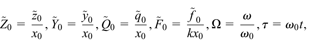
For clarity and simplification of the derivation process, the following variables are introduced:
where represents undamped natural frequencies of the structure, is the static deflection of the spring, is damping ratio, is inertance-to-mass ratio, is the stiffness ratio, , and are the dimensionless displacement amplitudes, is the non-dimensional excitation force amplitude, and denotes the non-dimensional excitation frequency. Equations (7) and (8) are then transformed into
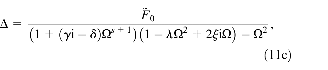
where is the non-dimensional expression of the complex amplitude . Based on equations (1), (6), (9) and (10), the complex response amplitude of the mass and that of the mounting point can be determined
where is the relative displacement of the two ends of the isolator.
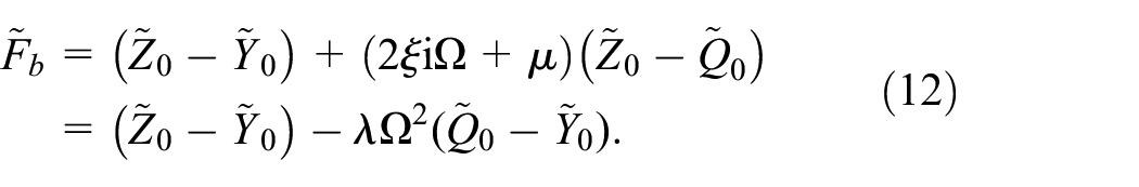
For the vibration isolator with configuration C2, the applied force in the nondimensional form is described by
When this isolator is used, the governing equation of the mass shown in Figure 1(a) is
Thus, the complex displacement amplitude of the mass and that of the mounting point are
Performance indices and vibration power flow analysis
Force transmissibility
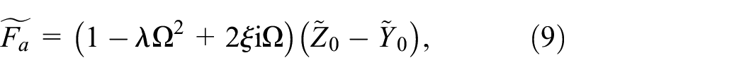
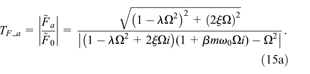
Force transmissibility has been widely used to measure the level of vibration transmission in dynamical systems. It is defined as the ratio between the real response amplitude of the transmitted force (i.e. ) and that of the external excitation force (i.e. ). When the isolator with configuration C1 is used, the amplitude of transmitted force is such that the force transmissibility is formulated by
It shows for the undamped case with , is zero when , suggesting an anti-peak.
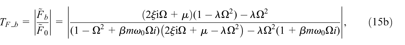
When the isolator C2 is employed, the amplitude of the transmitted force is and thus the force transmissibility is
where the term can be written as when is expressed by equation (6). This equation shows that for the undamped system with , the force transmissibility will be zero when , that is,
This characteristic suggests an anti-peak force transmissibility due to the use of inerter in the isolator C2.
The dimensionless instantaneous input power into the system and the transmitted power to the foundation structure are obtained by taking the product of the excitation force or the transmitted force and the corresponding velocities:
where, and are the instantaneous input power and transmitted power, is the excitation force, is the non-dimensional velocity of mass , is the transmitted force to the base structure, is the velocity of the flexible foundation at position B. In terms of vibration energy transmission within the vibration isolation system, the time-averaged power flow quantities are of interest. The time-averaged input power over a period of oscillation is
where Re{} and * denote the mathematical operations of taking the real part and the complex conjugate of a complex value, respectively. Based on equations 11(a) and 14(a), the time-averaged input power can be expressed as:
for the cases of using C1 and C2, respectively. The time-averaged transmitted power over a period of steady-state vibration is
where is the force transmissibility, denotes the real part of the mobility FRF. When the base is considered as an infinite beam with the mobility function shown in equation (6), the time-averaged transmitted power can be represented by
for configurations C1 and C2, respectively. The equations show that the force transmissibility and the time-averaged vibration power flow variables depend on the mobility of the foundation .
The power transmission ratio can be defined and expressed as:
This variable provides a relative measure of the amount of the averaged input energy that is transmitted into the foundation structure.
Results and discussions
Here the results are presented for different combinations of inerter-based isolators and the flexibility of finite and infinite foundation structures. For validation purpose, finite element (FE) modeling of the finite foundation structure case is employed. In the FE verification, the substructure method is used to derive the steady-state response of the integrated system.41 Configurations C1 and C2 in Figure 1 are divided into several substructures, the unknowns of which are the coupling forces and , as well as the displacements , , and . The dynamic response and vibration transmission behavior can be then obtained by the force balancing and displacement continuity conditions. Figure 1(a) is divided into three parts, that is, the flexible foundation with mobility function , the inerter-based vibration suppression systems C1 and C2, and a vibrating rigid machine subject to a harmonic force excitation of complex amplitude and frequency . The complex amplitudes of the interaction force between these subsystems in C1 and C2 are denoted by and , while the displacements of the vibrating machine and the flexible foundation are represented by and . Note that the displacement of the interface of the inerter and the damper in C2 is denoted by . There are two forces applied to the vibrating machine . One is the external excitation force and the other is the interaction force applied by the passive device and for C1 and C2, respectively.
For validation of the results obtained from the analytical method, finite element model has been built using ANSYS software using Beam 188 element. The foundation structure is discretized into a total number of 100 elements. The geometric and physical properties of the beam used in FE modeling are provided in the subsequent text. A larger number of elements can be used for better accuracy but at a relatively higher computational cost. The beam is considered to be simply supported at its ends. The results obtained from the substructure method based on FEM are denoted by symbols. For generalization of the analysis, non-dimensionless structural and excitation parameters are used to demonstrate the performance evaluation of the proposed inerter-based vibration isolators.
Inerter-based isolator C1 mounted on infinite foundation structure
Here the performance of the inerter-based isolator C1 is evaluated in terms of vibration power flow transmission and force transmissibility. In Figures 3 and 4, the system parameters are set as , , and , suggesting a foundation structure of a low flexibility. The value of the damping ratio suggests a weakly damped system. Weak damping has been widely assumed in the previous investigations and in the practical use of vibration isolators.1 The inertance-to-mass ratio changes from 0.5, to 1, and then to 2, and the corresponding results are shown by dashed, dashed-dotted, and dotted lines. The results corresponding to a conventional spring-damper isolator with are also included and shown by solid lines.
Effects of the inertance-to-mass ratio of the isolator C1 on the dimensionless (a) time-averaged input power and (b) time-averaged transmitted power for an infinite foundation structure of low flexibility ().
Effects of the inertance-to-mass ratio of the isolator C1 on the dimensionless (a) power transmission ratio and (b) force transmissibility , for an infinite foundation structure of low flexibility ().
Figure 3(a) and (b) shows the time-averaged input power and transmitted power , respectively. One resonant peak is observed in each curve of and . The figure also shows that with the increase of the inertance-to-mass ratio, the peaks of and move to the low-frequency range. The peak value of is obtained when the system is excited close to the undamped natural frequency Compared with the conventional spring-damper isolator, the addition of inerter in C1 also introduces anti-peaks at excitation frequency close to in the curves of . This characteristic can be used to reduce vibration transmission to the base structures at a prescribed excitation frequency. With the increase of the inertance-to-mass ratio , the anti-peak frequency reduces, and correspondingly the notches in the curves move to the lower frequencies.
In Figure 4(a) and (b), the effects of the inerters on the power transmission ratio and the force transmissibility are investigated, respectively. Compared with the conventional spring-damper isolator, the use of inerter in C1 introduces anti-peaks at frequency close to in the curves of and . The anti-peak frequency reduces with the increase of the inertance-to-mass ratio . At relatively high excitation frequencies, it is shown that a large inertance-to-mass ratio can lead to higher power transmission ratio as well as a higher level of force transmissibility. This property indicates that the use of inerter may not be beneficial for high frequency vibration isolation. Figures 3 and 4 show that the power flow and vibration transmission characteristics of the system with highly rigid foundation and the inerter-based isolator C1 are similar with those of the single-DOF inerter-based isolator case, as previously investigated.16 A comparison of Figures 3(b) and 4(b) shows that the inerter affects the force transmissibility and the transmitted power in a similar way.
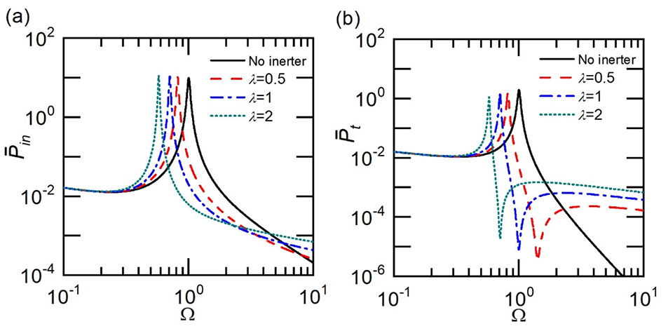
In Figures 5 and 6, the performance of the isolator C1 is evaluated when mounted on a more flexible infinite foundation with . The parameter values are , and three possible values of the inertance-to-mass ratio are chosen to be 0.5, 1, and 2. Compared with the spring-damper isolator case, Figure 5(a) shows that the use of inerter in C1 introduces a local minimum point in the curve of the time-averaged input power at excitation frequency . This characteristic is of contrast to the foundation with low flexibility () case shown by Figure 3(a), in which there is no local minimum point in each curve of . Figure 5(a) shows that as increases from 0.5 to 2, the peak of input power curve moves to the low-frequency range with an increasing peak value. It also shows that the use of C1 as vibration isolator can effectively reduce the amount of vibration energy input into the system within a frequency band. At a prescribed excitation frequency in the high-frequency range, it is shown that an increase in results in a larger . Figure 5(b) shows a resonant peak in each curve of . With the increase of the inertance-to-mass ratio , the corresponding peak value increases but the peak frequency reduces. Compared with the conventional spring-damper isolator case, the inclusion of inerter in C1 on the flexible foundation introduces an anti-peak in the curve at excitation frequency , which can be used to reduce vibration energy transmission to the foundation structure at a specific excitation frequency. With the increase of the inertance-to-mass ratio , this anti-peak shifts to lower frequencies.
Effects of the inertance-to-mass ratio of the isolator C1 on the dimensionless (a) time-averaged input power and (b) time-averaged transmitted power for an infinite foundation structure of high flexibility ().
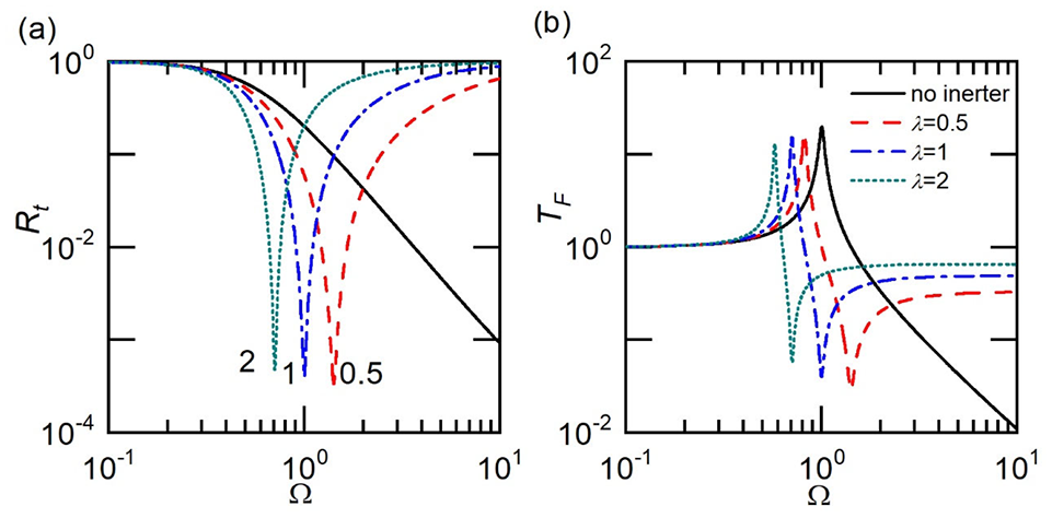
Effects of the inertance-to-mass ratio of the isolator C1 on the dimensionless (a) power transmission ratio and (b) force transmissibility for an infinite foundation structure of high flexibility ().
Figure 6(a) and (b) presents the time-average transmitted power and the force transmissibility to a foundation of a high flexibility. Figure 6(a) shows that there may also be a local minimum point in the curve of due to the use of the inerter in the isolator. The frequency associated with the local minimum reduces as increases. Figure 6(a) demonstrates that in terms of vibration energy transmission, the inerter-based isolator C1 can outperform conventional spring-damper isolator in a range of excitation frequencies. At excitation frequencies with , the changes in is observed to have small influence on vibration power transmission. At a prescribed excitation frequency in the high-frequency range, there may be larger amount of power transmission to the foundation structure due to the increase of , indicating that the inclusions of inerter in configuration C1 may not be beneficial for high-frequency vibration isolation. In Figure 6(b), the use of inerters introduces an anti-peak in each curve of force transmissibility . This characteristic provides a range of excitation frequencies where the force transmission from the mass to the foundation can be greatly reduced. With the increase of inertance-to-mass ratio the peak frequency shifts to lower frequency range, while the corresponding peak value is increased. The impact of inerters in C1 on an infinite foundation structure with high flexibility is negligible at high frequencies.
Inerter-based isolator C2 mounted on infinite foundation structure
Here the vibration transmission characteristics and performance of the inerter-based isolator C2 are investigated from the power flow viewpoint. Figures 7 and 8 consider an infinite foundation of a low flexibility (e.g. high rigidity) by setting while Figures 9 and 10 investigate an infinite foundation structure of high flexibility . In Figures 7 and 8, the other parameters are set as , , . The effects of the inertance-to-mass ratio of the inerter-based isolators C2 on the time-averaged input power , the time-averaged transmitted power , the power transmission ratio , and the force transmissibility are examined and presented. The value of changes from 0.2 to 0.5 and then to 1, and the corresponding results are shown by the dashed, dashed-dotted and dotted lines, respectively. To compare of the isolation performance as well as to reveal the influence of the inerter, the results corresponding to C2 without the inerter, that is, with two springs and connected in parallel with damper , are also included and shown by solid lines.
Effects of the inertance-to-mass ratio of C2 on the dimensionless (a) time-averaged input power and (b) time-averaged transmitted power for an infinite foundation structure of low flexibility ().
Effects of the inertance-to-mass ratio of isolator C2 on the dimensionless (a) power transmission ratio and (b) force transmissibility for an infinite foundation structure of low flexibility ().
Effects of the inertance-to-mass ratio of the isolator C2 on the dimensionless (a) time-averaged input power and (b) time-averaged transmitted power for an infinite foundation structure of high flexibility ().
Effects of the inertance-to-mass ratio of C2 on the dimensionless (a) power transmission ratio and (b) force transmissibility for an infinite foundation structure of high flexibility ().
Figure 7(a) illustrates the impact of the inerter on the time-averaged input power to the machine . One peak is observed for the curve of for the no inerter case. With the addition of the inerter in isolator C2, the original peak for the case without the inerter at moves to higher frequencies with the reduction of , and the corresponding peak value is reduced. Another resonance peak is introduced at the lower frequency range with the use of the inerter in C2, and the peak value is reduced with the increase of and the corresponding peak frequency is also reduced with . Figure 7(b) demonstrates the influence of the inerter on the time-averaged transmitted power . It is shown that there is one resonance peak for at when no inerter is included in the vibration isolator. With the inclusion of the inerter of , this peak shifts to the higher frequency range at , and the corresponding peak value is reduced. There is another resonance peak introduced at , which has the relatively higher peak value compared with the one at . There is an anti-peak between these two peaks at , indicating the potential benefits of using the inerter in terms of power transmission. With the increase of the inertance-to-mass ratio from 0.2 to 0.5 and then to 1, these peaks and the anti-peak shift to the lower frequency range. The peak height of the one at lower frequencies reduced, and the other one as well as the anti-peak value increases with .
Figure 8(a) shows the effects of adding the inerter on the power transmission ratio for isolator C2. It is shown that the addition of the inerter introduces an anti-peak on the curve of , and this anti-peak moves to the lower frequency range with the increase of the inertance-to-mass ratio , and the corresponding anti-peak value is increased. These characteristics indicate the benefits of introducing the inerter in the vibration suppression system from the perspective of vibration transmission ratio. Note that when , an increase of power transmission ratio compared with the case without the inerter is noticed within . When , the curves of four cases tend to merge, indicating that at high frequencies the effect of the inerter is negligible in terms of vibration transmission ratio. Figure 8(b) presents the impact of the inerter on the force transmissibility in C2. One resonance peak is observed at 1.23 when there is no inerter in C2. The inclusion of the inerter shifts this peak to higher frequencies and introduces anther peak in the low-frequency range, which results in an anti-peak between these two peaks. With the increase of the inertance-to-mass ratio from 0.2 to 0.5 and then to 1, these peaks and the anti-peak shift to the lower frequency range. The peak height of the one at lower frequencies reduced, and the other one as well as the anti-peak value increases with .
Figures 9 and 10 present the performance of C2 when mounted on a more flexible infinite foundation with . The parameter values are , , and three possible values of are chosen to be 0.2, 0.5, and 1. Figure 9(a) illustrates the effect of the inerter on the time-averaged input power when C2 is mounted on a relatively flexible structure. The addition of the inerter introduces a resonant peak and an anti-peak in the curve of . The peak and the anti-peak move to the lower frequency range with the increase of the inertance-to-mass ratio , and the corresponding peak and anti-peak values are also increased. When , remains almost the same for four cases, suggesting that the inerter exerts weaker impacts on the input power to machine . Figure 9(b) shows that the use of the inerter in C2 on a flexible foundation introduces a peak and an anti-peak for the curve of . With the increase of , both the peak and the anti-peak in each curve move to the lower frequency range, and the corresponding peak values are increased. The anti-peak introduced by the inerter in Figure 9(b) provides the reduction of the transmitted power to the flexible foundation, indicating that the inerter can be used to reduce the transmitted power.
Figure 10(a) shows the influence of the inerter on the power transmission ratio. It is demonstrated that the addition of the inerter introduces an anti-peak for the power transmission ratio compared with the case without the inerter. With the increase of the inertance-to-mass ratio from 0.2 to 0.5 and then to 1, the anti-peak shifts to lower frequencies and the corresponding anti-peak value increases. This behavior suggests that the inclusion of the inerter can reduce the power transmission ratio at prescribed frequencies when the vibration isolator C2 is mounted on an infinite foundation structure structure of high flexibility. Figure 10(b) illustrates the effect of adding the inerter in C2 on the force transmissibility. It is shown that the inclusion of the inerter in C2 introduces a resonance peak and an anti-peak for the curve of . Both the peak and the anti-peak move to the low-frequency range with the increase of the inertance-to-mass ratio , and the corresponding peak and anti-peak values increase with . These characteristics show benefits of introducing the inerter in terms of the reduction of force transmissibility.
Inerter-based isolator C1 mounted on finite foundation structure
Here the foundation structure is considered to be a finite uniform beam. The vibration power flow behavior and performance of the inerter-based isolator C1 are investigated. Figures 11 and 12 consider a finite foundation by setting , which is an aluminum beam of length. The damping in the isolator is set to be , while the excitation amplitude is . The effects of the inertance-to-mass ratio of the inerter-based isolators C1 on the time-averaged input power and transmit power as well as the power transmission ratio and force transmissibility are examined. The value of changes from 0.5 to 1 and then to 2, and the corresponding results are shown by the dashed, dashed-dotted, and dotted lines, respectively. To compare the isolation performance and also to reveal the influence of the inerter, the results corresponding to the case of a conventional spring-damper isolator are also included and shown by solid lines. The FE results are denoted by symbols.
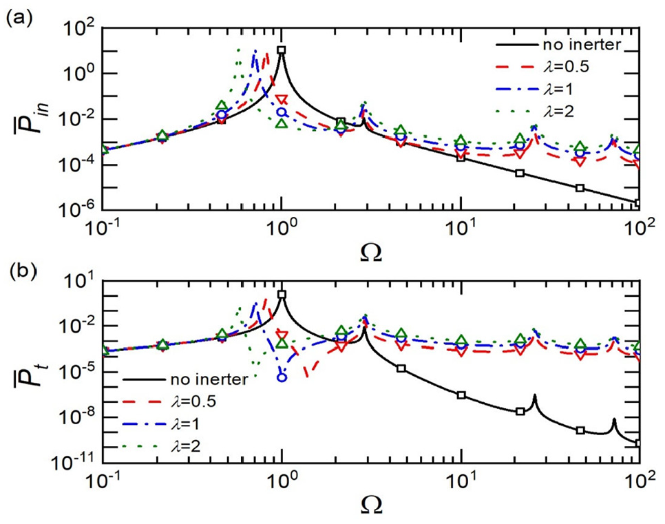
Effects of the inertance-to-mass ratio of C1 on the dimensionless (a) time-averaged input power and (b) time-averaged transmitted power, for a finite uniform beam foundation structure ().
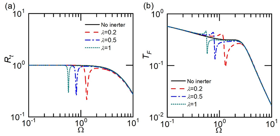
Effects of the inertance-to-mass ratio of C1 on the dimensionless (a) power transmission ratio Rt and (b) force transmissibility, for a finite foundation structure ().
Figure 11(a) shows multiple resonant peaks in the curve of when the foundation is considered as a finite base. It also shows that as the inertance-to-mass ratio increases from 0.5 to 2, the highest peak of each curve shifts left toward the low-frequency range. The other peaks are obtained at similar frequencies for different values of the inertance-to-mass ratio. Compared with the reference system without the inerter, the inclusion of the inerter introduces more peaks at high frequencies. The peak values of increase with in the high-frequency range. The effect of the inerter is negligible when the excitation frequency is small. Figure 11(b) shows that an anti-peak or local minimum point is introduced to the time-averaged transmitted power curve by the addition of the inerter in C1 at . This characteristic can be used to reduce vibration transmission to the base structures at a prescribed excitation frequency. With the increase of the inertance-to-mass ratio, the anti-peak frequency reduces and correspondingly the local minimum point in the curves moves to lower frequencies. The highest peak on each curve moves to the low-frequency range with the increase of . The other peaks, which are obtained at similar frequencies with the change of , become larger with the increase of in the high-frequency range. The effect of inerters at low frequencies becomes negligible when with the curves for different cases merge.
In Figure 12(a) and (b), the influence of the inertance in the isolator C1 on the power transmission ratio and force transmissibility is investigated. In Figure 12(a), multiple peaks in the curve of are observed when there is no inerter in C1. With the inclusion of the inerter, becomes larger at high frequencies and approach to 1 with the increase of . One local minimum point is introduced in each curve of at with the use of an inerter. The corresponding frequency of the local minimum point reduces with the increase of from 0.5 to 2. This behavior can be used to reduce the power transmission ratio at specific excitation frequencies. Figure 12(b) illustrates the force transmissibility from the mass to the foundation structure. It shows that the highest peak moves to the lower frequency range with the addition of the inerter, and the corresponding frequency of these peaks reduces with the inertance-to-mass ratio . The addition of the inerter in C1 introduces an anti-peak to each curve of the force transmissibility at . This characteristic indicates the benefits of using inerter-based vibration isolators at prescribed frequencies. With the addition of the inerter, force transmissibility approaches to a finite value as increases. Also, at a prescribed frequency in the high-frequency range, the value of increases with the value of the inertance-to-mass ratio . At low excitation frequencies, the effects of inerters on the force transmissibility are found to be small.
Inerter-based isolator C2 mounted on finite foundation structure
In this subsection, the use of the inerter-based isolator configuration C2 on a finite foundation structure is investigated. Figures 13 and 14 consider the flexible foundation made of a uniform beam with . The effects of the inertance-to-mass ratio of the inerter-based isolators C2 on time-averaged power flow variables, power transmission ratio, and force transmissibility are examined and presented. The value of changes from 0.2 to 0.5 and then to 1, and the corresponding results are shown by the dashed, dashed-dotted, and dotted lines, respectively. To compare of the isolation performance and also to reveal the influence of the inerter, the results corresponding to a conventional spring-damper isolator are also included in the figures and shown by solid lines. The FE results are denoted by symbols.
Effects of the inertance-to-mass ratio of the isolator C2 on the dimensionless (a) time-averaged input power and (b) time-averaged transmitted power, for a finite foundation structure (, ).
Effects of the inertance-to-mass ratio of C2 on the dimensionless (a) power transmission ratio Rt and (b) force transmissibility, for a finite foundation structure ().
Figure 13(a) shows the influence of adding the inerter in C2 mounted on a finite foundation structure in terms of the time-averaged input power . As shown in Figure 13(a), there are two peaks on the curve of when there is no inerter in C2. With the addition of the inerter, the highest peak in the original system at moves to the higher frequency range. The corresponding peak frequency is reduced with the increase in the inertance-to-mass ratio , and the peak value increases with . Another peak is introduced at lower frequencies, the peak frequency of which reduces with . Figure 13(a) shows the reduction of the time-averaged input power within the limited frequency range when the inerter is added in the vibration suppression system C2 mounted on the finite base structure. Figure 13(b) illustrates the influence of the inerter on the time-averaged transmitted power . The highest peak in the case without the inerter moves to the high- frequency range and the corresponding peak value is reduced with the addition of the inerter. When the inertance-to-mass ratio , the transmitted power is reduced within compared with the case without the inerter, suggesting the vibration is suppressed by using the inerter in terms of transmitted power to the flexible foundation.
In Figure 14(a), the impact of the inerter on the power transmission ratio is investigated. When there is no inerter involved in C2, multiple peaks are observed on the curve of in Figure 14(a). With the inclusion of the inerter, an anti-peak is introduced on each curve of , suggesting that the addition of the inerter provides a reduction of the power transmission ratio in the low-frequency range, which indicates that the inerter is beneficial in vibration suppression from the perspective of power transmission ratio at prescribed frequencies. In Figure 14(b), one resonance peak is observed on the curve of when there is no inerter added in C2. This peak shifts to the high-frequency range with the inclusion of the inerter, and the corresponding peak value increases with and the peak frequency reduces with . Desirable improvement can be found around the anti-peaks arose from the addition of the inerter, where the force transmissibility is reduced significantly, suggesting that the vibration can be suppressed with the addition of the inerter in C2 when the vibration isolator is mounted on a finite structure.
Comparison of configurations C1 and C2
Here the performance of the inerter-based isolators C1 and C2 are compared in terms of transmitted power and force transmissibility . In Figures 15 and 16, the results associated with the uses of C1, C2, and conventional spring-damper isolator are shown by the dashed, dash-dot, and solid lines, respectively. To facilitate comparison, the configuration C2 has a spring , a damper, and an inerter with the identical values as the corresponding parameters for configuration C1. Figure 15 considers an infinite foundation of a low flexibility by setting . The other parameters are set as , , . Figure 15(a) shows that the addition of the inerter in C1 and C2 shifts the peak in the reference system to the lower frequency range. Compared with C1, the addition of the inerter in C2 introduces another peak at higher frequencies. The inclusion of the inerter also introduces an anti-peak in the curve of transmitted power , which leads to the reduction of the power transmission at specific frequencies. Compared with the reference system without the inerter, C1 shows benefits within and C2 has benefits in vibration suppression among . These properties suggest that C1 suppresses more vibration at medium frequencies, while also results in a great increase in transmitted power in the high-frequency range. In Figure 15(b), compared with the reference system without the inerter, C1 provides reduction of force transmissibility within and C2 shows the reduction of within . When the frequency is relatively high, the addition of the inerter in C2 shows an increase of and the increase is stronger in C1 when the excitation frequency is higher. When the frequency is small, that is the effect of the inerter in both C1 and C2 turns to negligible.
Performance comparison of C1 and C2 on an infinite foundation with rigidity () using (a) time-averaged transmitted power and (b) force transmissibility.
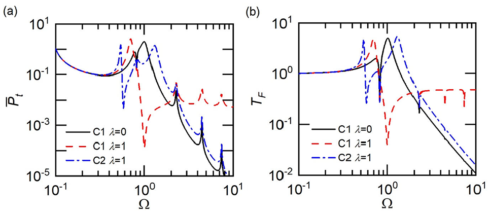
Performance comparison of C1 and C2 on a finite foundation using (a) time-averaged transmitted power and (b) force transmissibility ().
In Figure 16, the performance of C1 and C2 is compared when they are mounted on a finite foundation with . The other system parameters are set as , . Figure 16(a) illustrates the effect of the inerter on the transmitted power. It shows that the addition of the inerter in C1 reduces the transmitted power within compared with the system without the inerter. The use of the inerter introduces an anti-peak at , where the highest peak of is obtained for the case without the inerter. The inclusion of the inerter in C2 on a finite structure has smaller transmitted power when compared with the system without the inerter. These characteristics suggest that the transmitted power from the mass to the flexible foundation can be reduced by adding the inerter in proposed configurations C1 and C2 in the specific frequency range. C1 shows a significant reduction of at , where the anti-peak is obtained. C2 has better performance at high frequencies compared with C1 when . When the excitation frequency is high, both configurations result in an increase in the transmitted power compared with the system without the inerter. Figure 16(b) demonstrates the influence of the inerter on the force transmissibility when configurations C1 and C2 are mounted on the finite structure. Compared with the system without the inerter, the in-parallel configuration C1 provides a lower force transmissibility within and C2 results in the reduction of with the excitation frequency . When the excitation frequency is relatively high, the inclusion of the inerter in both configurations result in an increase in , suggesting that the vibration suppression is weaker compared with the reference system without the inerter. C1 provides a significant reduction of at , while resulting in a great increase of it at high frequencies. C2 provides a substantial decrease of at , with a slight increase of it at high frequencies as well. These properties indicate that the use of the inerter suppresses the vibration at prescribe frequencies in terms of force transmissibility.
Conclusions
The performance of different configurations of inerter-based vibration isolators mounted on a flexible foundation has been investigated in this paper. Both force transmissibility and vibration power flow variables have been used as performance indices. The influence of the flexibilities of a finite beam and an infinite beam foundation structure were examined separately. The results showed that the proposed vibration isolators can significantly suppress vibration at prescribed frequencies in terms of power transmission and force transmission. It was shown that compared to the conventional spring-damper isolator case, the inclusion of the inerter in isolator C1 reduces the vibration transmission greatly at prescribed frequencies near the original peak, at the expense of increasing transmitted power and force in the high-frequency range. The other proposed configuration of isolator C2 can reduce vibration force and power flow transmission in a frequency range around the original peak value while keeping the similar high-frequency isolation performance as that of the corresponding isolator without the inerter. With use of the inerter in the isolators, anti-peaks in the force transmissibility and transmitted power to the foundation structure were generated and the corresponding frequencies were derived analytically to facilitate the isolator design. Using the proposed power flow analysis method, other foundation structures, such as plates and coupled beam-plate structures can be considered for performance assessment of inerter-based isolators.
Footnotes
Appendix
Handling Editor: Chenhui Liang
Declaration of conflicting interests
The author(s) declared no potential conflicts of interest with respect to the research, authorship, and/or publication of this article.
Funding
The author(s) disclosed receipt of the following financial support for the research, authorship, and/or publication of this article: This work was supported by National Natural Science Foundation of China (Grant numbers 12172185, 51605233, 51839005, 51879113) and by Zhejiang Provincial Natural Science Foundation of China (Grant number LY22A020006).
ORCID iD
Jian Yang
Chendi Zhu
Dimitrios Chronopoulos
References
1.
RivinE.Passive vibration isolation. New York, NY: ASME Press, 2003.
2.
XingJTXiongYPPriceWG.Passive–active vibration isolation systems to produce zero or infinite dynamic modulus: theoretical and conceptual design strategies. J Sound Vib2005; 286: 615–636.
3.
LeeC-MGoverdovskiyVNTemnikovAI.Design of springs with “negative” stiffness to improve vehicle driver vibration isolation. J Sound Vib2007; 302: 865–874.
4.
WinterfloodJZhouZBJuL, et al. Tilt suppression for ultra-low residual motion vibration isolation in gravitational wave detection. Phys Lett A2000; 277: 143–155.
5.
XingtianLXiuchangHHongxingH.Performance of a zero stiffness isolator under shock excitations. J Vib Control2014; 20: 2090–2099.
YangJXiongYPXingJT.Dynamics and power flow behaviour of a nonlinear vibration isolation system with a negative stiffness mechanism. J Sound Vib2013; 332: 167–183.
8.
SmithMC.Synthesis of mechanical networks: the inerter. IEEE Trans Automat Contr2002; 47: 1648–1662.
9.
JiangJZMatamoros-SanchezAZGoodallRM, et al. Passive suspensions incorporating inerters for railway vehicles. Veh Syst Dyn2012; 50: 263–276.
10.
LiYJiangJZNeildS.Inerter-Based configurations for main-landing-gear shimmy suppression. J Aircr2017; 54: 684–693.
11.
LuoJJiangJZMacdonaldJHG. Cable vibration suppression with inerter-based absorbers. J Eng Mech2019; 145: 04018134.
12.
LazarIFNeildSAWaggDJ.Using an inerter-based device for structural vibration suppression. Earthq Eng Struct Dyn2014; 43: 1129–1147.
13.
ZhangSYJiangJZNeildS.Optimal configurations for a linear vibration suppression device in a multi-storey building. Struct Control Health Monit2017; 24: e1887.
14.
ZhangRZhaoZPanC, et al. Damping enhancement principle of inerter system. Struct Control Health Monit2020; 27: e2523.
15.
ZhuCYangJRuddC.Vibration transmission and power flow of laminated composite plates with inerter-based suppression configurations. Int J Mech Sci2021; 190: 106012.
16.
YangJ.Force transmissibility and vibration power flow behaviour of inerter-based vibration isolators. J Phys Conf Ser2016; 744: 012234.
17.
YangJJiangJZZhuX, et al. Performance of a dual-stage inerter-based vibration isolator. Procedia Eng2017; 199: 1822–1827.
18.
DongZYangJMengH, et al. Suppression of vibration transmission between oscillators coupled with an inerter-based joint. In: Proceedings of the international conference on structural dynamics (EURODYN), Athens, Greece, 2020, vol. 1, pp.1521–1528.
19.
MuhammadSWangSLiF, et al. Bandgap enhancement of periodic nonuniform metamaterial beams with inertial amplification mechanisms. J Vib Control2020; 26: 1309–1318.
20.
DongZChronopoulosDYangJ.Enhancement of wave damping for metamaterial beam structures with embedded inerter-based configurations. Appl Acoust2021; 178: 108013.
21.
YangJJiangJZNeildSA.Dynamic analysis and performance evaluation of nonlinear inerter-based vibration isolators. Nonlinear Dyn2020; 99: 1823–1839.
22.
SugiuraKWatanabeYAsaiT, et al. Experimental characterization and performance improvement evaluation of an electromagnetic transducer utilizing a tuned inerter. J Vib Control2020; 26: 56–72.
23.
LageYENevesMMMaiaNM, et al. Force transmissibility versus displacement transmissibility. J Sound Vib2014; 333: 5708–5722.
24.
GoyderHGWhiteRG.Vibrational power flow from machines into built-up structures, part I: introduction and approximate analyses of beam and plate-like foundations. J Sound Vib1980; 68: 59–75.
25.
GoyderHGWhiteRG.Vibrational power flow from machines into built-up structures, part II: wave propagation and power flow in beam-stiffened plates. J Sound Vib1980; 68: 77–96.
26.
GoyderHGWhiteRG.Vibrational power flow from machines into built-up structures, part III: power flow through isolation systems. J Sound Vib1980; 68: 97–117.
27.
LangleyRS.Analysis of power flow in beams and frameworks using the direct-dynamic stiffness method. J Sound Vib1990; 136: 439–452.
28.
ClarksonBL.Estimation of the coupling loss factor of structural joints. Proc IMechE, Part C: J Mechanical Engineering Science1991; 205: 17–22.
29.
CuschieriJM.Structural power-flow analysis using a mobility approach of an L-shaped plate. J Acoust Soc Am1990; 87: 1159–1165.
30.
MaceBRShorterPJ.Energy flow models from finite element analysis. J Sound Vib2000; 233: 369–389.
31.
WangZHXingJTPriceWG.A study of power flow in a coupled plate–cylindrical shell system. J Sound Vib2004; 271: 863–882.
32.
XiongYPXingJTPriceWG.Power flow analysis of complex coupled systems by progressive approaches. J Sound Vib2001; 239: 275–295.
33.
XingJTPriceWG.A power–flow analysis based on continuum dynamics. Proc R Soc London Ser A1999; 455: 401–436.
34.
JiLMaceBRPinningtonRJ.A power mode approach to estimating vibrational power transmitted by multiple sources. J Sound Vib2003; 265: 387–399.
35.
XiongYPXingJTPriceWG.A power flow mode theory based on a System’s damping distribution and power flow design approaches. Proc R Soc A Math Phys Eng Sci2005; 461: 3381–3411.
36.
YangJXiongYPXingJT.Nonlinear power flow analysis of the Duffing oscillator. Mech Syst Signal Process2014; 45: 563–578.
37.
YangJXiongYPXingJT.Vibration power flow and force transmission behaviour of a nonlinear isolator mounted on a nonlinear base. Int J Mech Sci2016; 115-116: 238–252.
38.
YangJXiongYPXingJT.Power flow behaviour and dynamic performance of a nonlinear vibration absorber coupled to a nonlinear oscillator. Nonlinear Dyn2015; 80: 1063–1079.
39.
LiangQLiL.Optimal design for a novel inerter-based clutching tuned mass damper system. J Vib Control2020; 26: 2050–2059.
40.
OliveiraFBottoMAMoraisP, et al. Semi-active structural vibration control of base-isolated buildings using magnetorheological dampers. J Low Freq Noise Vib Active Control2018; 37: 565–576.
41.
WangZHXingJTPriceWG.Power flow analysis of indeterminate rod/beam systems using a substructure method. J Sound Vib2002; 249: 3–22.