
Abstract
In this study, the applications of the cubic power law damping in vessel isolation systems are investigated. The isolation performance is assessed using the force transmissibility of the vessel isolation system, which is simplified as a multiple-degree-of-freedom system with two parallel freedoms. The force transmissibilities of different working conditions faced in practice are discussed by applying the cubic power law damping on different positions of the vessel isolation system. Numerical results indicate that by adding the cubic power law damping to an appropriate position, the isolation system can not only suppress the force transmissibility over the resonant frequency region but also keep the force transmissibility unaffected at the nonresonant frequency region. Moreover, the design of the nonlinear vessel isolation system is discussed by finding the optimal nonlinear damping of the isolation system.
Introduction
Vessels have been widely applied in the survey of marine resources. The vibration and noise of the vessel system are curial to its stability and comfort in engineering practice.1,2
In the vessels’ vibration isolation systems, linear damping is often applied by many literatures to reduce the output amplitude and the force transmitted to the base, which is known as the transmissibility of the system.3,4 However, by using linear damping isolators, the transmissibility of the resonant region is suppressed, but the transmissibility of the nonresonant region can be increased.
5
In order to address this problem, many nonlinear vibration isolation approaches, such as the quasi-zero stiffness (QZS),
6
For example, Yang et al.
10
presented an active–passive vibration isolation approach by establishing a mathematical model of the floating raft system, and the
Most recently, Lang and colleagues14–16 introduced the power law nonlinear damping and nonlinear stiffness into the vibration isolation system. Ho et al. 15 investigated the effects of spring nonlinearity on the power transmissibility. In Lang et al., 17 the effects of nonlinear viscous damping on single-degree-of-freedom (SDOF) structures were analyzed. The output frequency response function (OFRF) was employed to determine the relationships between the force transmissibility and the system characteristic parameters, such as to systematically facilitate the analysis and design of nonlinear system.18,19 Peng et al.20,21 investigated the force transmissibility of series MDOF structures with a cubic nonlinear damping, demonstrating that a cubic power law viscous damping can achieve a better vibration isolation performance and overcame the disadvantages of linear damping. Mofidian et al. 22 presented the theory and experimental study about the combination of magnetic springs and viscous and magnetic damping.
It is worth pointing out that, most nonlinear damping theory investigations of the vibration isolation system focused on the SDOF and series MDOF structures. However, for vessel isolation systems, the structures are complex and usually of unchain type, which can provide more abundant isolation phenomenon than the SDOF and series MDOF structures. In this study, the MDOF structure with parallel freedoms is applied to represent the vessel isolation system. Moreover, the application of the cubic power law damping is, for the first time, discussed based on the parallel MDOF system under different working conditions. Finally, the optimal design of the vessel isolation system is conducted, and the design requirements and process are summarized.
Nonlinear damping–based vessel isolation system
Mechanical structure of the isolation system
The vessel isolation system simplified from laboratory equipment is depicted in Figure 1(a), where the two diesel engines are the vibration sources. Diesel engines and other equipments are installed on the middle support together. Four dampers are set on the bottom of the each diesel engine, shown as the blue circle in Figure 1(b). Under the middle support, there are six uniformly distributed springs and dampers, shown as the triangle in Figure 1(b).
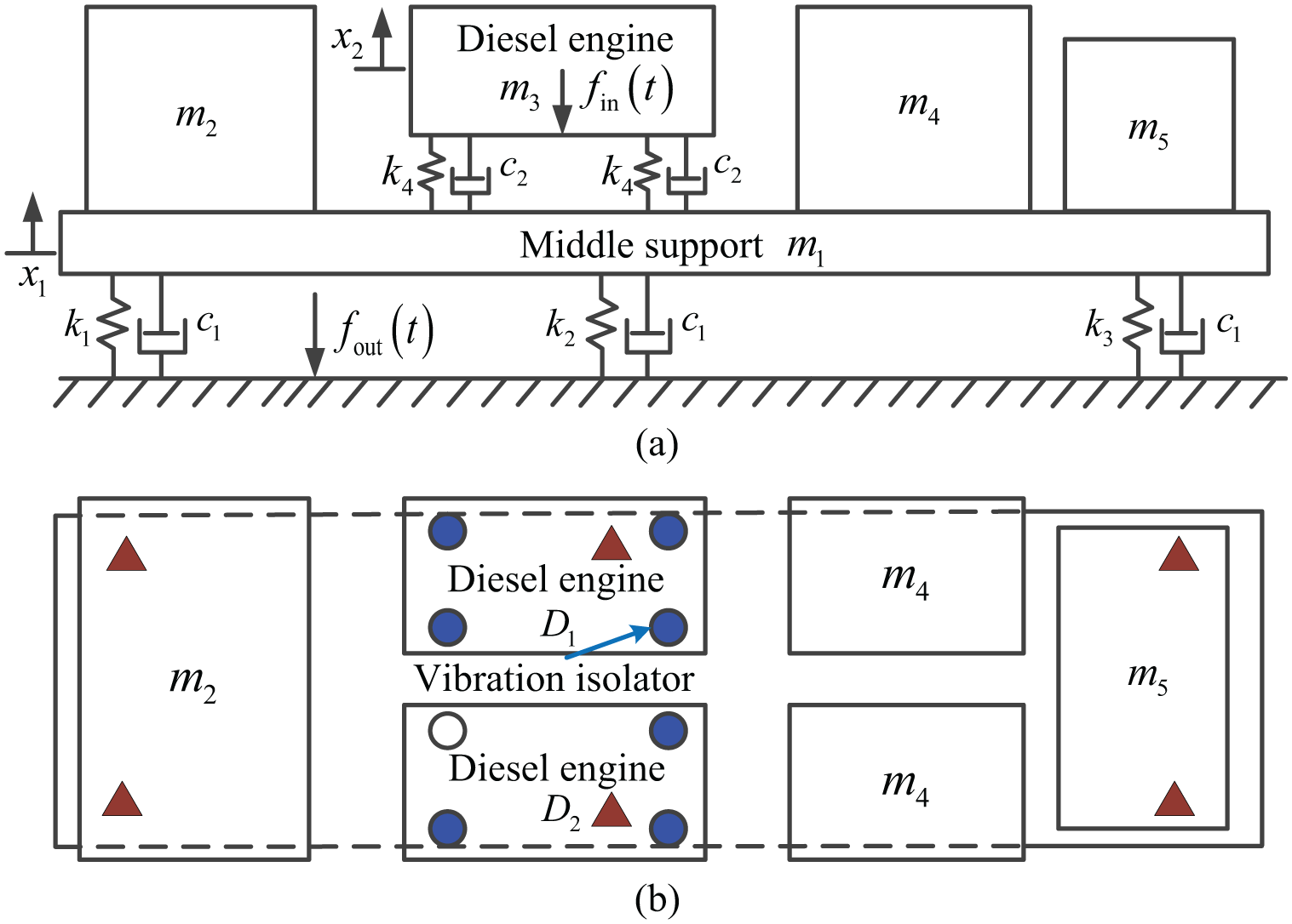
Structural characteristics of the vibration isolation system: (a) front view and (b) top view.
In the proposed vessel isolation system,
Under the middle support, the stiffness values of the left, middle, and right springs are
Assuming the middle support is rigid, the vessel isolation system in Figure 1 can further be simplified as a 3-DOF system with two parallel freedoms, shown in Figure 2.
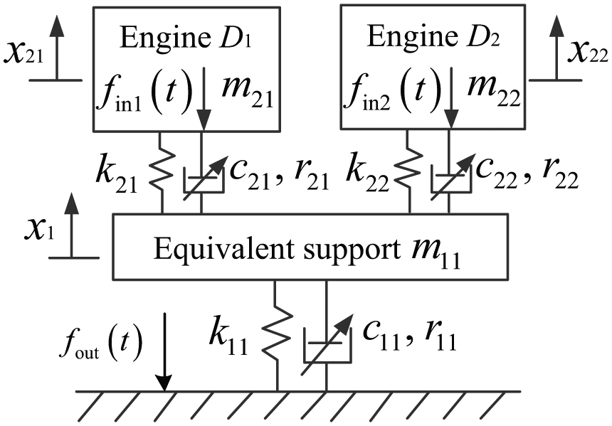
Simplified structure of a vibration isolation system with a cubic power law damping.
Symbols in Figure 2 are defined as follows:


Transmissibility of the isolation system
The differential equation of the isolation system can be written as

where
Considering that input force generated by the diesel engine is harmonic yields

where
Consider only one diesel engine works, the force transmissibility of the isolation system is defined as the ratio of the output force spectrum with respect to the input force spectrum, 23 which can be expressed as

where

where
When two diesel engines synchronously work, the transmissibility is defined as

where
In the following studies, the transmissibilities of the ground and the unworked engine are considered, where the transmissibility analysis for
Numerical analysis of the nonlinear vessel isolation system
In order to investigate the vibration transmissibility characteristics of an isolation system and the effects of a cubic nonlinear damping characteristic on the force transmissibility, numerical analysis was conducted on a vessel isolation system to calculate the force transmissibility. It is worth noting that, many numerical methods, such as the Newmark method 24 and the Runge–Kutta method, 20 can also be used to compute the system output responses. In this study, the Runge–Kutta method and the Fourier transform are applied to analyze the vibration transmissibility of the vessel isolation system.
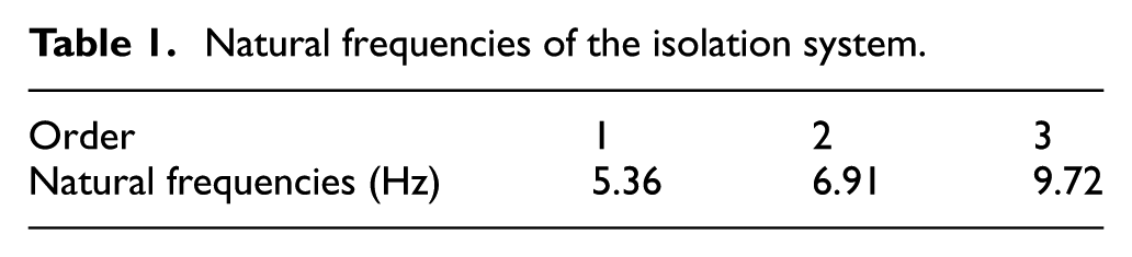
For the isolation system in Figure 2, the previous three orders’ natural frequencies of the system can be numerically obtained as listed in Table 1.
Natural frequencies of the isolation system.
In the following studies, two working conditions will be discussed for the isolation system, including single diesel engine and double diesel engine rotating synchronously. The effects of both linear and nonlinear damping are discussed under these working conditions, such as to illustrate the advantages of nonlinear damping in the vessel isolation systems.
Single diesel engine rotating
Considering the isolation system works with single diesel engine rotating, for example, the diesel engine
The input force
Therefore, the force transmissibility in equation (5) can be simplified as

and the effects of both linear and nonlinear damping on the force transmissibility
Effects of linear damping
The values of linear damping are assumed to be proportional to the stiffness values


where
The linear and nonlinear damping ratios can be determined based on the study of Peng et al.
20
and contained the light and strong damping values. Furthermore, based on the vibration isolation system, the damping ratios are optimized according to the numerical analysis and ensured in the available range. Given the linear damping ratio

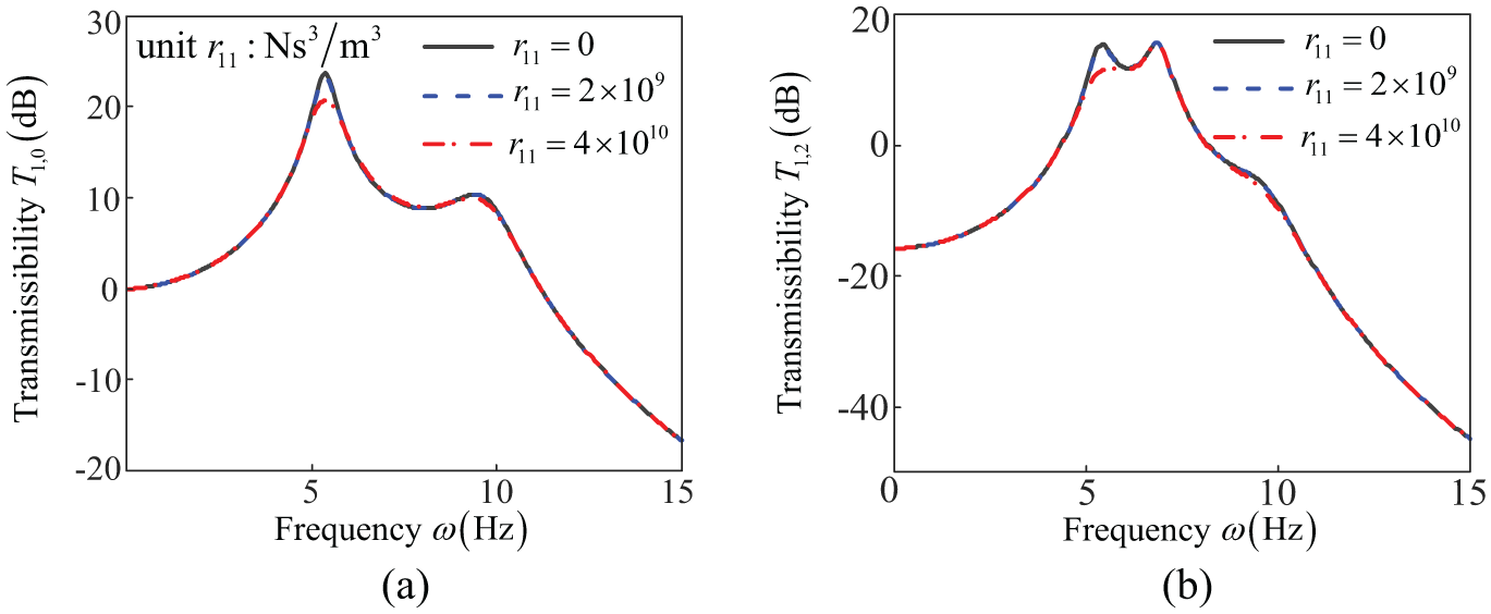
Force transmissibility analysis with linear damping parameter

Force transmissibility with the linear damping parameter
As indicated in Figures 3(a), 4(a), and 4(b), the force transmissibility
However, in Figure 3(b), only the second-order resonant frequency remains when the linear damping
This is because, the mass, stiffness, and damping values of the parallel diesel engines
In the next section, the nonlinear damping technique will be applied to improve these unexpected isolation performance for a parallel MDOF isolation system.
Effects of nonlinear damping
Two cases will be discussed in this section, where nonlinear damping is applied under the equivalent mass
Considering that a cubic power law damping
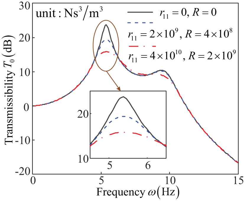
Force transmissibility with different nonlinear damping

Transmissibility analysis with different nonlinear damping R. The force transmissibility (a)
In Figures 5 and 6, the results indicate that the power law damping can not only suppress the force transmissibilities
These results indicate that the isolation performance of the vessel isolation system can be optimized by applying nonlinear damping. Before conducting the optimized design of the nonlinear damping based on the vessel isolation system, another operating condition, where the double diesel engines rotate synchronously, is briefly discussed as follows, indicating the optimization is also needed in this case with a nonlinear damping.
Synchronous rotation of double diesel engines
When the two diesel engines rotate synchronously, the isolation system in Figure 2 can readily be simplified as a 2-DOF system as shown in Figure 7.

2-DOF vibration isolation system.
The equivalent input force

Both power law damping
Effects of power law damping
The results discussed above indicate that, the vessel isolation system with two engines working synchronously can be simplified as a 2-DOF system, which has been well studied for the analysis and design problems. 20
In addition, the finite element simulation and experiments will be conducted in the further investigation. In the next section, an optimal design of the vessel isolation system is studied with only one diesel engine working.
Design of the vessel isolation system
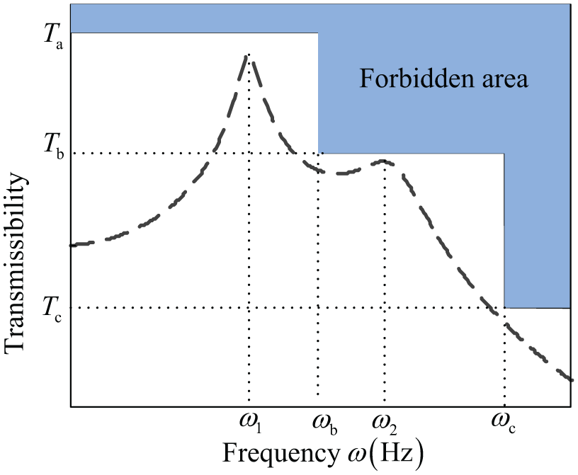
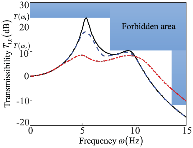
The design restrictions of the vessel isolation system are depicted in Figure 9, where the force transmissibility curve cannot be presented in the forbidden area. 15 For the working condition of single diesel engine rotating, the design requirements are described as
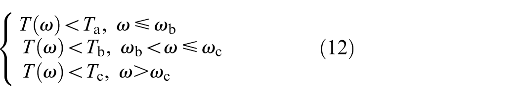
where
Design restrictions of the vessel isolation system.
Equation (12) limits the force transmissibility of the nonresonant region by adopting a less significant linear damping, as well as restricts the resonant peak values of the force transmissibility by increasing the nonlinear damping parameters. The ideal transmissibility curve of a vessel isolation system must lie in the white region by designing the linear and nonlinear damping.
The design issue can be described as an optimal design problem as follows:
Find

Solve the optimization problem

Under the constraint of

Design steps
Assuming that mass and stiffness parameters of the vibration isolation system are fixed, the damping parameters can be determined in three steps to achieve the design requirements. First, considering that the linear damping will increase the force transmissibility in the isolation range of
Step 1. Determination of linear damping characteristics
Assuming the vibration isolation system only has linear damping forces,
Step 2. Designing nonlinear damping R and
In order to satisfy equation (12), the strong nonlinear damping
Force transmissibility with double nonlinear damping where
For the vibration isolation system, the nonlinear damping values can be determined as
Step 3. Compare the results and requirements
If
If the force transmissibility is violated for
If the force transmissibility of the second-order resonant frequency is not satisfied with equation (12), the linear damping
The optimization process is summarized in Figure 11.

Optimization process of the damping parameters.
Conclusion
In this article, the power law nonlinear damping was studied based on a parallel 3-DOF nonlinear system simplified from a vessel isolation system in laboratory. Two working conditions, including the single diesel engine rotating condition and the double diesel engine rotating condition, were investigated, where the effects of the power law damping on the force transmissibility of the system were investigated. Furthermore, the design of the power law damping was discussed. The detailed conclusions are given as follows:
Nonlinear damping has a better performance than linear damping in isolating the vessels’ vibration. The force transmissibilities over all frequency ranges are relatively low under different working conditions.
With the single diesel engine rotating, three resonant peaks can be observed in the plot of the force transmissibility
With the single diesel engine rotating, the force transmissibility
The design process of the power law damping was presented by determining the linear and nonlinear damping characteristics under a given forbidden area. Strong nonlinear damping can increase the transmissibility over the nonresonant region.
Footnotes
Appendix 1
Handling Editor: Yunn-Lin Hwang
Declaration of conflicting interests
The author(s) declared no potential conflicts of interest with respect to the research, authorship, and/or publication of this article.
Funding
The author(s) disclosed receipt of the following financial support for the research, authorship, and/or publication of this article: This study was financially supported by the Youth Innovation Promotion Association Foundation of the Chinese Academy of Sciences (grant no. 2016187) and the Key Research Program of the Chinese Academy of Sciences (grant no. KGFZD-135-16-006).