
Abstract
Cross-section profile of rotor takes a great effect on the performance of dry-screw vacuum pump. A novel smooth rotor profile consisting of eight segments of curves, including arcs and conjugate correction curves is proposed. Advantages are that it can be used to solve the unsmooth connection and no meshing clearance in traditional profile. The meshing model for new profile can directly generate stable addendum clearance, tooth clearance, tooth side clearance, and radial clearance. The influences of the epicycloid rotation angle, arc radius and involute offset distance of the conjugate correction curve on the clearances are studied according to established theoretical model. And transient flow field of vacuum pump is analyzed by using the commercial software Ansys-Fluent®. Compared to traditional screw vacuum pump, the results shows that pressure in inlet and pump cavity is lower, and maximum pumping speed is higher, indicating that the proposed design is superior.
Keywords
Introduction
The dry-screw vacuum pump is a kind of vacuum acquisition equipment without any lubrication activities in the cavity, which is working clearances between each other and no direct contact among screw rotors, rotor, and pump cavity. The screw rotor is the key critical and complex part for this kind of vacuum pump and its cross-section profile is the primary factor to determine the structure of rotor and to take a great effect on the performances of vacuum pump.1–3
Pfaller et al. 4 proposed a strategy for the energetic optimization of a screw spindle vacuum pump by means of the variable pitch of a rotor at constant design volume, and numerically simulated energy-specific optimal rotor pitch based on the evolutionary optimization approach. Pfaller et al. 5 established a model that is a function of chamber pressures and mass flows of dry-running screw pump, and illustrated the relationship among working chamber volumes, stage pressure rations and isentropic compression work for different suction pressures. Cheng and Chiang 6 used fluid dynamics method to estimate the pumping performance of a turbobooster vacuum pump, with spiral-grooved rotor and inner housing. Giors et al. 7 developed a Navier-Stokes model of a Holweck pump with tapered pumping, and used FLUENT to predict the pressure profile along the grooves. Rabiger et al. 8 utilized a finite volume model to analyze the distributions of velocity, pressure, and temperature of the twin-screw pump clearances. Ryazantsev and Plyasov 9 demonstrated the relationship between screw clearance and deflection. Li et al. 10 analyzed the effect of key parameters on the generation and conical rotors in conical rotors. Utri et al.11,12 optimized the variable lead rotor pair for an industrial air screw compressor via high number of rotor segments attaining to a uniformly varying lead. Straalsund et al. 13 validated an Archimedes hydrodynamic screw three-dimensional printed models based on a bench-scale performance test, and the various shapes and parameters have been verified. Zöllig 14 found that energy consumption of variable-pitch rotor was lower in the degassing process of compressing screw vacuum pumps and Roots pumps. Rane et al. 15 designed a new un-traditional rotor using variable lead or profile variations, and performance of rotors was tested by SCORG software. The characteristic parameters, that is, suction speed and final attainable pressure of dry-running screw vacuum pump were investigated by Dirk et al. 16 Salikeev et al. 17 presented a prompt conductance calculation method for slot channels with the minimal clearance at a certain point along gas flow direction, which was used for the modeling the process of scroll pumps, claw pumps and Roots pumps. Patil and Morrison 18 investigated the effect of heat generation during the period of wet gas compression on the pump performances and potential mitigation measures to consequential issues for fixed flow rate of seal flush-fluid recirculation. Burmistrov et al. 19 used the angular coefficients method to calculate the channels conductance with more complicated profiles, such as working in the molecular flow regime of Roots pumps. Salikeev et al. 20 defined the channels conductance of vacuum and compressor, which was formed by cylindrical walls and rectangular channels within a wide range of geometrical dimensions, inlet pressures and pressure ratios with Navier-Stokes equations system. Salikeev et al. 21 calculated conductance coefficients of slot channels formed by cylindrical walls using the Monte Carlo method with different wall radius and clearances. Salikeev et al.17,22 proposed the relationships of conductance calculations using three types of slot channels in viscous flow regime under small pressure differences at the end of the channel, and modeling the pumping process of scroll pumps, claw pumps and Roots pumps. Liu et al. 23 proposed optimization method of multi-stage multiphase pump and applied to optimize the inlet blade Angle of the next stage impeller. Liu et al. 24 investigated the pressure fluctuations and flow patterns in a centrifugal pump without and with 2D or 3D inlet guide vanes by numerically simulation. Xiao and Tan 25 proposed a design method of controllable velocity moment in combination of singularity method for multiphase pump, and combined with the orthogonal optimization method to suppress the pressure fluctuation in pump.
The screw rotor or the cross-section profile of rotor as mentioned above are characterized by the sharp points resulting in the wear aggravation. The formed rotor meshing model fails to directly generate stable clearances, and the meshing model forms a leakage triangle leading to the gas leakage. In this paper, a novelty cross-section profile (NCSP) is proposed consisting of eight segments of curves, which are the arcs, epicycloid conjugate correction curve, involute conjugate correction curve, etc. Meshing model has stable tooth clearance, tooth side clearance and radial clearance. The influence of correction curve parameters on clearances is studied. Based on the CFD simulation technique, three-dimensional transient flow field of screw vacuum pump is simulated. Detailed comparisons using inlet pressure, gas pumping speed and pump cavity pressure between NCSP and traditional pump is investigated.
Analysis of conjugate curves of rotor profile
Common conjugate curves
The traditional cross-section profile (TCSP) is shown in Figure 1 consisting of the epicycloid, dedendum circle, involute and addendum circle. Curves profile of male and female rotors are the same by the coordinate transformation.
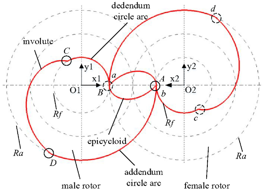
The TCSP.
The conjugate curves of involute in the TCSP are shown in Figure 2. In the O1x1y1 coordination system, the involute is generated by rolling on the base circle with radius R0 and center point O1. Its conjugate curve is transformed into the involute in system O2x2y2, it is


The conjugate curves of involute.
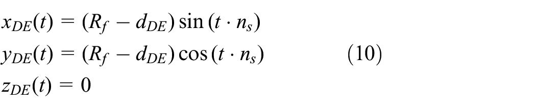
The conjugate curves of epicycloid in the TCSP are shown in Figure 3, which is the track point on the circumference of a moving circle with radius Rf rolling along the fixed circle. Its conjugate curve is the epicycloid in system O2x2y2 and its equation is

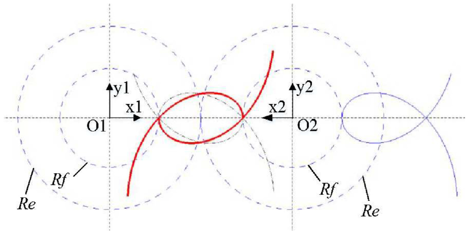
The conjugate curves of epicycloid.
Conjugate correction curves
As shown in Figure 4, the offset correction involute is obtained by the offset distance d along the concave or convex directions, its modified equation is

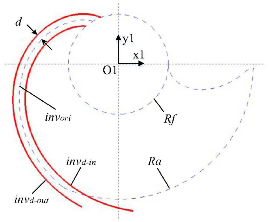
Involute offset correction model.
Where, ee is the adjusted offset parameter, the offset curve invd-in in the concave direction is negative, the offset curve invd-out in the convex direction is positive.
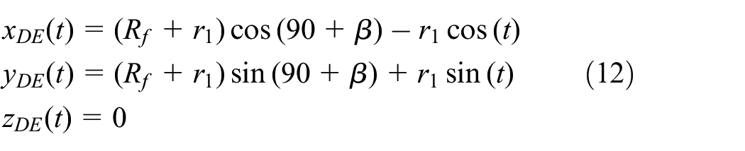
As shown in Figure 5, the offset correction epicycloid is obtained by the offset distance d along the concave or convex direction, modified equation is

Where ee′ = ±ee, the offset curve epid-in in the concave direction is positive, the offset curve epid-out in the convex direction is negative.
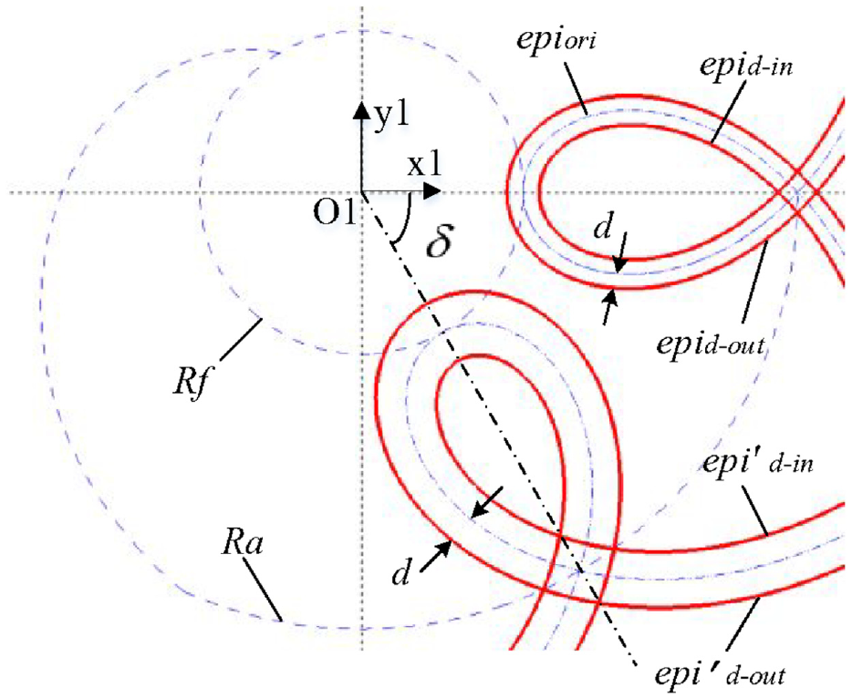
Epicycloid correction model.
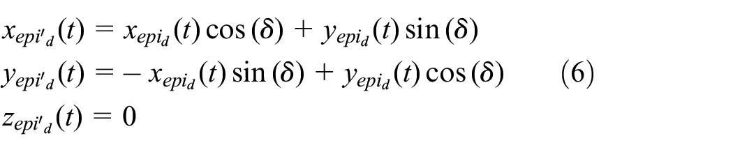
As shown in Figure 5, the concave direction rotation offset curve epi′d-in and convex direction rotation offset curve epi′d-out are obtained by rotating the angle δ of the curve epid-in and epid-out, its modified equation is
The meshing process model of the TCSP screw rotor is shown in Figure 6, and the rotor has the following disadvantages.
There are sharp points or unsmooth connection points, such as A, B, C, D, a, b, c, d in the TCSP (see Figure 6(a)) leading to the wear near the screw rotor unsmooth edge. Thus, increasing the meshing clearance can weak the working performance of screw vacuum pump.
The edges of unsmooth points C and d in the TCSP rotor are easily to form the discontinuous contact lines in the meshing process as a result of gas leakage and leakage triangle (see Figure 6 (b))
The rotor meshing surfaces are in contact with each other that can not directly form the required stable clearances. Reliable clearances ensure the good performances of the screw vacuum pump.
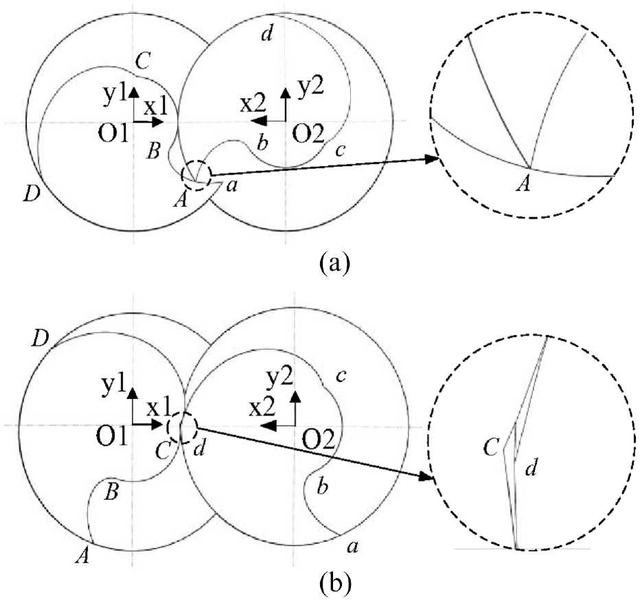
The meshing process model of the TCSP rotor: (a) profile spire points and (b) leakage triangle.
Design method of the NCSP
A geometric model
A novel meshing clearance optimization is proposed. Previous patterns of cusps, epicycloid and involute of the TCSP are replaced by the eight kinds of curves, that is, arcs and conjugate correction curves etc. (see Figure 7). Points A B, C and D in the TCSP are replaced by arcs AB, CD, EF, and GH for accomplishment of smooth transition. Stable meshing clearances are obtained by replacing the original epicycloid with the rotation offset curve epi′d-in along concave direction and the original involute with the offset curve invd-in along concave direction.
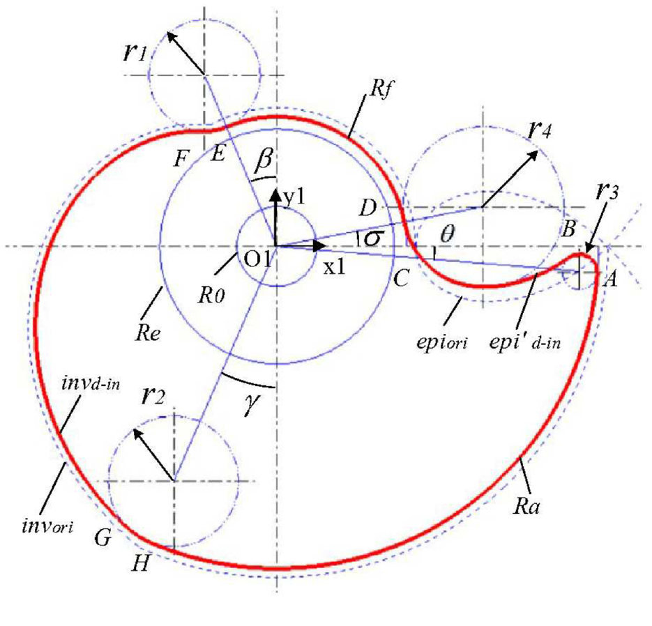
The NCSP.
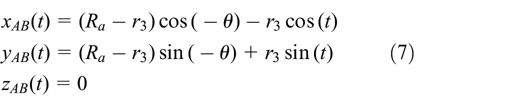
AB is arc and its equation is
BC is the correction epicycloid and its equation is

CD is arc and its equation is

DE is dedendum circle arc and its equation is
where

EF is arc and its equation is
FG is the correction involute and its equation is

GH is arc and its equation is

HA is addendum circle arc and its equation is

Where

Meshing model of the NCSP with clearances
Both male and female rotors of the NCSP are generated by the spiral motion. After the two rotors are meshed, the addendum clearance, tooth clearance, tooth side clearance, and radial clearance can be directly generated. Clearances are evenly distributed from the suction end to the exhaust end (see Figure 8).
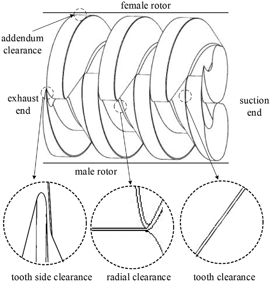
The meshing model of the NCSP with clearances.
Discussions NCSP
When epicycloid rotation angle δ equals C, radius r3 will affect the shape of rotor profile (see Figure 9). The larger radius, the shorter epicycloid BC, point B is readily to escape away from the horizontal line. Therefore, tooth side clearance is formed. Figure 10 shows the relationship between radius and the tooth side clearance when the angle δ is changing from 4.8° to 5.2°. If angle δ remains to be stable, the tooth side clearance decreases with the decreasing radius. Angle δ smaller, the tooth side clearance is larger when radius r3 is constant.

The NCSP varying with r3: (a) r3 = 0 mm, (b) r3 = 1.5 mm, (c) r3 = 3 mm, and (d) r3 = 5 mm.
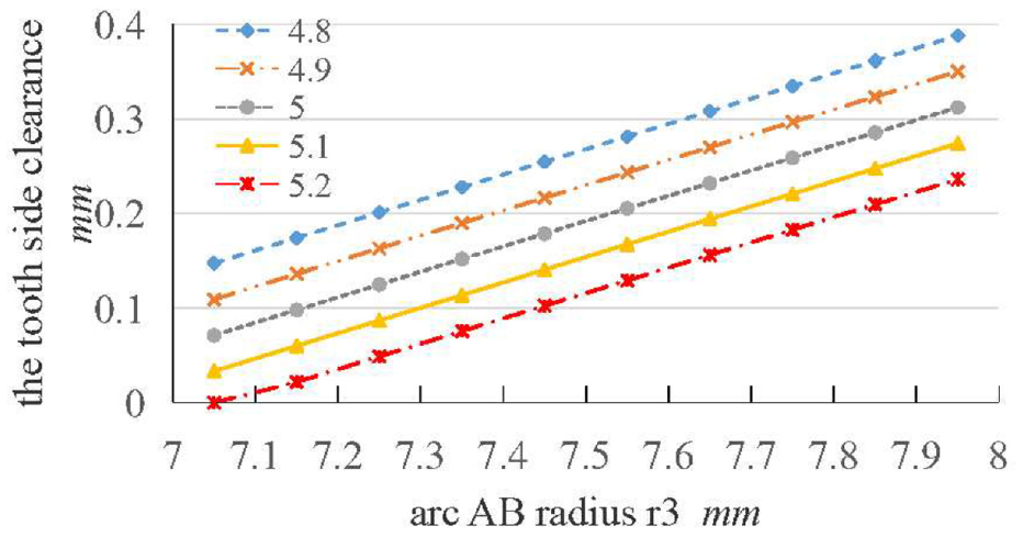
The relationship between r3 and the tooth side clearance.
When radius δ equals C, angle δ affects the shape of rotor profile (see Figure 11). With angle δ in increase, the more epicycloid BC deflects to concave direction and larger radius is needed to generate the tooth side clearance.

The NCSP varying with δ: (a) δ = −2.5°, (b) δ = −5°, (c) δ = −7.5°, and (d) δ = −10°.
Tiny radius r3 leads to the interference of the meshing rotor. When angle δ equals 5.2°and radius r3 = 7.05 mm, the tooth side clearance is zero, and the meshing rotor interferes. As shown in Figure 12, when radius r3 = 7.25 mm, increasing angle δ leads to the decrease in tooth side clearance.

The relationship between δ and the tooth side clearance.
When angle δ attaining to a certain extent, the meshing rotors keeps the interference rather than the formation of tooth side clearance.
When geometric parameters of the rotor are constants, the involute offset distance d affects the shape of rotor profile (see Figure 13). The involute is offset to the concave direction to form the tooth clearance.

The NCSP varying with d: (a) d = 0 mm, (b) d = 2 mm, (c) d = 3.5 mm, and (d) d = 5 mm.
As shown in Figure 14, by adjusting the involute offset parameter ee in equation (13), the relationship between this parameters and distance is obtained. With the increasing ee, both involute offset distance d and tooth clearance of meshing model increase. But tooth clearance is not equal to the sum of offset distance d of the male and female rotors. Relative variation of tooth clearance and offset distances d is less than 18%. Therefore, one half of the tooth clearance cannot be obtained by adjusting the involute offset distance d regarding the designation of tooth clearance.

The relationship between ee and distance.
Comparisons of NCSP and TCSP screw vacuum pumps
The same sizes NCSP and TCSP rotors are set to Ra = 74 mm, Rf = 31 mm, Re = 52.5 mm, and R0 = 18 mm, pitch lead is 80 mm, addendum clearance is 0.33 mm, tooth clearance is 0.35 mm, tooth side clearance is 0.12 mm and radial clearance is 0.48 mm. Geometric parameters of NCSP are δ = 5°, r3 = 7.25mm, ee = 1.1°, and dDE = 0.15 mm.
Numerical simulation
The fluid domain is divided by unstructured meshes and k-ε two-equation model built-in the commercial software ANSYS are utilized. The semi-implicit pressure linked equations-corrected (SIMPLEC) algorithm to correct p-v correlation with tri-diagonal marching algorithm (TDMA) line-by-line iteration, under-relaxation quadratic upstream interpolation, convective kinematics (QUICK) procedure and the central difference scheme (CDS) for the diffusion terms are made for the solution of the finite differential equations and this algorithm will be improved in the future based on our previous works.26–28 The pressure boundary condition is set to the inlet and outlet, and the velocity boundary condition is set to the outer surface of the rotors. The boundary conditions are listed as follows: the inlet pressure is 861 Pa, outlet pressure is about 101,325 Pa, the female rotor speed is approximately 2900 r/min, the male rotor speed is 2900 r/min, respectively. The tolerance and convergence criteria are set in the solution controls of software ANSYS, as follows: turbulent kinetic energy, dissipation rate and viscosity are 0.03, respectively.
Mesh independence test
The mesh quantity has a significant influence on the simulated results. In order to validate the independence of mesh quantity, three mesh elements are used for numerical simulation. Table 1 shows the mesh independence test results. The maximum flow velocity Vmax is obtained by simulation. Vmax error range of mesh 2 and mesh 3 is 2.22%, and that of mesh 1 and mesh 3 is 7.98%. It shows that the mesh has good independence. Comprehensively considering the simulation solution accuracy and iteration time, the mesh 2 is selected.
Independence test of mesh elements.

The simulation pumping speed Ss is obtained by multiplying the flow velocity Vmax by the circumferential clearance area.

Experimental validation
Main purpose of experiment is to validate the proposed numerical simulation results. The test rig is shown in Figure 15. Pressure in the vacuum cover is measured by the pressure sensor with range from 0.01 to 150,000 Pa. The reading accuracy of ±5% corresponds to the 0.1–3000 Pa. By adjusting the flow regulating valve, a small amount of air is pushed into the vacuum cover to maintain the pressure at a stable value in the cover leading to the stable pressure. The flow regulating valve with range of 0–0.7, 0–7, 0–70, 0–150 m3/h, and reading accuracy is ±1.5%. When the pressure at vacuum cover reaches up to a stable value, the experimental data are automatically collected by the measurement system.

The test platform of screw vacuum pump.
The comparison results with the pumping speed of numerical simulation and experiment are shown in Figure 16. It can be seen that the experimental pumping speed is consistent with the simulation results, testifying that proposed simulation is reliable.

Comparison of pumping speed of simulation and experiment.
Pressure and flow velocity
The inlet pressure vector diagram of the vacuum pump are shown in Figure 17. The bottom of the figure is an enlarged view with a range of 790 to 1200 Pa. It can be seen that the inlet pressure of TCSP vacuum pump is bigger than that of NCSP, and its value for the TCSP vacuum pump is 808 Pa and is 794 Pa for the NCSP that decreased by 1.73%, demonstrating that the higher vacuum degree can be captured easily by NCSP vacuum pump.

The inlet pressure vector diagram of the vacuum pump.
Extract an axial intersection line generated by the vertical intersection of two planes, which are the plane passing through rotor axis and the horizontal plane passing through rotor addendum clearance, as shown in Figure 18. The distribution of flow velocity and pressure in pump cavity on the intersection line shows the change of flow field in the pump from suction end to exhaust end.

The intersection line of the fluid domain.
The flow velocity curves on the intersection lines of the TCSP and NCSP vacuum pump are shown in Figure 19. The flow velocity presents a pulsed change, and the maximum is at the rotor addendum clearance. The maximum flow velocity of the TCSP and NCSP vacuum pump are 27.16 and 27.22 m/s, respectively. Since that increased by 0.22%, the NCSP vacuum pump has higher flow velocity and higher efficiency.

The flow velocity distribution in pump cavity on the intersection line.
The pressure curves on the intersection line of the TCSP and NCSP vacuum pumps are shown in Figure 20. The pressure presents a step-like gradient change. The pressure of each stage of the TSCP vacuum pump is greater than that of NCSP, and the pressure near the suction end is the smallest, and its value for the TCSP vacuum pump is 14,929 Pa and is 13,199 Pa for the NCSP that decreased by the 11.59%. The pressure in cavity of the NCSP vacuum pump is lower, which makes it easier to reach the minimum pressure.

The pressure distribution in pump cavity on the intersection line.
Conclusion
In this work, a novel NCSP was proposed, which stable clearances of meshing model rotors was directly generated. The advantages performances of NCSP vacuum pump were given as follows.
Smooth and edgeless was better than the sharp points of the TCSP;
As for the meshing strategy, the stable addendum clearance, tooth clearance, tooth side clearance, and radial clearance were directly generated and different sizes of the clearances were organized by means of modifying the epicycloid rotation angle, arc radius, and involute offset distance of the conjugate correction curves;
Obtained the lower pressure in inlet and pump cavity, and higher maximum pumping speed in pump cavity, are our expectations, indicating that the proposed NCSP is superior to TCSP;
The optimization strategy was provided the guidance the designation of screw vacuum pump.
Footnotes
Appendix
Handling Editor: Chenhui Liang
Declaration of conflicting interests
The author(s) declared no potential conflicts of interest with respect to the research, authorship, and/or publication of this article.
Funding
The author(s) disclosed receipt of the following financial support for the research, authorship, and/or publication of this article: The authors would like to acknowledge the financial support from the basic public welfare research project of Zhejiang Province in China (No. LGG19E050008).
Data availability statement
The data that support the findings of this study are available from the corresponding author upon reasonable request.