
Abstract
This paper presents an experiment and analysis to investigate the response and failure of 6061-T6 aluminum alloy round-hole tubes with different hole diameters of 2, 4, 6, 8, and 10 mm subjected to cyclic bending at different curvature ratios of −1.0, −0.5, 0.0, and +0.5. The curvature ratio is defined as the minimum curvature divides by the maximum curvature. Four different curvature ratios are employed to highlight the mean curvature effect. It can be seen from the experimental results that the moment-curvature relationships gradually relax and become steady states after a few bending cycles for curvature ratios of −0.5, 0.0, and +0.5. The ovalization-curvature relationship depicts an asymmetrical, ratchetting and increasing as the number of bending cycles increases for all curvature ratios. In addition, for each hole diameter, the relationships between the curvature range and the number of bending cycles necessary to initiate failure on double logarithmic coordinates display four almost-parallel straight lines for four different curvature ratios. Finally, this paper introduces an empirical formula to simulate the above relationships. By comparing with experimental results, the analysis can reasonably describe the experimental results.
Keywords
Introduction
A round-hole tube (RHT) shown in Figure 1 is often used for connecting parts of many mechanical devices. If the RHT is subjected to bending load, the rigidity of the RHT will decrease as the bending increases. This phenomenon is called the deterioration. In addition, the deterioration will accumulate when the RHT is under cyclic bending. A well-known physical quantity “Ovalization” is used to describe the deterioration phenomenon. The ovalization is defined as the change in the outer diameter (ΔDo) divides by the original outer diameter (Do). When the ovalization (ΔDo/Do) reaches a certain value, the RHT will run into fracture failure.

Schematic diagram of an RHT.
In 1987, Kyriakides and Shaw 1 built a device that can perform bending tests on tubes. Thereafter, a lot of investigations on smooth tubes (1020 steel tubes, 1018 steel tubes, 304 stainless steel tubes, 6061-T6 aluminum alloy tubes, and NiTi tubes) submitted to monotonic or cyclic bending with or without internal or external pressure have been performed (Kyriakides and Shaw, 1 Corona and Kyriakides, 2 Vaze and Corona, 3 Corona et al., 4 Limam et al., 5 Limam et al., 6 Bechle and Kyriakides, 7 Jiang et al., 8 Watkins et al., 9 Kazinakis et al. 10 ). In addition, many other researchers have also published their related studies. Elchalakani et al. 11 used cyclic bending tests to determine the slenderness limits of cold-formed CHS of fully ductile section. Houliara and Karamanos 12 investigated the buckling and post-buckling response of tubes under in-phase bending with external pressure. Elchalakani et al. 13 inspected the cyclic bending response of cold-formed concrete-filled steel tubes. Zhi et al. 14 studied dynamic instability of cylindrical shells with single layer under earthquake. Yazdani and Nayebi 15 researched the damage response of tubes under cyclic bending with internal pressure. Guo et al. 16 studied the bending response of thin-walled circular hollow tubes. Shariati et al. 17 experimentally examined the response of SS316L cantilevered cylindrical shells under cyclic bending. Elchalakani et al. 18 employed the experimental bending strain to determine a new ductility slender limit for the design of CFT structural plastics. Shamass et al. 19 discussed the stability of thin-walled shells submitted to a non-proportional loading path. Li and Wang 20 investigated the stability and instability of cable-stiffened latticed single-layer shells submitted to earthquake loads. Chegeni et al. 21 explored the influence of the corroded shape and depth on the response of tubes under bending and with a certain internal pressure. Jin et al. 22 inspected the ultimate loads and local buckling of tubes with different diameter- to-thickness ratios (Do/t ratios) of 40 and 97 submitted to combined axial compression and bending loads.
In 1998, Pan et al. 23 designed a measurement equipment which can be used to measure the tube’s ΔDo/Do and curvature (κ) subjected to bending. Experiments and theoretical studies have been carried out on smooth tubes of various materials, such as 304 stainless steel, 310 stainless steel, 316L stainless steel, and titanium alloy pipes (ASTM B338 Grade 2). The following behaviors were studied: tubes under cyclic bending (Hsu et al. 24 ; Chang and Pan 25 ), tubes under cyclic bending with different curvature rates (Pan and Her 26 ; Lee and Pan 27 ; Chang et al. 28 ), tubes with different Do/t ratios under cyclic bending (Lee et al. 29 ; Lee et al. 30 ; Chang et al. 31 ), tubes under cyclic bending with different mean curvatures (Pan and Lee 32 ), tubes under cyclic bending with different mean moments (Chang et al. 33 ), and tubes under pure bending creep (Lee and Pan 34 ).
In 2010, Pan et al. explored the behavior of tubes with a circumferential notch under bending. Lee et al. 35 studied the changes of ΔDo/Do of circumferential sharp-notched tubes under cyclic bending. They found that the ΔDo/Do-N curve (N: the number of bending cycles) can be identified in three growth stages. Later, Lee 36 studied the response and failure of circumferentially sharp grooved tubes. They proposed a theoretical formula to describe the κ-Nb relationship of different notch depths (Nb: number of bending cycles necessary to initiate buckling). Lee et al. 37 investigated the buckling of sharp-notched 304 stainless steel tubes under cyclic bending at three different curvature rates. In their research, the correlation between groove depth and curvature has been achieved. Thereafter, Chung et al. 38 investigated the cyclic bending response and collapse of 6061-T6 aluminum alloy tubes with a sharp circumferential notch. The κ-Nb relationship is significantly different from that found in Lee 36 in circumferential sharp-notched 304 stainless steel tubes under cyclic bending. Lee et al. 39 explored the mechanical behavior of locally sharply cut tubes under cyclic bending. In their research, ANSYS was used to express the relationship between ΔDo/Do and κ, and the relationship between M (moment) and κ. After that, Lee et al. 40 studied the behavior of locally sharply dented tubes under cyclic bending. The dents were created by touching the mold on the surface of the tube. In addition, a theoretical formula was proposed to express κ-Nf relationships (Nf: number of bending cycles necessary to initiate failure).
In 2019, Lee et al. 41 studied the cyclic response of 6061-T6 aluminum alloy round-hole tubes (Al-RHTs) with different hole sizes and hole positions. They found that the hole size and hole position had the least influence on the M-κ relationship, but they had a great influence on the ΔDo/Do-κ relationship. In addition, ANSYS was used to model the M-κ and ΔDo/Do-κ relationships, and an empirical model was introduced to express the κ-Nf relationship. Thereafter, Lee et al. 42 examined the behavior and failure of 7005-T6 aluminum alloy round-hole tubes that were cyclically bent. They believe that when the direction of the hole is perpendicular to the direction of the bending moment, the RHT undergoing cyclic bending will experience the most serious degradation and failure. In addition, a theoretical formula was introduced to simulate the experimental κ-Nf relationship.
In this study, the effect of mean curvature on the response and failure of Al-RHTs with five different hole diameters (d) of 2, 4, 6, 8, and 10 mm submitted to cyclic bending are investigated. To highlight the effect of mean curvature, four different curvatures (r) of −1.0, −0.5, 0.0, and +0.5 are used. A bending machine was used to carry out related experiments on Al-RHTs. The magnitudes of M, κ, and ΔDo/Do were obtained by the measuring device on the machine. In addition, Nf was also recorded.
Experimental test
Experimental equipment
The experiment was carried out using a tube-bending machine, as shown in Figure 2. It is designed to conduct four-point bending test (pure bending test), and it can provide monotonic and cyclic bending. The following papers describes the machine in detail, Pan et al. 23 and Lee et al. 29 . The κ and ΔDo/Do of the tube were measured by the device designed by Pan et al. 23 , as shown in Figure 3. The two side-inclinometers in the device can sense the tube’s angle change during bending. According to the angle change, the amount of κ can be easily determined. In addition, ΔDo/Do can be measured in the central part of the device. A detailed description of the device can be found in the study by Pan et al. 23 .

(a). Schematic diagram of the tube-bending machine. (b) Picture of the tube-bending machine.

(a) Schematic diagram of the curvature-ovalization measurement device. (b) Picture of the curvature-ovalization measurement device.
Al-RHTs
The chemical composition and mechanical properties of Al-RHTs are the same as the tubes used by Lee et al. 41 . The original 6061-T6 aluminum alloy tube with Do = 35.0 mm and t = 3.0 mm was drilled to obtain Al-RHT with the required d, as shown in Figure 4. In this study, five d values, 2, 4, 6, 8, and 10 mm, were considered. Because the hole is local, so the hole direction ϕ (Figure 5) may also affect the response and failure of AL-RHTs. Since the cyclic bending moment is in the z direction (Figure 1), when ϕ = 0°, the most serious degradation and failure of Al-RHT with cyclic bending occurs. Therefore, this study only considers ϕ = 0°.

Schematic diagram of d of an Al-RHT.

Schematic diagram of the AL-RHT’s cross section with a round hole at different ϕ.
Test method
The test was a curvature-controlled cyclic bending with a curvature of 0.01 m−1/s. Four different r were considered: −1.0, −0.5, 0.0, and +0.5. The value of M was measured by two load cells installed in the bending device shown in Figure 2. The values of κ and ΔDo/Do were measured by the equipment in Figure 3. At the same time, Nf was also recorded.
Experimental results and discussion
M–κ relationships
Figure 6(a) to (e) respectively display the experimental M-κ curves for Al-RHTs with d = 2, 4, 6, 8, and 10 mm under cyclic bending at r = −1.0. The κ is cyclically controlled from +0.5 to −0.5 m−1. It can be seen that the cyclic M-κ relationship for different d shows a stable elastoplastic loop from the first bending cycle. The results under the same r but different d is very similar, so in the experiment, this paper only presents the M-κ relationship diagrams with d = 2, 4, 6, 8 and 10 mm and r = −1.

Experimental M-κ curves for Al-RHTs with d = (a) 2, (b) 4, (c) 6, (d) 8, and (e) 10 mm submitted to cyclic bending at r = −1.0.
Figure 7(a) to (d) respectively display the experimental M-κ curves for Al-RHTs with d = 10 mm under cyclic bending at r = −1.0, −0.5, 0.0, and +0.5. The κ are cyclically controlled from +0.5 to −0.5 m−1 for r = −1.0, from +0.5 to −0.25 m−1 for r = −0.5, from +0.5 to 0 m−1 for r = 0.0, and from +0.5 to +0.25 m−1 for r = +0.5. The reason for choosing a constant maximum value of κ of +0.5 m−1 is that the Al-RHT with d = 10 mm can’t tolerate a higher κ. It is found that the M-κ loops cyclically relax and stabilize after a few bending cycles for r = −0.5, 0.0, and +0.5. This phenomenon is not as obvious as the SUS304 stainless steel smooth tube subjected to cyclic bending at r ≠ −1 (Pan and Lee 32 ). Because the curvature range is too small for r = 0.0 and +0.5, the deformation is within the elastic range, and the M-κ relationship demonstrates a straight line.

Experimental M-κ curves for Al-RHTs with d = 10 mm submitted to cyclic bending at r = (a) −1.0, (b) −0.5, (c) 0.0, and (d) +0.5.
ΔDo/Do–κ relationships
Figure 8(a) to (e) respectively display the experimental ΔDo/Do-κ curves for Al-RHTs with d = 2, 4, 6, 8, and 10 mm under cyclic bending at r = −1.0. It can be seen that the ΔDo/Do-κ curves display asymmetrical, ratcheting, and increasing as the number of cycles increases. When the bending compresses the round hole, the ΔDo/Do is larger (when we compare the ΔDo/Do at maximum κ and minimum κ). At larger d, it even appears the shape of a bowtie. The ΔDo/Do-κ curve is more asymmetrical for a larger d. In addition, a larger d in the Al-RHT leads to a larger ΔDo/Do. Figure 9(a) to (e) respectively show the experimental ΔDo/Do-κ curves for Al-RHTs with d = 2, 4, 6, 8, and 10 mm under cyclic bending at r = −0.5. It can also be seen that the ΔDo/Do-κ curves show asymmetrical, ratcheting, and increasing as the number of cycles increases. For a larger d, it shows the shape of a tortoise shell. Similarly, a larger d in the Al-RHT leads to a larger ΔDo/Do. Figure 10(a) to (e) respectively depict the experimental ΔDo/Do-κ curves for Al-RHTs with d = 2, 4, 6, 8, and 10 mm under cyclic bending at r = 0.0 and Figure 11(a) to (e) respectively depict the experimental ΔDo/Do-κ curves for Al-RHTs with d = 2, 4, 6, 8, and 10 mm under cyclic bending at r = +0.5. Because the curvature ranges are small (from +0.5 to 0 m−1 for r = 0.0, and from +0.5 to +0.25 m−1 for r = +0.5), so the deformation is in the elastic range under cyclic bending. Therefore, the increase of the ΔDo/Do becomes very slow. Similarly, a larger d in the Al-RHT leads to a larger ΔDo/Do.

Experimental ΔDo/Do-κ curves for AL-RHTs with d = (a) 2, (b) 4, (c) 6, (d) 8, and (e) 10 mm under cyclic bending at r = −1.0.

Experimental ΔDo/Do-κ curves for AL-RHTs with d = (a) 2, (b) 4, (c) 6, (d) 8, and (e) 10 mm under cyclic bending at r = −0.5.

Experimental ΔDo/Do-κ curves for AL-RHTs with d = (a) 2, (b) 4, (c) 6, (d) 8, and (e) 10 mm under cyclic bending at r = 0.0.

Experimental ΔDo/Do-κ curves for AL-RHTs with d = (a) 2, (b) 4, (c) 6, (d) 8, and (e) 10 mm under cyclic bending at r = +0.5.
Δκ/κo-Nf relationships
Figure 12(a) to (e) respectively demonstrate the experimental data of Δκ/κo-Nf relationships for Al-RHTs with d = 2, 4, 6, 8, and 10 mm subjected to cyclic bending at different r (Δκ is the curvature range which is defined as the maximum curvature minus the minimum curvature). It can be seen form any Δκ/κo–Nf relationship that a higher Δκ/κo causes a lower Nf. For a fixed r, an Al-RHT with a larger d leads to a fewer Nf. For a fixed d, an Al-RHT with a larger r yields a fewer Nf. Next, the data in Figure 12(a) to (e) are drawn in double logarithmic coordinates, as shown in Figure 13(a) to (e). Note that the lines in Figure 13(a) to (d) are obtained by least squares method. It can be seen that for a certain d, four almost-parallel lines of Δκ/κo-Nf relationships in double logarithmic coordinates correspond to four different r. However, the slopes of parallel lines for five different d are different.

Experimental Δκ/κo-Nf relationships for AL-RHTs with d = (a) 2, (b) 4, (c) 6, (d) 8, and (e) 10 mm under cyclic bending at different r.
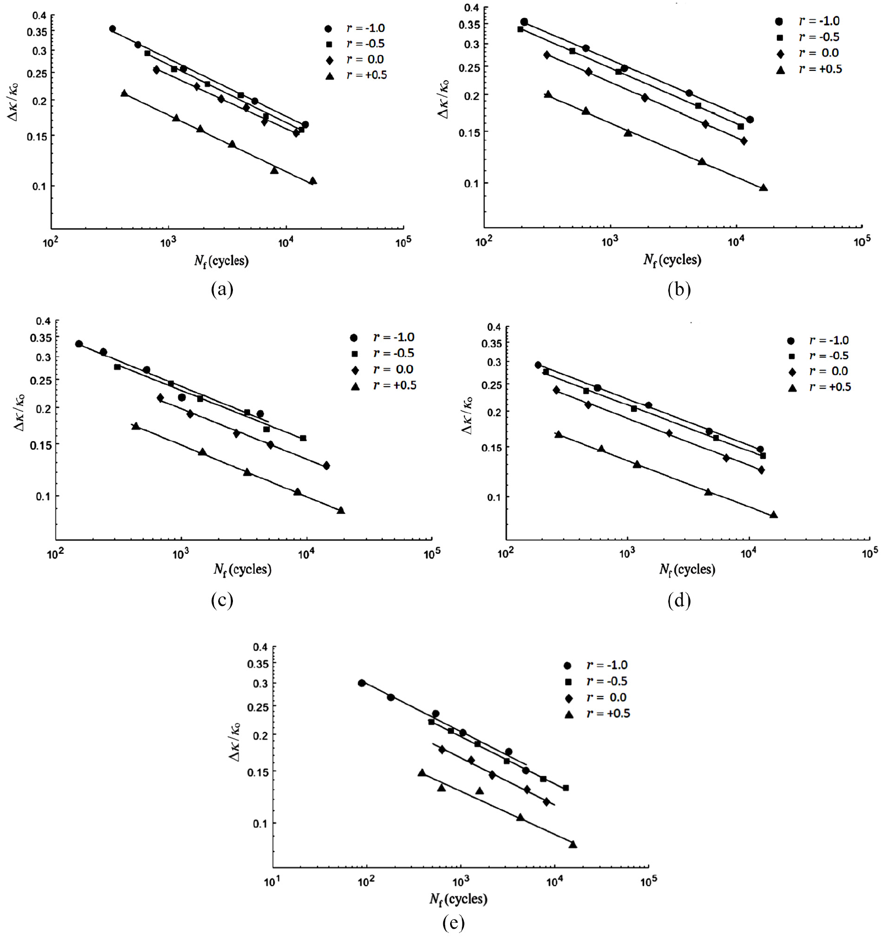
Experimental Δκ/κo-Nf relationships for AL-RHTs with d = (a) 2, (b) 4, (c) 6, (d) 8, and (e) 10 mm under cyclic bending at different r in double logarithmic coordinates.
In 2019, Lee et al. 41 suggested an empirical formulation to simulate the κ/κo–Nf relationship for Al-RHTs under cyclic bending:

where C is the material parameters which is the function of d/t, and α is the line slope in double logarithmic coordinates. In this study, equation (1) were modified to be

Note that the material parameters C and α presented below are only applicable to Al-RHTs. Figure 14 shows a 3D distribution diagram of the relationship among C, d/t, and r. The line segment is the vertical distance between the point and the regression plane. It is found that the values of log C, d/t, and 1/(1 − r) are distributed on a plane, so this paper proposes:


3D distribution diagram of log C, d/t, and 1/(1 − r).
where c1, c2, and c3 are material parameters, which can be respectively determined from Figure 14 to be −0.1021, −0.1465, and 0.1906.
From Figure 13(a) to (e), it can be found that when d is fixed, the Δκ/κo-Nf relationships in double logarithmic coordinates show almost-parallel lines distribution for different r. The slope of the parallel line is the value of α. Figure 15 demonstrates the linear relationship between α and d/t, so this article proposes:

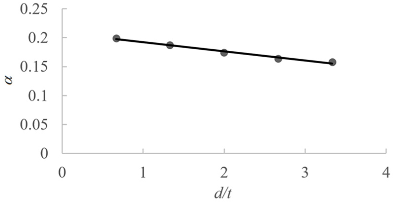
Relationship between α and d/t.
where a1 and a2 are material parameters which can be respectively determined to be −0.0159 and 0.2085. Figure 16(a) to (e) respectively display the experimental and simulated data of Δκ/κo-Nf relationships for Al-RHTs with d = 2, 4, 6, 8, and 10 mm subjected to cyclic bending at different r. It can be seen that the theoretical analysis can simulate the experimental results well.
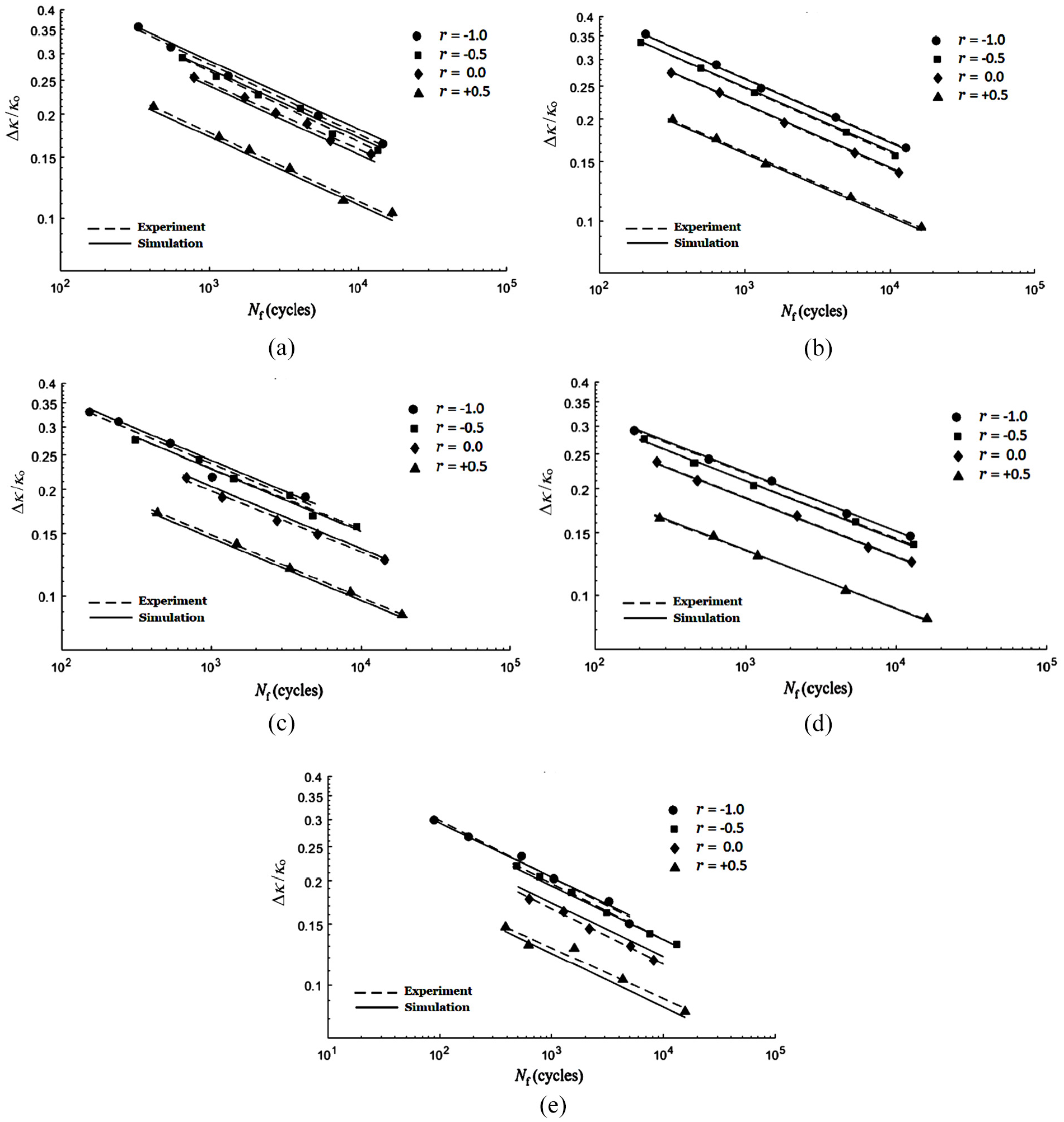
Experimental and simulated Δκ/κo-Nf relationships for AL-RHTs with d = (a) 2, (b) 4, (c) 6, (d) 8, and (e) 10 mm under cyclic bending at different r in double logarithmic coordinates.
Conclusions
This study investigates the response and failure of Al-RHTs with different d subjected to cyclic bending at different r. Based on the experimental and theoretical results, this paper can draw the following conclusions:
The experimental M-κ relationship for Al-RHTs with any d exhibits a closed and stable hysteresis loop from the first bending cycle for r = −1. However, the M-κ relationships gradually relax and become steady states after a few bending cycles for r = −0.5, 0.0, and +0.5. Because the curvature range is too small for r = 0.0 or +0.5, the deformation is within the elastic range, and the M-κ relationship demonstrates a straight line.
The experimental ΔDo/Do-κ relationship for Al-RHTs with any d exhibits an asymmetrical, ratchetting, increasing, and bow-like type as the number of bending cycles increases for r = −1. The ΔDo/Do -κ curves also show asymmetrical, ratcheting, and increasing as the number of bending cycles increases for r = −0.5. However, for larger d, it shows the shape of a tortoise shell. Because the curvature range is small for r = 0.0 or +0.5, so the deformation is in the elastic range under cyclic bending. Therefore, the increase of the ΔDo/Do becomes very slow. In addition, a larger d leads to a larger ΔDo/Do.
The experimental Δκ/κo-Nf relationship for Al-RHTs with different d subjected to cyclic bending at different r demonstrates that a higher Δκ/κo causes a lower Nf. For a fixed r, an Al-RHT with a larger d leads to a fewer Nf. For a fixed d, an Al-RHT with a larger r yields a fewer Nf. In addition, for a certain d, four almost-parallel lines correspond to four different r for the Δκ/κo-Nf relationships in double logarithmic coordinates. However, the slopes of parallel lines for five different d are different.
The empirical formulation of equation (2) was employed to simulate the Δκ/κo-Nf relationship for Al-RHTs with different d subjected to cyclic bending at different r. According to the experimental data, this paper proposed equations (3) and (4) to describe the material parameters C and α, respectively. Finally, equations (2)–(4) were used to simulate the Δκ/κo-Nf relationship for Al-RHTs with different d subjected to cyclic bending at different r. It is observed that the simulation results are in good agreement with the experimental data, as shown in Figure 16(a) to (e).
Footnotes
Handling Editor: Chenhui Liang
Declaration of conflicting interests
The author(s) declared no potential conflicts of interest with respect to the research, authorship, and/or publication of this article.
Funding
The author(s) disclosed receipt of the following financial support for the research, authorship, and/or publication of this article: This work is funded by Ministry of Science and Technology under grant MOST 110–2221–E–006–155. We are very grateful for their support.