
Abstract
This paper presents experimental study on the response of 6061-T6 aluminum alloy round-hole tubes with five different hole diameters of 2, 4, 6, 8, and 10 mm and four different diameter-to-thickness ratios of 30, 40, 50, and 60 submitted to pure bending creep and pure bending relaxation. Pure bending creep or relaxation is defined as bending the tube to the required moment or curvature and maintaining that moment or curvature for a period of time. The experimental results of pure bending creep show that the curvature increases with time. In addition, larger holding moment, diameter-to-thickness ratio, or hole diameter results in larger creep curvature. As the curvature continues to increase, the round-hole tube eventually breaks. The experimental results of pure bending relaxation show that the relaxation moment decreases sharply with time and tends to a stable value. In addition, larger holding curvature, diameter-to-thickness ratio, or hole diameter results in larger drop of the relaxation moment. Due to fixed curvature, the round-hole tube does not break. Finally, formulas proposed by the research team of Pan et al. were respectively improved to simulate the creep curvature-time relationship for pure bending creep in the initial and the secondary stages and the relaxation moment-time for pure bending relaxation. After comparing with the experimental results, it is found that theoretical analysis can reproduce the experimental results reasonably.
Keywords
Introduction
Round-hole tube (abbreviation: RHT) refers to a tube with a round hole, as shown in Figure 1. RHT is usually used for connecting components of bicycles, motorcycles, or automobiles. When RHT submits to a bending load, the bending rigidity of RHT will progressively reduce as the amount of bending increases, which is called a phenomenon of deterioration. RHT will encounter fracture when the curvature reaches a certain critical value.
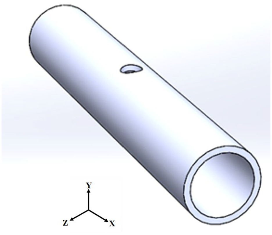
Schematic diagram of an RHT.
The study of smooth tube under bending has achieved plentiful results. In 1987, Kyriakides et al. set up a mechanical device that can perform cyclic bending tests on tubes of various materials (1020 steel, 1018 steel, 304 stainless steel, 6061-T6 aluminum alloy, and NiTi). They have carried out many experimental and theoretical studies on bending with or without internal or external pressure.1–9
Several other researchers have also published related results. Elchalakani et al. 10 determined the slenderness limits of cold-formed CHS for fully ductile section by conducting cyclic bending tests with variable amplitudes. Mathon and Liman 11 experimentally studied the pure bending collapse of cylindrical thin shells. Elchalakani and Zhao 12 investigated the cyclic bending behavior of cold-formed steel tubes with concrete filled. Yazdani and Nayebi 13 examined the damage of pipes that undergo periodic bending with a stable internal pressure. Shariati et al. 14 experimentally discussed the cyclic bending behavior of SS316L cantilevered cylindrical shells. Elchalakani et al. 15 used the strain detected in bending test to find a new ductility slender limit for the CFT structural plastic designs. Li and Wang 16 investigated the stability of single-layer cable-stiffened latticed shells submitted to earthquake motions. Chegeni et al. 17 studied the influence of the shape and depth of corrosion on the performance of a pipe that is bent under a certain internal pressure.
In 1998, Pan et al. started a series of experimental and theoretical investigations on behavior of tubes under monotonic or cyclic bending with various loading paths. Pan et al. 18 invented and constructed a new measurement equipment to measure the ovalization (change of the outer diameter divides by the outer diameter, ΔDo/Do) and curvature (κ) of tubes submitted to bending. They confirmed the function of the equipment by conducting tubes under cyclic bending. Lee et al. 19 tested the stability of 304 stainless steel tubes with four diameter-to-thickness ratios (Do/t ratios) submitted to cyclic bending. They found that the log κ-log Nb (number of cycles required to initiate buckling) relationships demonstrate four parallel lines. Lee and Pan 20 examined the pure bending creep behavior of 304 stainless steel tubes with four Do/t ratios. By modifying the Bailey-Norton law for uniaxial creep, the creep curvature-time relationships of the first two stages were simulated. Pan and Lee 21 explored the mean curvature effect on the behavior of tubes undertaken cyclic bending. Different curvature ratios of −1.0, −0.5, and 0 were considered in their experimental investigation. Chang and Pan 22 experimentally explored cyclic bending instability of tubes with four Do/t ratios. They introduced a new formula for estimating tube’s buckling life.
In 2010, Pan et al. started to experimentally and analytically investigate the behavior of tubes with a circumferential notch submitted to bending. Lee et al. 23 examined the changes of ΔDo/Do for circumferential sharp-notched tubes submitted to cyclic bending. The ΔDo/Do-N (number of cycles) curve was identified into three different growing stages. Later, Lee 24 investigated cyclic bending response of circumferentially sharp grooved tubes with different depths. A theoretical formula for estimating Nb was proposed. Thereafter, Lee et al. 25 examined the stability of circumferential sharp-notched 304 stainless steel tubes submitted to cyclic bending at different curvature rates (viscoplastic response). They employed three curvature rates of 0.35, 0.035, and 0.0035 m−1/s to demonstrate the viscoplastic response. Lee et al. 26 inspected the pure bending creep behavior and pure bending relaxation behavior of tubes with a circumferential sharp notch. The formula proposed by Lee and Pan 20 was improved for describing the creep curvature-time and relaxation moment-time relationships. Chung et al. 27 investigated the cyclic bending collapse of circumferential sharp-notched 6061-T6 aluminum alloy tubes. The κ-Nb relationship exhibited considerable differences from that discovered by Lee 24 in circumferential sharp-notched 304 stainless steel tubes subjected to cyclic bending.
In 2016, Lee et al. 28 explored the mechanical behavior of local sharp-cut 6061-T6 aluminum alloy tubes subjected to cyclic bending. In their study, the ANSYS was employed to simulate the ΔDo/Do-κ and M (moment)-κ relationships. After that, Lee et al. 29 researched the failure of local sharp-grooved 304 stainless steel tubes submitted to cyclic bending. The M-κ relationships were very similar to that obtained by Lee et al. 25 ; but, the contours of the ΔDo/Do-κ relationships were completely different. Lee et al. 30 inspected the deterioration and failure of local sharp-dented 6061-T6 aluminum alloys tubes submitted to cyclic bending. The dent was created by contacting the mold on the tube’s surface. In addition, a theoretical formula was put forward to express the κ-Nf (number of cycles required to initiate failure) relationship.
In this study, the response of 6061-T6 aluminum alloy round-hole tubes (abbreviation: Al-RHTs) with different hole diameters of 2, 4, 6, 8, and 10 mm, and different diameter-to-thickness ratios of 30, 40, 50, and 60 submitted to pure bending creep and pure bending relaxation are examined. In the experimental part, a bending machine was employed to perform relative experiments on Al-RHTs. The magnitudes of M and κ were obtained by the measuring devices on the machine. Additionally, time (
Experiment
Experimental equipment
The experiments executed by a tube-bending machine. Figure 2(a) and (b) respectively show a schematic diagram and a picture of the machine. It was designed to perform a pure bending test (four-point bending test), which can apply monotonic and cyclic bending. The machine consists of two rotating sprockets, placed symmetrically on two support beams. Two sprockets support two rollers, which apply point loads at each end of the tube. The chains run around these sprockets and are connected to two hydraulic cylinders and load cells to form a closed loop. Once the top or bottom cylinder is contracted, the sprocket will rotate to achieve pure bending of the tube. The load transferred to the tube is the moment formed by the concentrated load of the two rollers. For a detailed description of the tube-bending machine, please refer to the following papers (Lee et al., 19 Lee and Pan, 20 and Pan and Lee 21 ).

2(a) Schematic diagram of the tube-bending machine and 2(b) picture of the tube-bending machine.
Figure 3(a) and (b) respectively depict a schematic diagram and a picture of an apparatus to measure the ΔDo/Do and κ of the tube invented by Pan et al. 18 When the tube is bent, the two side-inclinometers in the device is able to detect the tube’s angle changes. The κ can be easily calculated according to angle changes. In addition, the central part of the equipment can be used to monitor the change in the diameter of the tube cross section using a magnetic detector. Thus, the ΔDo/Do can be measured. For a detailed explanation of the apparatus, please refer to the Pan et al. 18 study.

3(a) Schematic diagram of the measurement apparatus and 3(b) picture of the measurement apparatus.
Materials and specimens
The chemical composition by weight percentage of the 6061-T6 aluminum alloy is 0.916% Mg, 0.733% Si, 0.293% Cu, 0.268% Ti, 0.256% Fe, 0.132% Mn, 0.0983% Zn, 0.0682% Cr, and the remaining part Al. The mechanical properties are ultimate tensile stress (σu) = 320 MPa, yield stress (σo) = 283 MPa, and percent elongation (%εf) = 13%.
Smooth 6061-T6 aluminum alloy tubes with Do = 36.0 mm and t = 3.0 mm were machined on the outer surface to acquire the desired Do/t ratios of 30, 40, 50, and 60, as shown in Figure 4. However, the inner radius (29.0 mm) of all tested Al-RHTs was unchanged. Next, the tube with every Do/t ratio was drilled again to obtain the Al-RHT with the required hole diameter d. In this study, five d values were considered, 2, 4, 6, 8, and 10 mm.

Schematic diagram of tubes with Do/t ratios of 30, 40, 50, and 60.
Because the hole is local, the hole direction ϕ (Figure 5) may also affect the RHT’s behavior. Since the degradation and failure of the RHT undergoing bending is the most severe when the bending moment direction (z direction) is perpendicular to the ϕ. Therefore, this study only considers ϕ = 0° (y direction).

Schematic diagram of the cross-section of the RHT with a round-hole direction at ϕ.
Test procedures
The experiment includes pure bending creep (bend the tube to the required M and hold that M for a period of time) and pure bending relaxation (bend the tube to the required κ and hold that κ for a period of time). For each Al-RHT with certain Do/t and d, different M and κ were respectively held for pure bending creep and pure bending relaxation. The M and κ were measured and controlled by the related equipment. Furthermore, the
Experimental results, simulated results, and discussion
Experimental response of Al-RHTs under pure bending
Figure 6 shows the experimental M-κ curves for Al-RHTs with different Do/t and different d subjected to pure bending. For each Do/t ratio, five d values, 2, 4, 6, 8, and 10 mm, were tested. It can be seen that the linear M-κ relationship is observed when the deformation is in the elastic range. Once the deformation is in the plastic range, the M-κ relationship becomes nonlinear. It can also be observed that the RHT with a larger Do/t ratio has a smaller t. Therefore, the M-κ curve shows a lower M value. In addition, for each Do/t ratio, the M-κ curves are similar for different d. However, d = 2 mm has the largest breaking curvature and d = 10 mm has shortest breaking curvature. The breaking points are denoted as “*,”“×□”“▴,”“♦” and “■” for d = 2, 4, 6, 8 and 10 mm, respectively. Subsequently, the held moments of Al-RHTs with different Do/t and different d for pure bending creep and the held curvatures of Al-RHTs with different Do/t and different d for pure bending relaxation were according to the M-κ curves in Figure 6.

Experimental M-κ curves for Al-RHTs with different Do/t and different d subjected to pure bending.
Experimental response of Al-RHTs under pure bending creep
Figure 7 demonstrates the experimental κ–

Experimental κ–
Next, We focus on the pure bending creep part from the creep starting point “•” to the creep rupture point “×” in Figure 7. Figure 8 depicts the κc–
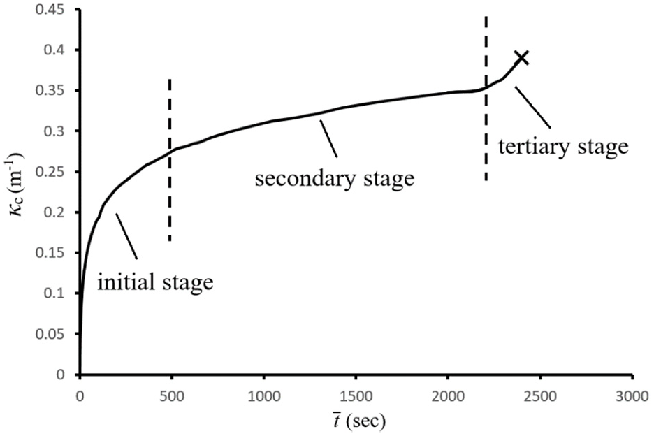
Experimental κc–
Theoretical simulation for Al-RHTs under pure bending creep
In 2002, Lee and Pan
20
tested smooth 304 stainless steel tubes with different Do/t ratios submitted to pure bending creep. They proposed a theoretical formulation to describe the κc–

in which M is the held moment, C, m1, and n1 are material parameters. In their study, m1 and n1 were respectively determined to be 5.70 and 0.53 and C was a function of the Do/t ratio. In 2014, Lee et al.
26
studied the κc–
In this study, the κc–

Experimental and simulated κc–
Figure 10(a) to (e) respectively indicate the experimental κc–

Experimental and simulated κc–

Experimental and simulated κc–

Experimental and simulated κc–

Experimental and simulated κc–
Amounts of C for different Do/t ratios and different d/t.

When we consider the lnC and d/t relationship, four straight lines for Do/t = 30, 40, 50, and 60 are observed (see Figure 14). Thus, the parameter C can be proposed as

where c1 and c2 are material parameters which are related to Do/t ratio. The amounts of c1 and c2 can be determined in Figure 14.

Relationship between lnC and d/t.
From Figure 15(a) and (b), linear relationships of lnc1-lnDo/t and lnc2-lnDo/t are respectively observed. Therefore, parameters c1 and c2 are respectively proposed to be

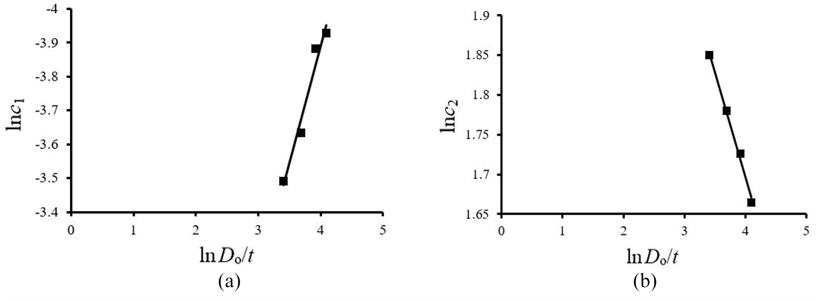
(a) Relationship between lnc1 and lnDo/t, and (b) relationship between lnc2 and lnDo/t.
and

where α1, α2, α3, and α4 are material parameters which are respectively determined from Figure 15(a) and (b) to be 0.679, −1.172, −0.263, and 2.749. The solid lines in Figure 10(a) to (e) respectively indicate the simulated κc–
Experimental response of Al-RHTs under pure bending relaxation
Figure 16 demonstrates a typical M–
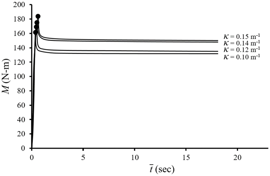
Experimental M–
Theoretical simulation for Al-RHTs under pure bending relaxation
In 2014, Lee et al.
26
tested circumferential sharp-notched 304 stainless steel tubes submitted to pure bending relaxation. They proposed a theoretical formula to describe the relationship between relaxation moment (Mr) and

where κ is the held curvature, R, m2, and n2 are material parameters. In their study, m2 and n2 were respectively determined to be 0.15 and −0.07 and the parameter R was proposed as a function of notch depths for circumferential sharp-notched 304 stainless steel tubes.
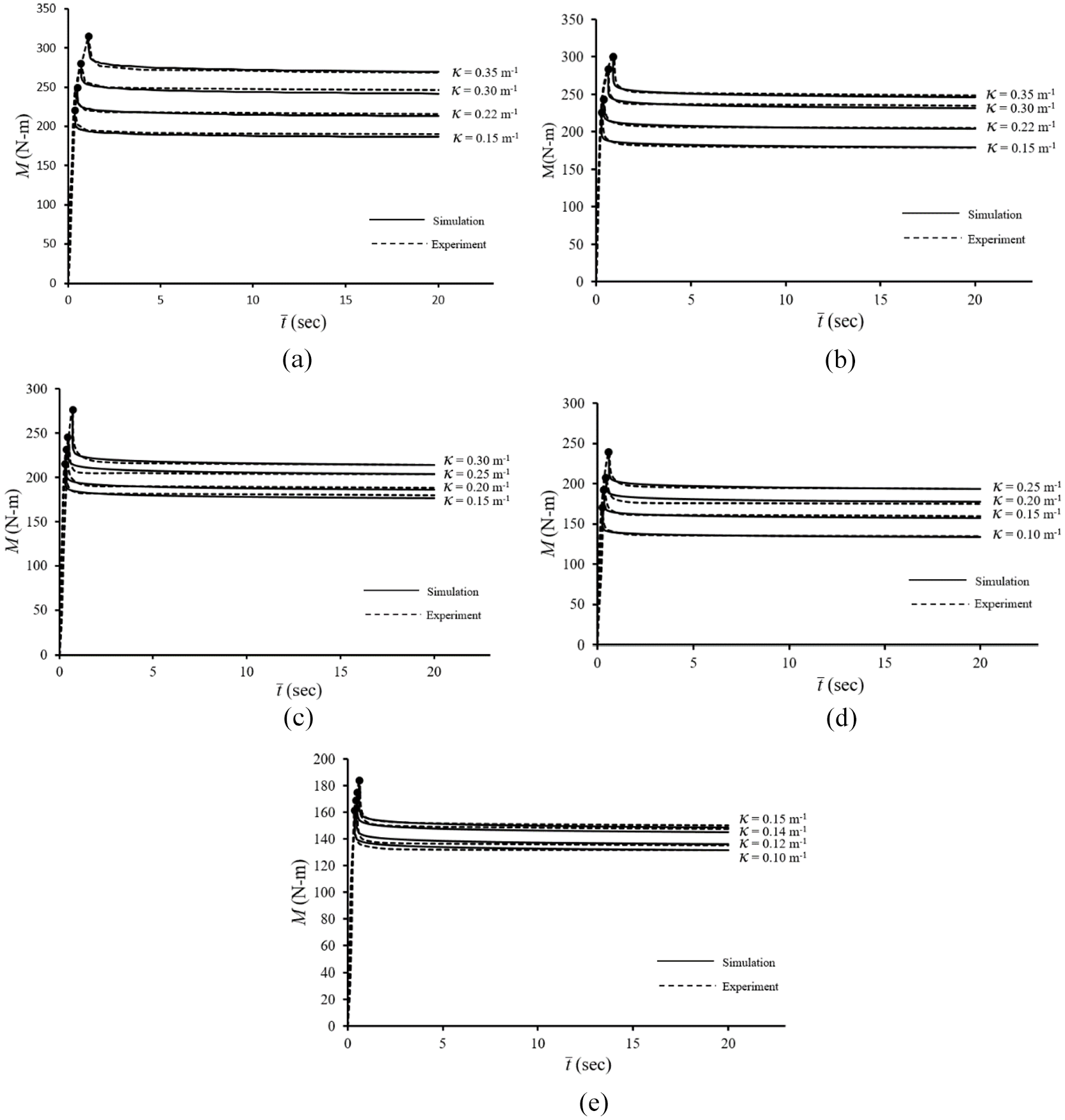
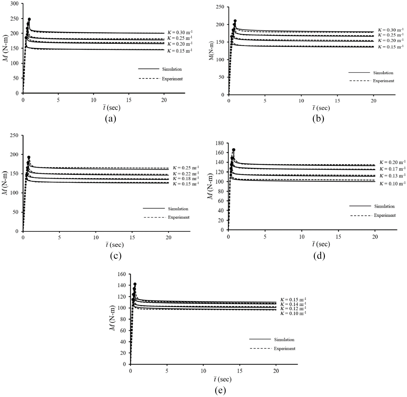
In this study, the Mr–

Experimental M–
Figure 18(a) to (e) respectively indicate the experimental M–

Experimental M–
Experimental M–

Experimental M–
Experimental M–
Amounts of R for different Do/t rations and different d/t.

When we consider the R1/3-d/t relationship, four straight lines for Do/t = 30, 40, 50, and 60 are observed (see Figure 22). Therefore, parameter R is proposed to be


Relationship between R1/3 and d/t.
where r1 and r2 are material parameters which are related to Do/t ratio.
From Figure 23(a) and (b), linear relationships of lnr1-lnDo/t and lnr2-lnDo/t are observed. Therefore, parameters r1 and r2 are respectively proposed to be


(a) Relationship between lnr1 and lnDo/t, and (b) relationship between lnr2 and lnDo/t.
and

where β1, β2, β3, and β4 are material parameters which are respectively determined from Figure 23(a) and (b) to be −0.750, −0.459, −0.199, and 2.759. Figure 18(a) to (e) respectively indicate the simulated Mr–
Conclusions
This paper presents the experimental and theoretical research on the response of Al-RHTs with different Do/t ratios and different d submitted to pure bending creep and pure bending relaxation. Based on experimental and theoretical results, this paper draws the following important conclusions:
It is seen from the M-κ curves for monotonic bending that once the deformation is in the plastic range, the M-κ relationship becomes nonlinear. It can also be observed that the larger the Do/t ratio, the smaller the tube wall thickness. Therefore, a lower M value is found. In addition, for each Do/t ratio, the M-κ curves are similar for different d. However, a smaller d leads to a larger breaking curvature.
It is found from pure bending creep that once the pure bending creep begins, the curvature increases quickly. In addition, the κc–
It is observed from pure bending relaxation that once the relaxation begins, the moment drops sharply and gradually becomes a stable value. In addition, the Mr–
The theoretical formula proposed by Lee and Pan
20
was employed for simulating the κc–
Footnotes
Handling Editor: Chenhui Liang
Declaration of conflicting interests
The author(s) declared no potential conflicts of interest with respect to the research, authorship, and/or publication of this article.
Funding
The author(s) disclosed receipt of the following financial support for the research, authorship, and/or publication of this article: This work is funded by Ministry of Science and Technology under grant MOST 108-2221-E-006-183. We are very grateful for their support.