
Abstract
This paper proposes a novel state estimation based permanent magnet synchronous motor (PMSM) control method for electric vehicle (EV) driving. Firstly, a state feedback decoupling control with disturbance feed-forward (SFDCDF) is described. As motor angular speed and rotary angle are key information for the proposed control algorithm and park’s transformation, a novel observer based angular speed estimator (OBASE) is proposed for angular speed estimation. Moreover, an extended Kalman filter (EKF) based rotary angle estimator (EBRAE) is used for rotary angle estimation with information of the estimated angular speed. The convergence of angular speed estimation is proven through Lyapunov stability theory. Simulation results also indicate that the proposed algorithms can control PMSM torque, current, and angular speed to accurately follow reference values without severe fluctuation. In addition, in order to provide SFDCDF with load torque information, the OBASE is slightly modified to work as a vehicle load estimator (VLE) so PMSM responds more rapidly and speed fluctuates more slightly when the load suddenly changes. Then a series of hardware in the loop (HIL) simulations are carried out. Results indicate that the proposed control strategy can precisely estimate PMSM’s angular speed and rotor angle. Also, it can improve the driving performance of PMSM used on EVs.
Keywords
Introduction
Permanent magnet synchronous motor (PMSM) is widely used in various areas. Its small volume, light weight, high efficiency, high power factor, fast response, wide speed range, and good accuracy make it replace DC motor to be broadly used in electric vehicles (EV) including pure electric vehicles (PEV) as well as hybrid electric vehicles (HEV). Many articles1–8 have researched on electric motors control especially on sensorless control. However, few of them focuses on applications on EVs. EVs usually possess characteristics of large range of and high changing frequency of speed and load torque. In some active safety systems, such as antilock braking system (ABS), traction control system (TCS), and electric stability program (ESP), accurate speed control is required. 1 However Sun and Mills, 2 focuses only on high-speed system. Foo and Rahman3,4 focus only on low-speed drive. Sivaprakasam and Manigandan 5 focuses on low load torque (maximum 5 N m) system. Shah et al. 6 assumes the load torque as constant value.
In this paper, we are interested in replacing sensors that measure rotary position, speed and load torque by states estimators in non-salient PMSM control focusing on application on EVs. Traditionally, extended Kalman filter (EKF) is widely used as state estimator of the machines. 7 However, it is a stochastic control algorithm which gives recursive optimum state estimation using terminal signals that may be interfered by noise. Foo and Rahman3,4 propose a sliding mode stator flux observer to achieve sensorless motor drive at very low speed without signal injection. They briefly introduce the way of injecting high frequency signals of voltages or current. Uddin 8 describes a fuzzy logic controller for speed control of interior permanent magnet (IPM) motor. The problem is that fuzzy logic is an experience-based control strategy. Its behaviors heavily depend on experiment data which is difficult to obtain for EV applications since driving cycles are various with drivers. Sun et al. 9 introduces a maximum torque per ampere (MTPA) control based on virtual signal injection. It is more advanced than real signal injection because it is parameter independent in tracking MTPA points. Moreover, it is robust to current/voltage harmonics and motor torque disturbances. Inoue et al. 10 further describes a mathematical model for MTPA control. As the model is in stator flux linkage synchronous frame it is of simplicity of flux-weakening control law and of applicability to various motors. However, MTPA control generates d-axis current, consequently the whole efficiency of the motor decreases so it is not commonly used in EVs whose main features are high efficiency and low emission.
From the respect of parameter estimation, papers11–14 discuss many parameter estimation methods. Patre et al. 11 proposes a composite adaptive control law driven by tracking and prediction errors with a fixed adaptation gain. Adetola and Guay 12 presents how finite-time identification procedure can be used to improve performance of adaptive control systems. Sahlholm and Henrik Johansson 13 proposes a road gradient estimation method using multiple measurement runs. All these methods have problems either of needing many sensors or of possible instability and infinite growth.14,15 Refs14–16 propose a regression-based method containing a sliding mode type term to ensure fast parameter convergence. However, the regression term is only useful for time-invariant systems or systems with parameters changing at low frequency. As rotor angular speed usually varies rapidly it does not suite sensorless motor control as well.
From the respect of EVs, considerable literatures16–28 make contribution to EV energy management and dynamics control. Barsali et al.16,17 present a generator ON/OFF algorithm with the goal to minimize fuel consumption for series HEV. Chen et al. 18 proposes an optimal management algorithm using quadratic programming and simulated annealing method together. Nonetheless, very few of them focuses on driving control. Peng et al. 22 describes a neural network PID controller for EV torque control. Yoshimura and Fujimoto 23 proposes a traction control strategy for EVs. But they mainly focus on vehicle dynamics and wheel dynamics.29–31 have made great contribution to motor control for EVs in terms of utilizing binary search, phase-locked loop, and finite position set.
This paper proposes a series of algorithms to estimate parameters, to observe states, and to control PMSM to drive EVs. Firstly, a non-salient PMSM model is described and validated through comparing with a Simscape model in the second section. Then the controller is designed in the third section. The algorithms include a state feedback decoupling control with disturbance feed-forward (SFDCDF), a novel observer based angular speed estimation (OBASE), an improved EKF based rotary angle estimation (EBRAE), and a vehicle load estimation (VLE). Then convergence of the observer-based parameter estimation is proven by Lyapunov stability theory. Software simulations are carried out to test the performance of each part separately. In the next section, an ETAS based Hardware in the loop (HIL) test bench is introduced. The real physical component of the loop is the controller in which algorithms are coded by C language. Then tests are carried out to analyze the performance of all algorithms working together. Finally, a conclusion is given in the final section. The main contribution of this paper lies in the effort of innovatively trying to combine three estimators into the motor control specifically for electric vehicles.
System formulation
D-q coordinate model
According to Ciabattoni et al., 7 a non-salient three phase PMSM model can be written in rotating (d-q) coordinate

where
It is known that d-q coordinate is rotating with rotor, but space coordinate of real three phase voltage and current is static. The relationship between d-q coordinate variables and static coordinate variables is

where

where
With the Park’s transformation, the real three phase voltage and current can be easily transformed into d-q voltage and current if rotor angle is known. Here considers

where
Model validation
The model is computed in MATLAB/Simulink environment and is compared with professional electric power simulator “Simscape” to verify its validity. In the simulation, the reference speed is a step signal which steps from 0 to 100 rpm at 0.1 s. In addition, to further compare the two models’ response to torque disturbance, a 50 N m load torque is introduced at 3 s.
Figure 1 shows the results of validation under vector control assuming all parameters are known. Figure 1(a) indicates that with the reference speed stepping from 0 to 100 rpm at 0.1 s, the rotor angular speed of Simscape model and the model described by (1)–(3) increases to 100 rpm within 1.5 s almost together. Only from the enlarged view can the discrepancy be recognized. Then the speed tends to be steady until disturbance occurs. From Figure 1(b), the torque of Simscape model fluctuates more severely. This is due to taking more electromagnetic interference into account. The q-axis currents of both models, as shown in Figure 1(c), have similar trend. Both d-axis currents keep close to zero because the reference d-axis current is set as zero to improve the motor efficiency. Then the output torque is approximately proportional to q-axis current (see (1)). The three phase currents in Figure 1(d) and (e) have the same shape but the vibration of Simscape model is more intense. Furthermore, both models respond to torque disturbance in exactly the same way. Consequently, the model described through (1)–(3) is considered valid in this paper.
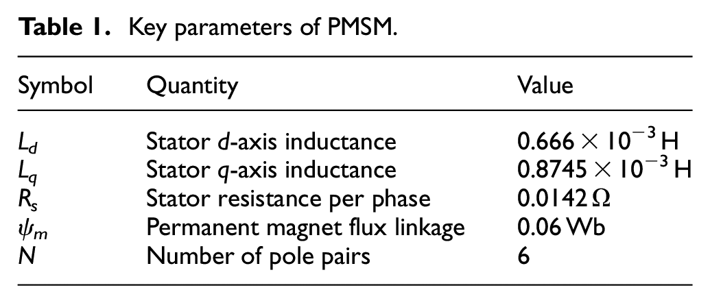
Remark 1: Motors need driving system to operate. In this comparison, every detail is the same but motor models. So, any discrepancy of simulation results is caused by motor models only. Some key parameters of the PMSM provided by Simscape are given in Table 1.29–31

Test on model (1)–(3) compared with commercial electric power simulator: (a) angular speed, (b) output torque, (c) d-q current, (d) three phase current of Simscape model, and (e) three phase current of model in paper.
Key parameters of PMSM.
Controller design
State feedback decoupling control with disturbance feed-forward (SFDCDF)
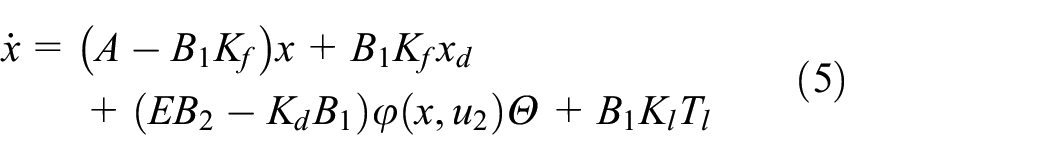
The system described by (3) has similar form of (1) in Na 14 but its nonlinear item only exists in output. Therefore, if all states are assumed measurable the law of SFDCDF can be given as

where
If
where

The structure of state feedback decoupling control.
The simulation comparison between the SFDCDF and non-SFDCDF, in Figure 3, shows that the fluctuation of output torque and three phase currents are efficiently reduced. The amplitude of fluctuation of speed and torque that are caused by disturbance torque is significantly compressed. The output torque of SFDCDF responds even faster than reference torque provided by speed PID controller.
Remark 2: Angular speed and load torque are just assumed known, so the rest of the section focuses on how to obtain the information with estimation. Furthermore, state

Test on the influence of feedback decoupling control on fluctuation elimination: (a) angular speed, (b) output torque, and (b) three phase current.
Observer based angular speed estimation (OBASE)
In real life, there are two approaches to obtain the value of

where
Combine (3) and (6), the error dynamics

where

where
Equation (6) has similar form of (3) in Mahyuddin et al. 15 but the estimation proposed in Mahyuddin et al. 15 does not suit the angular speed estimation since the algorithm in Mahyuddin et al. 15 introduces a low pass filter to gain constant parameters or parameters that change very slowly. Whereas, rotor’s angular speed changes every second during running. By removing its regression correction item which contains the low pass filter, and adding a derivative item the estimator is proposed as
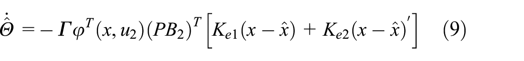
where
Figure 4 gives the structure of the observer-based estimator. The parameter estimation mainly depends on the error between the observed states and the measured states. As the derivative item is introduced the convergence speed increases, so the estimation algorithm is more suitable for rapidly changing parameters.

The structure of observer-based estimation.
Estimation convergence
To analyze the stability and convergence, the considered Lyapunov function is

As

Then consider the first and the third items of (11), we have

Then, consider the second, the fifth, and the sixth items of (11). As matrices
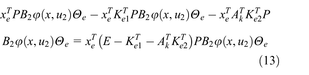
where
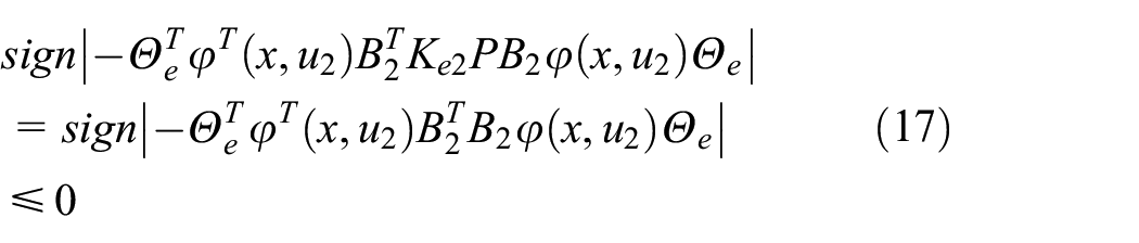
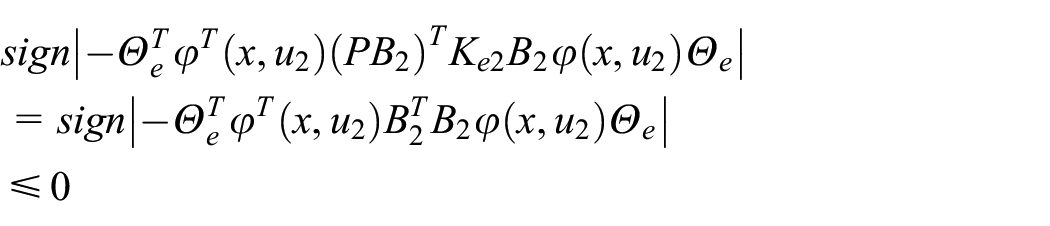
As signs of

Furthermore, consider the forth, the eighth, and the ninth items of (11). A similar expression can be obtained as
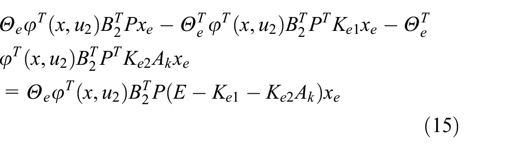
Also, (15) is kept zero by setting

It is obvious that (14) and (16) are equivalent. And they are achievable because
Consider the seventh item of (11), we have
Similar results can be obtained when considering the last item of (11).
According to the analysis above,
Simulations are carried out to further evaluate the performance of angular speed estimation. Results are shown in Figure 5. Even though there is error between the real and estimated angular speed, as Figure 5(b) shows, it is bounded and convergent to zero. With the estimation, the real speed is controlled closely to reference as well.

Test on the performance of observer based angular speed estimation: (a) angular speed and (b) angular speed error.
EKF based rotor angle estimation (EBRAE)
Direct integral to angular speed may cause huge error in rotor angle so an EKF based estimation is introduced to provide Park’s transformation with angle information. Firstly, the wheel dynamics is

where
If let state

The system is unobservable so EKF is not able to directly estimate the rotor angle. To obtain precise angle information, here applies angular speed’s integral as knowable state so the EKF based estimator is as Figure 6. A simulation comparison is carried out to test the performance of the proposed estimation. Results in Figure 7 show that the EKF based estimator has much smaller error than the sole integral of estimated angular speed.

Structure of EKF based rotor angle estimator.

Test on EKF based rotor angle estimator: (a) rotor angle, (b) error of the EKF based estimation, and (c) error of speed integral.
Vehicle load estimation (VLE)
As described previously, vehicles’ working condition is various. Any kind of load will be transferred to driving system. If the information of load torque can be obtained in advance the response of driving motor will be more rapid and the speed shock will be eliminated. So the considered vehicle dynamics is

where
As (19) refers to Mahyuddin et al.
15
the model validation will not be described here. Furthermore, (19) has the form of (3) if

where
Meanwhile, the estimator is

where
Then the whole structure of load torque estimator is shown in Figure 8. The persistent excitation is guaranteed by the constant estimation of angular speed. Then the load torque is obtained through
Remark 3:

Structure of load torque estimator.
The performance is tested by simulation. As the vehicle mass and vicious coefficient are not changeable during driving in most cases. Here sets them as fixed value. Key parameters of the vehicle are shown in Table 2. The road gradient steps from 0 to 0.1745 rad at 1.5 s, then from 0.1745 to 0.5236 rad at 3.5 s. And the driving force is assumed as a sine signal with bias of 1000 N and amplitude of 500 N. The results of torque load are shown in Figure 9. The estimated value keeps close to real value. The biggest error remains less than 8 N m, which is not beyond controller’s adjusting ability, so the algorithm is valid.
Key parameters of EV and road.


Test on load torque estimator.
HIL test
HIL platform
The philosophy of HIL simulation is based on traditional pure software simulation. In HIL simulation, some virtual models are replaced by real hardware. The real components interact with virtual models in real time to create a HIL simulation. In the case of this paper, three phase current of PMSM is the output of virtual components. Signals transmit to controller via CAN (control area network) bus. Then entire process of observation, estimation, and control is computed in the microcontroller. Then three phase voltage signals are sent back to ETAS HIL RTPC as input of models. The configuration of HIL system is shown in Figure 10.

Structure of HIL system.
In the HIL simulation conducted in this paper, only a real “Freescale” microcontroller is available. Systems like vehicle dynamics, powertrain, battery, etc. are simulated by models. The host PC communicates with ETAS HIL RTPC through Ethernet. Models can be built in the host PC and downloaded to ETAS using LABCAR Integration Platform (IP). Host PC can also manage the experiment like running, stopping simulation as well as configuring hardware boards using IP and LABCAR Experiment Environment (EE). Models run in real time in ETAS system. Through a CAN bus they transmit information to the real controller in which the proposed algorithms are coded using C language. And the real controller outputs control signals to models through ordinary I/O ports. So, the whole system forms a closed loop in which models use control signal from real controller to operate correctly and the real controller uses models’ computation results as inputs. The test bench of the HIL simulation platform is shown in Figure 11.

The bench of HIL simulation platform.
Virtual models
Virtual models in the HIL system include PMSM, battery, longitudinal vehicle dynamics, wheel rotation, wheel slip, and tire-road. In the following, battery model, wheel slip model, and tire-road are going to be described. Other models like PMSM, wheel rotation, longitudinal vehicle dynamics have been respectively introduced by (1), (19), and (21).
(1) Battery model. According to Zhang, 28 there are three commonly used electrical battery models. The one with one resistance and one RC combination, shown in Figure 12, is chosen in this paper due to considering both accuracy and simplicity. Input of the model is current, and output is voltage. The components of the model are:
OCV is the open circuit voltage;
R s1 and Rs2 are the resistances;
C s is the capacity.

Electrical battery model with one resistance and one RC combination.
The OCV has a reciprocal relationship with charge defined by

where
(2) Wheel slip model. If
(3) Tire-road model. The friction between tire and road is the main source of traction and brake force that drives vehicles. The most widely used tire-road models include magic formula, uniformed tire model, etc. In this paper, the model described in Wei and Xuexun 1 is chosen. And here assumes that vertical load on each wheel does not change at any time. Then the model is given as

where
Results and analysis
This test focuses on comprehensive capacity of SFDCFD control and performance of parameter estimation. PMSMs are applied as hub motors driving four wheels respectively. Most parameters of the PMSM and the vehicle keep the same as in Tables 1 and 2 with only a few modifications. Firstly, the permanent magnet flux linkage is set to 0.12 Wb to provide larger torque with lower current. Then inertial of rotor is set to 27 kg m2 considering the affection of mass of vehicle body. In addition, road gradient just steps from 0 to 0.1745 rad at 20 s. Reference angular speed steps from 0 to 885 rpm which can be interpreted as 100 km/h if wheel radius is 0.3 m. And parameters of controller and estimators are given in Table 3 after prudently tuning. The results are shown in Figures 13 and 14. As Figure 13(a) illustrates, when road gradient changes the angular speed of non-SFDCDF fluctuates with larger amplitude, which means that SFDCDF enhances the system’s robustness against disturbance. From Figure 13(b), the error also indicates the fact that speed is controlled precisely because the maximum error is 1 rpm when disturbance exist and the error is close to zero in other situation. Both Figure 13(c) and (d) indicate that rotor angle is estimated with error that is close to zero. Figure 13(e) explains that the reason why the angular speed of non-SFDCDF is influenced by load disturbance more seriously is because its output torque reacts more slowly. Figure 13(f) is just to show that the load torque can be accurately estimated. Besides the mechanical results in Figure 13, electric results in Figure 14 also confirm the benefit of SFDCDF. Figure 14(c) the steady state error of d-q currents under SFDCDF is kept to zero, whereas non-SFDCDF has apparent steady sate error even though it has smaller error at a certain stage. In terms of computation consumption, in each loop it takes about five times more time for the proposed method (set to 10 ms) than conventional method (set to 2 ms). As the results show that the control performance is not adversely affected by added observers with the set sampling time, it is considered that the computational load can be handled by the controller.

Mechanical results of HIL simulation test on proposed controller and estimators: (a) angular speed, (b) speed error, (c) rotor angle, (d) angle error, (e) output torque, and (f) load torque

Electric results of HIL simulation test on proposed controller and estimators: (a) d-q coordinate current, (b) d-q coordinate current, and (c) current error.
Key parameters of EV and road.

Conclusion
In this paper, a relatively complete non-sensor PMSM control strategy for EV, which includes a SFDCDF, an OBASE, an EBRAE, and a VLE, has been proposed. Firstly, the SFDCDF contains a decoupling item to eliminate the adversely mutual impact of two system states. Furthermore, the disturbance feed-forward item can assist the system to react to disturbance faster. To provide the controller with enough information, a novel OBASE is proposed. The two main parts, observer and estimator, are designed respectively. The convergence of the OBASE is theoretically proven by Lyapunov steady theory. In addition, an EBRAE is used instead of integration of angular speed to obtain rotor angle.And the OBASE is reused as a VLE with slightly adjustment to gain vehicle load information. In each part, simulations are carried out to prove each algorithm can operate appropriately.
In the fourth section, all proposed algorithms are coded in a “Freescale” controller for a HIL test. Firstly, the HIL system is briefly introduced. Then other necessary models like battery model, wheel slip model and tire-road model, are described respectively. The test results are presented and analyzed to evaluate the performance of the whole system. Primarily, all algorithms work together stably. This simultaneously certificates the effectiveness of coding. However, one defect of this research is that the only hardware in the loop is the controller. The test would be more persuasive if more real physical parts, such as real motor and real battery, are involved in.
To sum up, in PMSM control, measurement of mechanical states is replaced and estimated by easier, more rapid and more reliable measurement of electric states like currents. All algorithms proposed in this paper can control the PMSM to drive an EV stably and effectively. However, more work like adding more real hardware in the system need to be done in the future.
Footnotes
Appendix
Handling Editor: Chenhui Liang
Declaration of conflicting interests
The author declared no potential conflicts of interest with respect to the research, authorship, and/or publication of this article.
Funding
The author received no financial support for the research, authorship, and/or publication of this article.