
Abstract
Friction stir welding is an environmentally friendly process of joining due to the non-usage of flux, or any shield gas. Therefore, this article proposes an experimental and thermal investigation with optimization technique for studying the process of FSW on nylon 6A or polycaprolactam polymer composite plates. Specifically, the influence of input operating process parameters such as tool rotational speed (TRS), feed rate, and pitch values on the output response parameters like ultimate tensile strength (UTS), and hardness of welded joints is examined. In addition, L27 orthogonal array of Taguchi approach is employed for the optimization of design experiments of FSW parameters. The experimental setup is carried out with various process parameter combinations like 500, 1000, and 1500 rpm as TRS, 30, 40, and 50 mm as feed rate by varying the pitch values as 1, 2, and 3 mm. Further, the analysis of variance (ANOVA) also employed for finding the significant parameters of input process using the regression analysis equations. Finally, microstructural analysis is used to assess the mixing or dispersing uniformity of composites effectively. The experimental and optimum FSW parameters for maximum UTS are obtained at a feed rate of 30 mm/min, tool pitch of 3 mm, and the TRS of 500 rpm.
Introduction
For improving production efficiency and reducing the costs with lower environmental effect in electronic, automobile, and aerospace devices, the benefits of good corrosion resistance, high specific strength, processing ability, and excellent design freedom have the potential in polymers and polymer matrix composites (PMCs).1,2 The joining technology of welding techniques like adhesive bonding and mechanical fastening are required for the large and complex parts fabrication.
3
At the bonding region, stress concentration is appeared easily for reducing the joint reliability by manipulating the mechanical fastening that results in the increasing of lightweight design deterioration. Relatively, adhesive bonding is mature that requires long processing cycle. However, humidity resistance, impact resistance, and fatigue resistance are not enough for reducing joint property. The welding process is the best joining technique that includes different kinds, such as electric resistance welding, linear vibration welding, hot plate welding, FSW, and ultrasonic welding, etc.
3
Three different processes include in these welding techniques: (a) a layer of molten material formation to be joined on the surfaces, (b) upsetting forms the bonding, and (c) the stage pressure and molten material cools should have to maintain for preventing the forming of voids within the weld zone.
4
Spot welding is performed mainly by ultrasonic welding but need to spend higher costs on tools and machines and more time is required for preparation. For forming the proper joint at a terribly slow rate, a
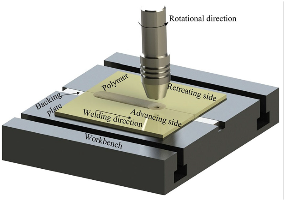
Schematic diagram of FSW.
As the polymers includes the molecules with various chain lengths and not included definite melting point instead of melting ranges, FSW is not a solid-state process and its thermoplastic polymers distinct from metal. 6 Some shorter chains of FSW may reach to the melting point while applying FSW/P to polymers. Whereas longer chains are in solid state. For thermoplastic polymers, FSW is implemented in 1997 and seldom works report due to the immaturity.
Nelson et al., 7 has improved different tools to combine thermoplastic polymers. In 2005, and especially after 2009, the systematical research has started on the FSW of thermoplastic polymers. 8 The joining of PMCs and thermoplastic polymers has realized by FSW. These polymer composites are 20% carbon fiber-reinforced PP composite, 9 30% glasses fiber reinforced PP composite, 10 Polyethylene Terephthalate (PET), 11 Polycaprolactam (nylon 6), 12 Polymethyl Methacrylate (PMMA), 13 Acrylonitrile Butadiene Styrene (ABS), 14 Poly Carbonate (PC), 15 Poly Propylene (PP), 16 and different grades of Polyethylene (PE). 17 Raza et al. 18 was used a specific developed tool with a grooved conical pin and a concave shoulder based on high-density polyethylene (HDPE) sheet friction stir welded joints. With and without including the ceramic particulates, the joints were manufactured that included silica, graphite, alumina, and silicon carbide (SiC). In addition, the strain rate impact on the tensile properties of welded joints and base material also studied. In the applications of high strain rate, the significance could be given to the composite joint of SiC-HDPE providing tool design and optimal parameters for stir welding.
Related work
There has been several research works addressed the process of FSW with distinct workpiece materials using various kind of tool materials. Jain et al.
19
discussed that the particles dispersion in metal, polymer matrix, and ceramic composites via conventional routes was very tough due to the poor compatibility properties of particles’ clustering or agglomeration. The two-pass friction stir processing is used for dispersing the particles of titanium dioxide on the surface of aluminum matrix uniformly. Huang et al.
20
have studied the FSW of PMCs and thermoplastic polymers, dissimilar metal, polymer FSW, and multifunctional composites fabrication. Further, the future
The composite sheets of thermoplastic polymer base that include 12% continuous carbon fiber with two advanced speeds of 5/6 and 9 mm/min and two rotational speeds of 355 and 250 rpm in the shape of buttocks has analyzed by Goli Bidgoli et al. 25 In this low-cost turning system and FSW, a modern tool is used that has made of plain carbon steel st37. In addition, the full relation of materials has showed by the optical microscope images. The development and creation of cavities is contributed by increasing the inlet temperature and they convert into cavities in the tube. Further, the parameters that affects the link efficiency such as the rotational speed and key shoulder diameter were also included. Based on the scanning electron microscopy (SEM), the rotational speed is improved that leads to the continuous carbon fibers grinding and enhanced the tensile strength. Recently, the FSW was applied to glass fiber-reinforced polyamide 6 (PA6). 26 It is measured in the fiber length distribution and weld strength in the weld seam. The friction-stir welded specimen’s main effects were investigated based on the tensile strength. According to the higher touch pressures, a tensile strength of 50% of base material strength may be viewed. Additionally, the optical measuring method is implemented and tested for fiber length large-volume measurement. Hajideh et al. 27 used the FSW approach to research the potential of welding of polycarbonate and dissimilar polymethyl methacrylate sheets . The impacts on the process parameters’ joints mechanical properties such as heater temperature, rotational, and traverse speeds have analyzed comprehensively. The heater temperatures of 120°C, rotation and traverse speeds of 2100 rpm, and 8 mm/min were provided the optimized mechanical properties of the joint. In the optimal joining state, the welded joint was obtained with a strength equivalent to 98% of polycarbonate and a more hardness than the polycarbonate. Zafar et al. 28 has studied the effects on square, threaded, and tapered nylon-6 plates based on three different pin profiles. The method of marker material insert was utilized to analyze the material flow of post-weld specimens visually. The marker material is on the advancing side or retreating side for all pins have shown by the uniform vertical stirring with symmetrical pattern. Unlike metals, the pin profile major role was determined in horizontal displacement, where the greatest backward displacement of marker materials has shown by square pin. Moreover, on any side, the forward flow of all pin profiles was not found. Kumar et al. 29 has studied the feasibility of FSW on the glass-filled nylon 6 composites. Based on an injection molding machine, nylon 6 composites that filled with glass were generated and joined with H13 tool steel using a cylindrical pin profile in the FSW process. The factors like tool tilt angle (0°, 1°, and 2°), tool traverse speed (0.2, 0.3, and 0.4 mm/s), and TRS (400, 500, and 600 rpm) with constant standoff distance (0.2 mm) have used in a full factorial experiment design for investigating the morphological and mechanical properties of FSW sections of glass filled nylon 6 composites. In addition, ANOVA has been employed for estimating the tensile strength significance and percentage elongation process parameters. Recently, the significance of thermo-mechanical analysis of the FSW process with available gaps of research and expansion of its application, etc. has been reviewed. 30 A three-dimensional finite element transient thermal model of FSW process has been examined in Das et al., 31 where the authors proposed a new heat source model that assumed for both the conditions of heat generation. The distribution profile of temperature has been investigated on the FSW process of AA6061. Joseph Leon et al. 32 introduced a new factors of multiplication w.r.t the sides measure in the geometry of tool pin for the polygonal profile of tool pin by remodifying the tools of cylindrical pins in conventional torque-based thermo-mechanical model. They have also examined the difference in the efficacious heat supply w.r.t the geometry of selected pin. Amini et al. 33 implemented an approach of FEM in Ansys using the formulation of Lagrangian for measuring the generation of heat and friction dynamics of FSW process on AA2024-T3. Singh et al. 34 presented the distribution of thermal stress and temperature while processing the FSW on AA6061-T6 alloy using the FEM analysis. In addition, the tool shoulder diameter impact and the effect of cone angle also equated w.r.t maximum thermal stress and temperature produced while the processing of FSW.
Research gap
Practically, the classical metals and unfiled polymers have been replaced using PMCs because of their superior attributes like low-cost, enhanced toughness with excellent strength/stiffness-to-weight ratio. In addition, for thermoplastic polymers, FSW became one of the important welding methodologies. 35 Thus, this article proposes FSW aspects of PMCs and thermoplastic polymers (new technologies of FSW to eliminate defects, thermomechanical behavior, mechanical properties, and variables of welding process), dissimilar FSW of polymer and metal, and fabrication of multifunctional composites. In essence, the major issues in the process of FSW are referred to the heat generation and flow of material. Hence, it is necessitated to address the variations of temperature and the deformation of plastic that indues a microstructural change in the joints of welded. 36 In addition, the flow of material also influences the defects establishment such as evacuate and soldering of the material. Therefore, it is essential to perform thermo-mechanical analysis of FSW process, where the approaches like finite element method are utilized for carrying out such analysis. 37 However, lots of work has been done in this prospect, still there is a need for great efforts to realize the highly composite inherent physics in the process of FSW.
Objective
This article proposes an experimental and thermal investigation with optimization technique for studying the process of FSW on nylon 6A or polycaprolactam polymer composite plates. Specifically, the influence of input operating process parameters such as TRS, feed rate, and pitch values on the output response parameters like UTS, and hardness of welded joints is examined. In addition, L27 orthogonal array of Taguchi approach is employed for the optimization of design experiments of FSW parameters. Further, ANOVA also employed for finding the significant parameters of input process using the regression analysis equations. Finally, microstructural analysis is used to assess the mixing or dispersing uniformity of composites effectively.
Materials and methods
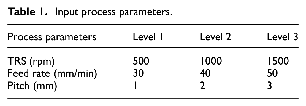
In this work, the nylon 6A is utilized which is a polymer for reproducing the properties of nylon 6,6 with non-violation of patent on the production. It is relevant to the semi-crystalline polyamide. Unlike any other nylons, nylon 6A is not a condensation polymer. But ring-opening polymerization is formed that makes a special case by comparing between addition polymers and condensation. In general, fibers of nylon 6A are tough to deal with because they contain elasticity, high tensile strength, and luster. They are resistant to the chemicals and abrasion highly such as alkalis and acids. Usually, 2.4% of water can absorb by the fibers even though it reduces the tensile strength. Moreover, it includes the glass transition temperature of 47°C. In prior to the generating of different color results, nylon 6A can be dyed in a solution path as it is white as a synthetic fiber. The heat protection is up to 150°C, the melting point is at 215°C, a density is 1.14 g/cc, and the tenacity is between 6 and 8.5 g/den. Twelve percentage of ledeburitic chromium tool steel includes in D3 steel with the great resistance of wears. However, it can be used as cutting tools for shear cutting edges, blanking dies for paper and plastics, sheets up to 4 mm thickness, and rotational shear edges with the thicknesses of sheets up to 2 mm. High chromium 12% tool steel and 2% of high carbon with high wear resistance are the major properties of D3 steel. After making the dies and tools, the hardness is 57–58 HRC is reached using this D3 steel that anneals to easy machining based on its supply condition. Figure 2 demonstrate the ASTM standard specimen dimensions for UTS. This work utilized the DOE method for collecting the data and obtaining the accurate results. Three process parameters like pitch (mm), feed rate (mm/min), and TRS (rpm) have chosen for orthogonal array (L27) and the results are analyzed using MINITAB 19 software. In addition, the HCHCr tool is used to join the work piece and the hardness, UTS are measured as output responses of FSW joint. Table 1 listed the values of input process parameters with corresponding levels.
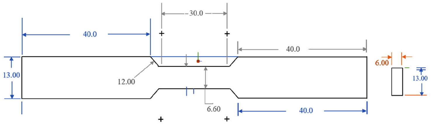
ASTM standard specimen dimensions for UTS.
Input process parameters.
Taguchi method
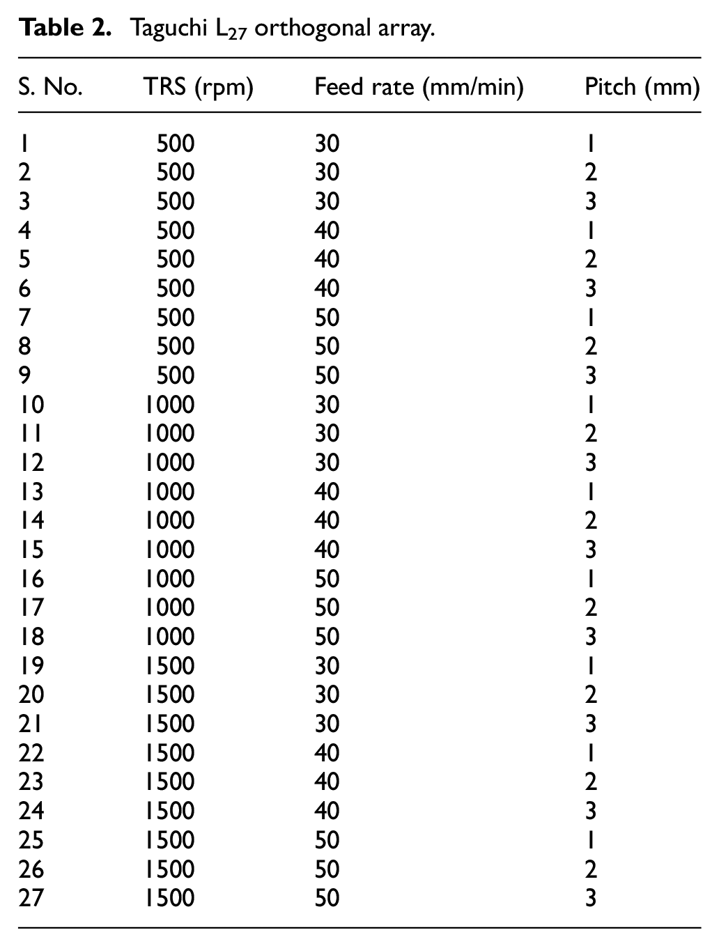
In the machining processes, the most utilized robust design approach is the Taguchi technique, which was analyzed for finding the controllable parameters with the best characteristics of response in FSW. In the experimental designs, the Taguchi technique is used based on orthogonal array for reducing the uncontrollable components effects while establishing the tests. Owing to the constant distribution of interactions between facts and the input components, Taguchi L27 orthogonal array as demonstrated in Table 2 is used for the experiments to minimize the uncontrolled components. The Taguchi design of experiments have evaluated to obtain the data through the conversion it to signal-to-noise (
Taguchi L27 orthogonal array.
Static and transient thermal analysis
CAD is a computer software tool employed for the design of product and CAM is a computer software/hardware that is utilized for controlling, planning, and managing of manufacturing product operations. CATIA stands for computer-aided 3-D interactive application, which is a leading 3-D software tool utilized in most of the industries from automobile, and aerospace fields. Figure 3(a) and (b) demonstrate the design of a tool with taper thread and the assembly process of FSW, respectively. The two-dimensional (2-D) model of tool with taper thread is illustrated in Figure 4.
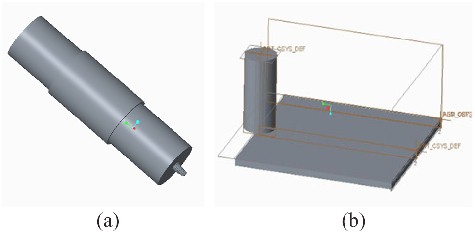
(a) Design of taper threaded tool and (b) assembly of FSW process.

2-D model of taper threaded tool.
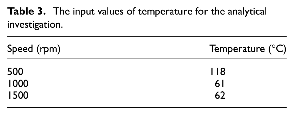
Here, the mechanical properties such as strain, stress, distribution of temperature, deformation, and heat flux are considered for the analytical examination of FSW process on nylon 6A. Table 3 listed with the values of temperature for the analytical investigation. CATIA is used to design the model, then meshing, and analysis are by importing the designed model into the Ansys workbench. The element is decomposed into couple of connected volumes for meshing as shown in Figure 5. Total 360 intervals are used to mesh all the thickness edges of tetrahedral mesh with the overall number of nodes and elements as 16,176, and 8244, respectively.
The input values of temperature for the analytical investigation.
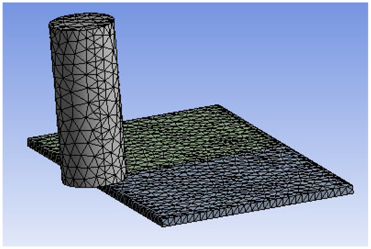
Meshed model.
The observed total deformation and stress at nylon 6A material is demonstrated in Figures 6 and 7, respectively. The red color indicates the maximum deformation, which is about 0.0028608 mm and the minimum deformation is denoted with blue color that is, 0.00031786 mm. Similarly, maximum stress developed on weld zone and tool, which is represented in red color that is, 25.771 N/mm2 and minimum stress is developed on the workpiece material of nylon 6A, which is denoted in blue color that is, 0.0003864 N/mm2. Figure 8 depicts the analysis of strain on nylon 6A workpiece, where the maximum stain (i.e. 0.000346) is observed at weld zone and tool, which is represented in red color and the minimum strain of 8.198e−08 is obtained at workpiece and denoted in blue color.

Total deformation at material of nylon 6A.

Stresses at material of nylon 6A.

Strain at material of nylon 6A.
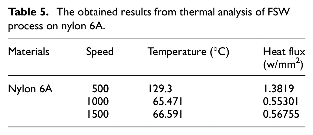
Figures 9 and 10 demonstrate the temperature distribution and heat flux analysis of a workpiece material made by nylon 6A. As seen from Figure 9, the maximum temperature about 129.3°C indicated in red color is observed on the weld zone and tool, whereas the minimum temperature of 22.015°C represented in blue color developed at workpiece material of nylon 6A. From Figure 10, it is observed that maximum heat flux of 1.38 W/mm2 is denoted in red color and the minimum heat flux of 3.12e−6 W/mm2 is represented in blue color. Tables 4 and 5 illustrated the obtained results of both statistical and thermal analysis FSW process on nylon 6A.

Temperature distribution of nylon 6A.
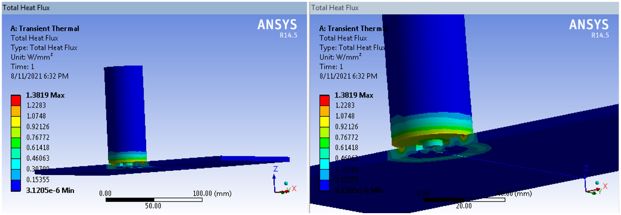
Heat flux of nylon 6A.
The obtained results from static analysis of FSW process on nylon 6A.

The obtained results from thermal analysis of FSW process on nylon 6A.
Experimental investigation
This section describes the experimental investigation, which is done to verify the mechanical attributes of FSW on nylon 6A (also known as polycaprolactam material) as shown in Figure 11(a). Here UTS, and hardness are employed as the properties to be investigated before and after the process of FSW. The work is done using an automatic fed vertical milling machine by setting the TRS and feeds accordingly with the taper threaded tool profile consideration as shown in Figure 11(b). Figure 12 illustrates the machining set up of FSW with the underneath specifications.
Capacity of motor – 7.5 hp
Speed of rotation – 35 to 750 rpm
Feed rate – 16–800 mm/min.
Make – HMT.
Size of bed –
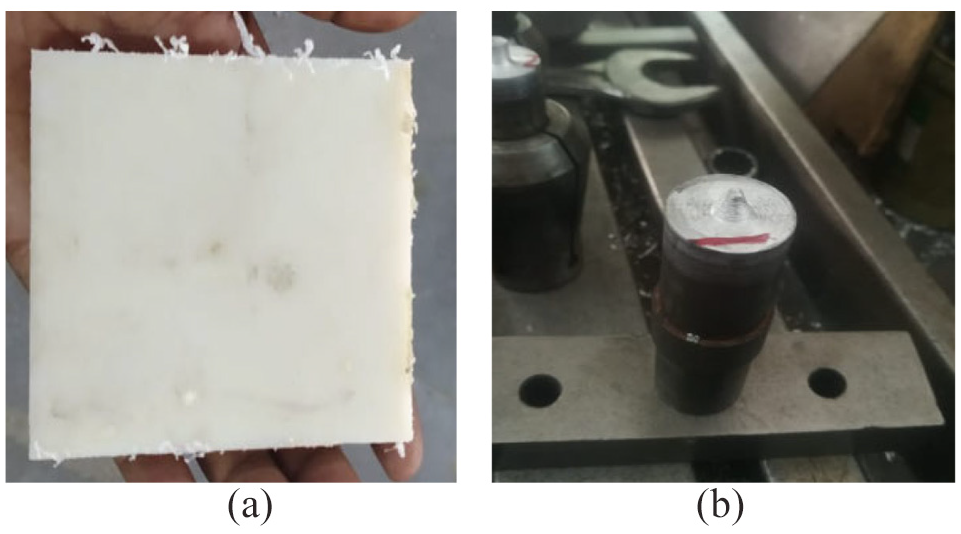
(a) Raw material of nylon and (b) taper threaded tool.

Machine used for FSW.
The tool
Tool steel is the mixture of variety of alloy and carbon steels, and they are well-suited for using them as tools due to their suitability, distinctive hardness, ability of holding a cutting edge at elevated temperatures, and resistance to abrasion and deformation. Thus, tool steels can be exploited for shaping of other materials. Tool steels contain six groups such as hot-work, high-speed, shock-resisting, cold-work, water-hardening, and special purpose. Based on the toughness, shock resistance, strength, required surface hardness, working temperature, and cost requirements, the group choice has been selected. In this work, HCHCr is considered as tool material and its specifications are given below.
Tool length – 100 mm.
Tool tip’s diameter – 2 mm.
The pin length – 4.7 mm.
Tool shoulder’s diameter – 20 mm.
Process
The plates with dimensions are considered as

(a) Workpiece clamping, (b) FSW process, and (c) final specimen joint.
Results and discussion
This section describes the results obtained using FSW process of nylon 6A material and HCHCr tool with taper threaded tool profile by varying the pitch values. Here, TRS (rpm), feed rate (mm/min), and pitch (mm) are considered as input process parameters while the UTS and hardness are assumed as output parameters, which means the strength of welding is assessed using these UTS, and hardness values. As we need the maximum tensile strength, the input parameters performed the concept of larger the better criteria. Table 6 listed with the obtained experimental output parameters such as UTS, and hardness with the variation in input process parameters like TRS (rpm), feed rate (mm/min), and pitch (mm).
Obtained experimental results of UTS, and hardness.

Analyze of variance (ANOVA)
The ANOVA is employed to measure how the input operating process parameters influences the output response parameters that is, mechanical attributes of welded joints, via the association between these two input and output variables, where the fisher test is applied to measure the significance degree in these relationships. In this work, the maximum tensile yield stress in analyzed. For each control factor, ANOVA is required to be estimated for accessing the factors impact on response. To investigate which design parameters effecting the characteristic significantly, the experimental results have assessed using the method of ANOVA, which can identify the input parameters contributions on UTS, and hardness. To detect the process parameters whose variance in the design space that impacting the output response metrics, ANOVA is applied while choosing 90% of confidence interval for experimental investigation. If the computed probability
Major factors and corresponding p values for the process of FSW.

Regression analysis
After the process of weld joining, the regression analysis is conducted based on the obtained data results. The linear equations are derived that relevant to the dependent and independent variables, which is performed using Minitab software and the regression equations are mentioned below:
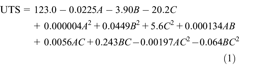

Based on the listed values of
Residuals for all the performance measures.

For detecting the control factors, robustness is measured in Taguchi designs that decrease the product or process variability while minimizing the uncontrollable factors’ effects (noise factors). Design parameters are control factors and controllable parameters are process parameters. During product use or production, noise factors cannot be controlled, but it can be controlled during experimentation. For force variability to occur, the noise factors are calculated in a Taguchi designed method. The settings of optimal control factor detect to make the process or product resistant or robust toward variation against noise factors. The control factor settings indicate by higher values of
Process parameters effect on UTS
Table 9 listed with the response values for
Response for

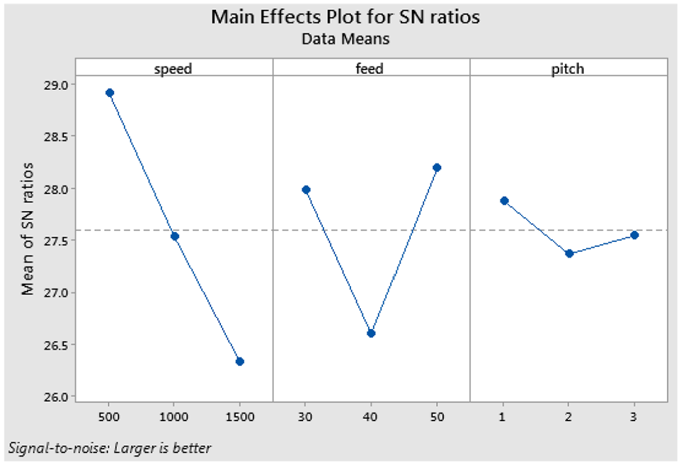
Main effect plot for
Process parameters effect on hardness
Table 10 demonstrate the response for
Response for


Main effect plot for
Microstructure analysis
From the polymer composite of nylon 6A, the samples with metallographic structure are considered, which are later integrated with the FSW and then examined in detail. FSW joints include the structures that contain thermo mechanically affected zone (TMAZ), base metal (BM), heat affected zone (HAZ), and nugget zone as demonstrated in Figure 16. These structures have studied in both micro and micro size. In addition, from the welding joints’ cross-sectional surfaces, micro and macro-structure-based images have taken, which are illustrated in Figure 17.

Formed zones in the weld cutaway in the FSW method.

Obtained microstructural images with different welding parameters: (a) TRS: 500 rpm, and feed rate: 30 mm/min, (b) TRS: 500 rpm, and feed rate: 40 mm/min, (c) TRS: 500 rpm, and feed rate: 50 mm/min, (d) TRS: 1000 rpm, and feed rate: 30 mm/min, (e) TRS: 1000 rpm, and feed rate: 40 mm/min, (f) TRS: 1000 rpm, and feed rate: 50 mm/min, (g) TRS: 1500 rpm, and feed rate: 30 mm/min, (h) TRS: 1500 rpm, and feed rate: 40 mm/min, and (i) TRS: 1500 rpm, and feed rate: 50 mm/min.
Based on the TRS and feed rate, structures have been changed. The wide gaps have observed in the joining zones if the welded sample’s microstructure has examined with the TRS of 1500 rpm and a feed rate up to 50 mm/min. The less porosity has occurred at the joining zones if the welded sample’s microstructure has tested with the TRS of 500 rpm and a feed rate of 30 mm/min. Then, the material is extruded to join better. In the welding center, the gaps are observed. In the welded joints, the amounts of gaps and size are getting increased by increasing the value of feed rate and TRS. In the defects’ size, the increment is predicted with the reducing of temperature in the unit time and area.
Conclusion
This article proposed an experimental and thermal investigation of FSW process on nylon 6A polymer material using HCHCr tool with taper threaded tool profile by varying the pitch values. In addition, optimal process parameters are obtained using Taguchi’s L27 orthogonal array approach. Further, ANOVA with regression equations also done to disclose the effectiveness of input operating process parameters impact on the output responses like UTS, and hardness. The final conclusions made form the obtained experimental and optimized results are as follows:
The results of Taguchi proven that the mathematical models have an ability to forecast the parameters of FSW with the confidence interval of 95%.
The most significant and the least significant FSW parameters are the tool rotation, and feed rate, respectively.
>The parameters like feed, and TRS have considered for FSW joints UTS of nylon 6A polymer composite.
The optimum FSW parameters such as the feed rate of 30 mm/min, tool pitch of 3 mm, and the TRS of 500 rpm have obtained the maximum UTS.
FSW technique joined with the micro and macrostructures of welding joints have shown the varied welding seams relied on welding parameters, which has impacted the value of hardness. The major difference between hardness values of joints was that the differed hardness values with the heat influence although the joints’ hardness values have made with both pin geometries. In the experiments, the lowest and highest hardness values have been computed. The maximum and minimum hardness values have obtained for the feed rate of 30 mm/min, TRS of 1500 rpm, and the feed rate of 50 mm/min, TRS of 500 rpm, respectively.
Footnotes
Handling Editor: Chenhui Liang
Declaration of conflicting interests
The author(s) declared no potential conflicts of interest with respect to the research, authorship, and/or publication of this article.
Funding
The author(s) received no financial support for the research, authorship, and/or publication of this article.