
Abstract
The operating characteristics of a centrifugal pump with broken impeller malfunction was studied by tests and numerical simulation. One blade was cut 1/4 as a broken impeller. The energy characteristics, vibration, internal flow, pressure fluctuation, and radial force of the pump were studied in detail. The test results show that as for the pump with broken impeller, the head decreased by 9.85% and efficiency decreased by 1.06% under 1.0 Q0. The vibration increase amplitudes at the outlet flange are the maximum. The APF (axial passing frequency) of all monitoring points increased significantly, and a new frequency – 5APF appeared, except for the inlet of the pump. It can be found that the low-speed region of blade fracture surface is more obvious than other blades through numerical simulation. The radial force of the broken impeller increased obviously and became more concentrated. Due to the broken blade, the peak-to-peak magnitude of pressure fluctuation at the tongue and pump outlet increased by 4.7% and 9.5% respectively. The research results provide some reference for the malfunction diagnosis of centrifugal pump.
Introduction
As a general-purpose rotating machinery, the centrifugal pump is the core power equipment of many transportation systems. However, in practical operation, the centrifugal pump will be affected by rotor vibration and fluid excitation for a long time, and some malfunctions will inevitably occur, threatening the safety of the unit and personnel.1–3 Therefore, the research on the malfunction monitoring and operation characteristics of centrifugal pump has gradually become the focus.4,5
In the field of malfunction diagnosis of rotating machinery, it is mainly analyzed according to the collected signal state, and then further classified and identified.6,7 Samanta 8 and Ben Salem et al. 9 used the sensing signal to realize the mechanical malfunction diagnosis of gear and induction motor respectively. Wang 10 realized the identification, classification, and detection of steam turbine malfunctions according to the vibration signals of steam turbine units. Generally, the malfunction diagnosis method of rotating machinery is used in the malfunction diagnosis of most centrifugal pumps. Shi 11 studied the typical damage mechanism and malfunction characteristics of the pump under the phenomenon of sudden drop in efficiency and pump shaft stuck. Zhu 12 studied and monitored the damage phenomena such as wear of centrifugal pump mouth ring and shaft seal leakage. Hong et al. 13 diagnosed the malfunction of centrifugal pump through performance parameters and vibration signals. Yang 14 realized the cavitation malfunction diagnosis according to the performance change of the centrifugal pump in the cavitation state. Liang 15 studied the dynamic characteristics of vibration signals of centrifugal pumps in different states, thus realizing the identification of different vibration malfunctioned states.
At the same time, most scholars mainly analyzed the influence of different factors on the operation characteristics of the centrifugal pump to further provided a basis for malfunction diagnosis and prediction.16,17 Howe 18 analyzed the vibration characteristics of the blade under the coupling action of the centrifugal pump blade and the internal flow field. Elemer and Douglas 19 studied the effectiveness of sealing rings in reducing the vibration of centrifugal pumps. Wan 20 studied the wear characteristics of centrifugal pump under the influence of different geometric parameters. Mele et al. 6 and Srivastav et al. 2 studied the effects of centrifugal pump speed and tip clearance on the vibration characteristics of the structure. Parrondo-Gayo et al. 7 studied the characteristics of pressure fluctuation in the pump under the influence of the intensity of dynamic and static interference between the tongue and the impeller. Spence and Amaral-Teixeira, 17 Khalifa, 21 and Lino et al. 22 analyzed the effects of structural parameters of several components on the frequency spectrum and energy characteristics of pressure pulsation.
In summary, researchers have done a lot of research on the malfunction monitoring and operation characteristics of centrifugal pump. But so far, there is little research on centrifugal pump with broken impeller, which is very likely to happen in practical application. In this paper, a centrifugal pump with broken impeller is selected as the research object. The energy characteristics, vibration characteristics, internal flow characteristics, radial force and pressure pulsation of damaged impeller centrifugal pump, and ordinary impeller centrifugal pump are compared and analyzed by means of experimental test and numerical simulation. The purpose of this paper is to provide reference for the malfunction diagnosis of centrifugal pump damaged by impeller.
Research model and scheme
Physical mould
A vertical single-stage single-suction centrifugal pump model is chosen as the research object. The design flow rate Q0 = 25 m3/h, head H=34 m, speed n = 2950 r/min, and specific speed ns = 66.7. The impeller inlet diameter D1 = 65 mm, the impeller outlet diameter D2 = 165 mm, the number of impeller blades Z = 6, and the diameter of the volute D4 = 50 mm.
Research scheme
The normal blade and broken blade are shown in the Figure 1. To obtain a broken impeller, one blade was cut 1/4. To be convenient, use BBP to represent broken blade pump model, use NBP to represent normal blade pump model.

Normal impeller and broken impeller: (a) normal impeller and (b) broken impeller.
Mathematic model
Expression of average vibration amplitude:

The expression of the total vibration level:

In the formula, A is the effective value of the measured vibration acceleration, and the unit is m/s2, A0=1E − 6 m/s2 as the reference value.
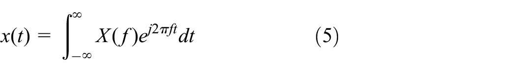
The time domain signal x(t) satisfies the Dirichlet condition:

Then the Fourier transform exists and is defined as:

Where, X(f) is the signal frequency domain representation, f represents the signal frequency.
The inverse transformation is as follows:
The (IDFT) formulas of discrete Fourier transform and discrete inverse Fourier transform are as follows:
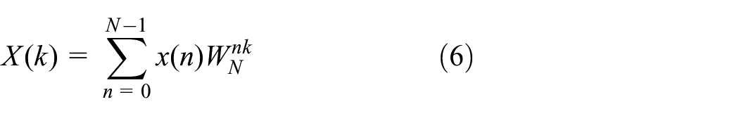

Where N is the number of sampling points:

The transport equation of the turbulence model is:
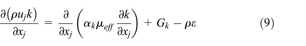

In the formula: μeff = μ + μt, Cμ = 0.0845, α k = 1.39, α ε = 1.39, C1 = 1.42, C2 = 1.68, η0 = 4.377, and β = 0.012.


Test scheme and numerical simulation method
Test method
Test system
The test bench is shown in Figure 2. The test bench is composed of test pump, inlet and outlet water circulating pipe, circulating water tank, computer, and vibration acceleration sensor. The outlet valve is used to regulate flow rate and the flow rate is obtained by KEF electromagnetic flowmeter, its measurement accuracy is 0.5. The pressure fluctuation of the pump outlet and the tongue are monitored by the pressure pulsation sensor, the measurement range is −100 to 100 kPa, and the measurement accuracy is 0.2. The vibration transducers are fixed at the volute, the inlet flange, outlet flange, the machine base, the motor bracket, and the pump bracket. The sensitivity of the vibration transducers is 100 mV/g. The vibration sampling frequency is 25.6 kHz, the sampling time is 30 s.

Test rig.
Vibration monitoring locations
To analyze the vibration, four monitoring points are selected. The position of each monitor is shown in the Table 1 and Figure 3.
Location of monitoring points.


Monitoring points.
Numerical calculation methodology
Vibration monitoring locations
The three-dimensional model of the full flow zone of the model pump is made by Creo 2.0. The flow domain includes the inlet pipe, impeller, seal ring gap, the volute, and outlet pipe. To improve the simulation accuracy, the inlet and outlet pipe sections are properly extended. The watershed model diagram is shown in the Figure 4. The Reynolds-averaged Navier-Stokes equations are solved by the RNG k-ε turbulence model, because the model improves the accuracy of high-speed flow and vortex flow to a certain extent. 23

Full flow field water body modeling of model pump.
Based on ICEM-CFD, structured grids were applied to discretize the computational domain. Compared to the unstructured grids, the structured grids were more precision and similar to the original model. The grid diagram is shown in Figure 5.

Fluid domain grid of model pump: (a) impeller, (b) leakage channel, (c) volute, (d) inlet bend and extension section, and (e) outlet extension section.
When meshing the computing domain, the quality and quantity of grids will directly affect the convergence and accuracy of simulation calculation. The water body of the model pump is divided into five sets of grids with different number of grid units, and the head of the model pump is simulated. It is observed that the predicted head almost doesn’t change any more after scheme 3. The specific scheme is shown in Table 2. So take the calculation resource and accuracy into consideration, the third scheme is chosen for subsequent calculation.
Grid independence check.

Test verification
To ensure the accuracy of simulation method, the performance curves of NBP are obtained by numerical simulation and test respectively and Figure 6 shows the results.

Performance curves comparison of NBP between numerical simulation and test.
As shown in the Figure 6, the numerical simulation results are in good agreement with the test results. At design flow rate, the prediction deviation of head is 1.9% and the prediction deviation of efficiency is 4.34%. The deviations of head and efficiency are all within 5% at off-design flow rates. Therefore, this numerical simulation model is reliable.
As can be seen from Figure 6, the numerical simulation results are basically consistent with the test results. Under the rated condition, the deviation of head calculation result is 1.9%, and the deviation of efficiency calculation result is 4.34%. Under non rated conditions, the deviation between the two calculation results is basically kept within 5%. Therefore, this numerical simulation model is reliable.
Test and analysis
Energy characteristics
Figure 7 shows the energy characteristics comparison between NBP and BBP. It can be clearly seen that the pump head has been greatly affected by the fracture of the impeller. The pump head decreased by 9.85% under the rated operating conditions and the head decreases by 21.7% under the condition of large flow. For the BBP, the efficiency changes little under the small flow rate, and it presents a decrease trend when the flow rate is bigger than the design condition. At the 1.0Q0 condition the efficiency decreases by 1.06% and the efficiency decreases by 7.55% at 1.4Q0. It is obvious that the broken blade will cause the decrease of the pump head and efficiency and the decrease gradually become larger with the increase of the flow rate. This may be due to that the shorter blade cannot give enough energy to the liquid during impeller rotation, and it becomes more serious with the increase of flow rate. Compared with the change of pump efficiency, the broken blade has more influence on the pump head.

Energy performance comparison between NBP and BBP.
Vibration performance
Vibration amplitude
Vibration velocity amplitude is the product of vibration displacement and frequency. The amplitude reflects the influence of vibration frequency and displacement amplitude at the same time, which is more comprehensive than simple vibration displacement amplitude. Figure 8 shows the vibration velocity magnitude comparison between NBP and BBP. From Figure 8(a), it can be seen that the vibration magnitude at all measuring points of NBP decreases first then increases with the increase of flow rate, and the vibration amplitude is minimum under design conditions. As shown in Figure 8(b), the vibration magnitude at the rest of the measuring points all increased to varying degrees due to broken impeller. The decrease of vibration amplitude at M4 (volute) may be due to that the broken blade make the interaction between impeller and volute weaker.
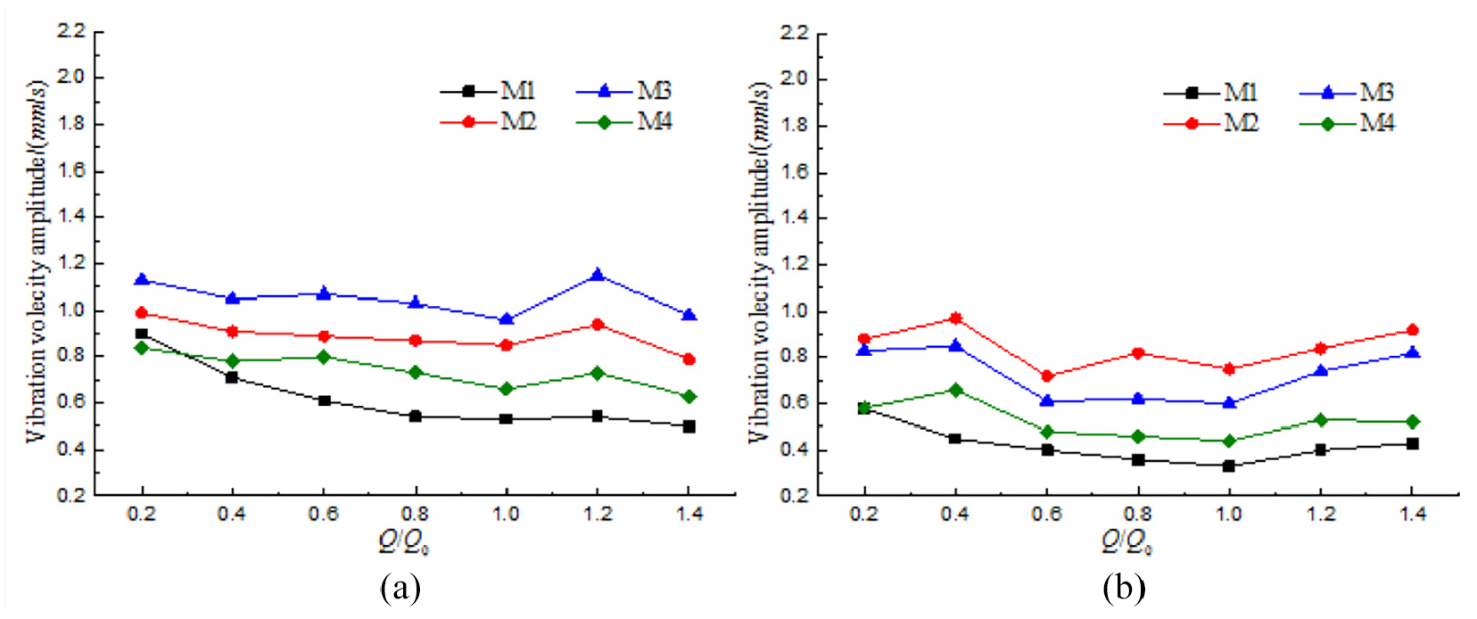
Vibration magnitude comparison between NBP and BBP: (a) NBP and (b) BBP.
Under design flow rate, the further quantitative analysis indicates that the vibration increase amplitudes at M2 (outlet flange) of BBP are all the maximum, about 50%.
General vibration amplitude
Figure 9 shows the ordinary vibration magnitude comparison between NBP and BBP under 0.8 Q0, 1.0 Q0, and 1.2 Q0. It can be found that the general vibration at M2 is the biggest under all flow rates, no matter it is BBP or NBP. For NBP and BBP, the general vibration level at M1 (inlet flange) is larger under 0.8 Q0, but smaller under 1.0 Q0 and 1.2 Q0. This is due to the backflow phenomenon when the flow is small, which aggravates the vibration at the inlet. The general vibration of BBP increases most at M2, and it increases 3.3, 3.66, and 4.15 dB at 0.8 Q0, 1.0 Q0, and 1.2 Q0 respectively.

A caption on a single line should be centered. General vibration amplitude comparison between NBP and BBP: (a) 0.8 Q0, (b) 1.0 Q0, and (c) 1.2 Q0.
To sum up, when the vibration at volute decreases and the vibration at motor bracket or pump outlet increases obviously, the malfunction of broken blade should be consider firstly.
Vibration spectrum
Figure 10 presents the vibration velocity in frequency domain. From Figure 9, it can be found that the all vibration amplitudes at APF change obviously under each flow rate due to broken blade. For M1, when the blade is broken, the vibration magnitude at APF (axial passing frequency) decreases under all flow rates. As for the other measuring points, while the vibration amplitudes at APF all increase, and the increase magnitude is more prominently than that at BPF (blade passing frequency) amplitude. And so are the vibration amplitudes at 2APF. The increase amplitude of M2 at APF is the maximum, and is 117.5%. This is mainly due to the uneven force distribution in the impeller caused by the broken blade, which has a great influence on the vibration at APF and its harmonic frequency.

Vibration velocity in frequency domain: (a) M1, (b) M2, (c) M3, and (d) M4.
Because of the broken blade, there appear more characteristic frequencies on the vibration frequency spectrum curves and the frequency spectrum gets more unevenly. Among the new characteristic frequencies, 5APF is the most obvious, which appears at measuring points. The main reason is that the interaction between the impeller and the volute tongue turns to be five times due to the broken impeller. The vibration magnitudes of M1, M2, M3, and M4 at 5APF are 0.2, 0.41, 0.27, and 0.13 mm/s respectively under 1.0 Q0. Therefore, when the 5APF is found in vibration frequency spectrum curves, it is possible that one blade is broken.
To sum up, the broken blade will cause the increase of the pump vibration especially the vibration at the pump outlet. Based on the analysis of frequency spectrum, it can be seen that the increase of vibration magnitude is very obvious at APF and 2APF increase. Besides, the total frequency spectrum becomes more non-uniform, and the characteristic frequency that has not appeared before is shown at 5APF.
Numerical simulation study
Internal flow performance
Figure 11 presents the velocity distribution in impeller. For NBP, The impeller speed distribution is uniform, and the low-speed region is symmetrically distributed near the pressure side of each blade. For BBP, the relative velocity distribution becomes non-uniform near the broken blade, and the low velocity zone near the side of broken blade surface becomes larger evidently. There exists a larger vortex flow at the inhalation position of blade damage location, which can make hydraulic loss increase and pump performance decrease rapidly.

Velocity distribution in impeller (1.0 Q0): (a) NBP and (b) BBP.
Radial force of impeller
The radical force on normal and broken impeller is monitored to obtain the change law of the impeller radial force.
The radical force inside the impeller is compared between NBP and BBP. Figure 12 is the comparison curves of radial force. For NBP, the radical force inside the impeller changes periodically in one rotation cycle. There are six wave peaks and troughs, which is in accordance with the blade number. After the blade is broken, the periodicity of radial force is no longer obvious and the curve becomes disorder. The quantitative analysis indicates that the peak-to-peak value of the radial force increases by 2.16 times and the average of radial force increases by 28.76 N. That is because the broken blade makes the impeller structure unbalance. Therefore, the radial force gets unsteady and larger during the impeller rotation.
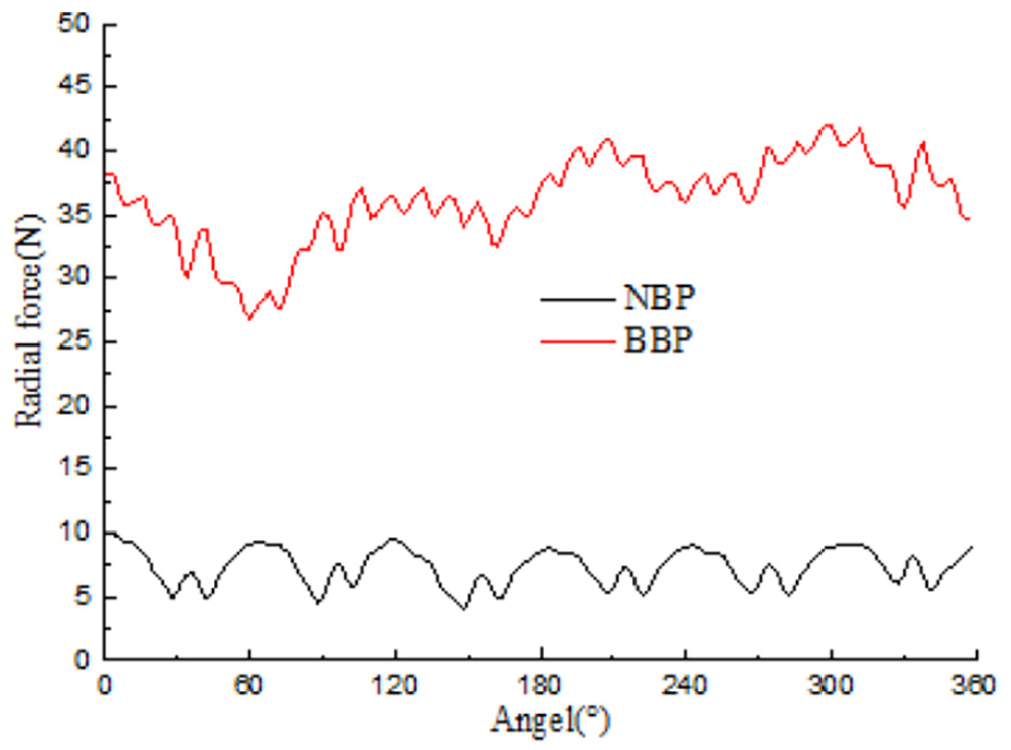
Radical force inside the impeller.
Figure 13 shows the vector distributions of the radial force in the normal and broken impeller. The vector of the radical force in the normal impeller has hexagonal symmetry distribution, which corresponds to the six periods in the time domain diagram. For BBP, the vector distribution of the radial force changes greatly and the radical force becomes larger and its distributions is no longer uniformly and symmetrical. The radial force vectors are all in the third quadrant, which means the radial force can’t change periodically during impeller rotation and its direction mainly points to the sixth section of the volute. Therefore, the radical force in broken impeller is very concentrated, which would result in the obvious increase of the alternating stress of the rotor and the directional deflection of the pump shaft. As a result, it will cause damage to the pump in the long term.
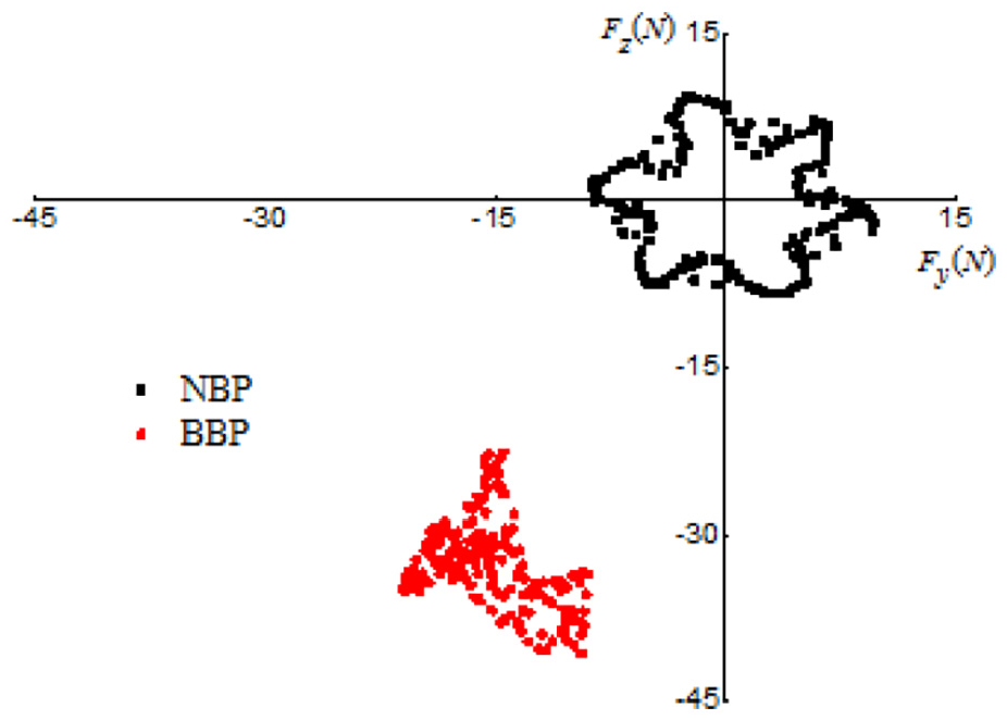
The vector distribution of radial force in impeller.
Pressure fluctuation
The pressure fluctuation at the volute tongue and outlet of the pump is the most representative. So two monitoring points are set at the volute tongue and outlet of the pump to monitor the pressure fluctuation in the pump. The specific monitoring point locations are shown in Figure 14.
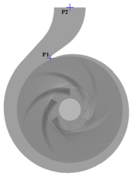
Monitoring points of pressure fluctuation.
Figure 15 shows the time domain curves of pressure fluctuation during two impeller rotation cycles, respectively. From Figure 14, it can be seen that the pressure pulsation in the NBP are similar to that in the BBP and pressure pulsation at P1 is larger than that at P2. All the curves show the good periodicity. By compassion in detail, it can be found that there are six wave peaks and troughs during a period in NBP. But it is five in BBP. This is because the number of rotor-stator interaction has reduced to be five in BBP. The quantitative analysis indicates that the peak-to-peak magnitude of pressure fluctuation at P1 increases by 4.7% due to the broken blade and it is 9.5% for pressure pulsation at P2. So, the peak value of the P1 increases by 4.7%. The peak value of P2 increases by 9.5%. The number of rotor-stator interaction decreases because of the broken blade, but the intensity of rotor-stator interaction increases.

Pressure fluctuation in time domain: (a) P1 and (b) P2.
Figure 16 is the pressure fluctuation curves in frequency domain. In Figure 16, it can be found that the pressure pulsation is mainly at APF and BPF for both NBP and BBP. The broken blade has a great influence on pressure pulsation at the APF and its harmonic frequency, but has less effect on pressure pulsation at the BPF. After the blade breaks, the pressure pulsation of P1 and P2 at APF increase by 11.2 times and 18.9 times. The APF, BPF, 2BPF, and 3BPF become obvious. This is mainly because the impeller structure gets unbalance due to the broken blade, the force induced by inner flow gets more unsteady.

Pressure fluctuation in frequency domain: (a) P1 and (b) P2.
Conclusion
This paper presents the experimental and numerical simulation results of centrifugal pump impeller fracture fault. One blade is cut 1/4 as the broken impeller. The energy performance, flow characteristics, pressure pulsation, and radial force of the pump are studied in detail. And the results are showing in the following.
The energy characteristic curve shows that the broken blade has a great influence on the pump head and efficiency. The head and efficiency decrease obviously with the flow. The pump head decreased by 9.85% and the efficiency decreases by 1.06% under the rated operating conditions.
The broken blade malfunction aggravates the vibration at the pump outlet. Under the design flow rate, the vibration increase amplitude and the general vibration level are both reaching maximum at M2 (outlet flange) of BBP and they increase about 50% and 3.66 dB respectively. Under 1.0 Q0, the increase amplitude of APF at M2 is the maximum, and is 117.5%. When the pump works under the broken blade malfunction, the amplitude of AFP increased obviously. The vibration amplitudes of 5APF at M1, M2, M3, and M4 are 0.2, 0.41, 0.27, and 0.13 mm/s respectively.
For the BBP, the relative velocity distribution becomes non-uniform and there exists a larger vortex flow at the inhalation position of blade damage location.
For the BBP, the periodicity of radial force is no longer obvious and the curve becomes disorder. In one rotating period, the peak-to-peak magnitude of the radial force increases by 2.16 times and the average of radial force increases by 28.76 N. The radial force vector direction is no longer uniformly and symmetrical, and its direction mainly points to the sixth section of the volute.
When the blade is broken, there are five wave peaks and troughs during a period, the peak value of P1 increases by 4.7%, and the peak value of P2 increases by 9.5%.The pressure pulsation of P1 and P2 at APF increase by 11.2 times and 18.9 times.
Footnotes
Appendix
Handling Editor: Chenhui Liang
Declaration of conflicting interests
The author(s) declared no potential conflicts of interest with respect to the research, authorship, and/or publication of this article.
Funding
The author(s) disclosed receipt of the following financial support for the research, authorship, and/or publication of this article: The authors gratefully acknowledge the support from the National Natural Science Foundation of China (Nos. 51979124, 51779108). The authors gratefully acknowledge the support from the National Key R&D Plan (2019YFC0312404).