
Abstract
Grinding hardening can obtain hardening effect besides fine machining effect on the surface of workpiece. A certain degree of surface micro-damage will be formed during grinding hardening process which mainly contains micro-crack, melting coating, decarburization, and surface scratch. In order to study the micro-damage of grinding hardening, the paper carries on a grinding hardening experiment and the characteristics of micro-damage are observed. The generation mechanism of micro-crack is revealed. It is formed by the accumulation of dislocation pile-up in the condition of grinding hardening process. When the grinding depth reaches a certain value, the surface micro-crack will be produced obviously and become more serious with the increasing of grinding depth. Other micro-damage containing surface melting coating, decarburization, and surface scratch are also studied and their relevance with micro-crack is revealed. Based on the grinding hardening theory and pile-up dislocation theory, a model for micro-crack of grinding hardening is established. The calculating result of the model accords with the experimental result in general.
Introduction
Grinding process is always performed as the final process in mechanical manufacturing and it has a high machining precision. Grinding hardening in dry condition can produce a certain degree of reinforcement on the workpiece surface.1–3 It uses the large grinding heat and grinding force in grinding process and generates hardening layer on the workpiece surface. It not only improves the surface hardness of workpiece, but also keeps the toughness of internal material. 4 Because of the phase transformation during grinding hardening, there is residual compressive stress in the hardening layer of workpiece.5–8 Therefore, the surface of workpiece will have a good impact resistance, fatigue strength, and abrasive resistance. Grinding hardening combines grinding process and surface hardening into one working procedure. It can not only shorten the processing time efficiently, but also reduce the usage of grinding fluid substantially. So it improves the green degree of the whole process and will have a wide application in the future. The current researches about grinding hardening mainly focus on its hardening effect, the evolution model of microstructure and the characteristics of surface integrity after grinding hardening.
While, seldom attention is paid to the micro-damage of grinding hardening. Grinding process is always regarded as a fine machining.9,10 It can be observed that grinding hardening generates a smooth surface at the macro level from normal vision or under some microscope with small magnification times, and the surface roughness of workpiece after grinding hardening is also small which is tested by the roughness detector. Therefore, it may be thought that the surface of grinding hardening is also smooth in the micro level and seldom attention is paid on it. However, when we move our view to the microscope, things are different. Some micro-damage can be generated on the surface layer of workpiece after grinding hardening which mainly contains micro-crack, melting coating, and decarburization, which is shown in Figure 1.

Forms of micro-damage of grinding hardening.
The micro-damage can be found under microscope with large magnification times such as the SEM (scanning electron microscope) technology. Due to the high temperature and large grinding force,11,12 micro-damage is generated in the hardening layer and changes the smooth state of the surface. Then the initial characteristics of surface layer may be different. They will influence the properties of workpiece such as static strength, fatigue resistance, corrosion resistance, wear resistance, dimensional stability, electromagnetic property, and so on. Therefore, the characteristics and formation mechanism of micro-damage of grinding hardening are important to the manufacturing and material area. Therefore, it is very meaningful to study the micro-damage of grinding hardening. The paper will study the formation and influencing mechanism of micro-damage of grinding hardening based on the experiment and establish a model which can describe the micro-damage of grinding hardening generally.
Grinding hardening experiment
Experimental material
The 45 steel is chosen as the grinding material which is a representative material in industry. Its chemical component is shown in Table 1. The size of specimen is 60 mm × 15 mm × 15mm.
Chemical component of 45 steel.

Selection of experimental target
In the research of micro-damage, the micro-crack is the main form. So it is selected as the main experiment target. The surface melting coating, decarburization, and scratch are selected as the auxiliary targets. In the research of micro-crack, because it may have different length and distribute with no obvious rules, the micro-crack of grinding hardening is difficult to describe in the quantitative way. In order to reveal the general characteristics of micro-crack, the number of the micro-crack in unit area, the length of the shortest and the longest micro-crack in certain area, the mean value and standard deviation of the length of micro-crack are chosen as the concrete experimental targets based on random photograph of SEM observation.
Selection of experimental factor
In common grinding hardening process, the grinding depth and feeding speed are the routine process variables that have impact on the manufacturing effect.13,14 Therefore, the grinding depth and feeding speed are selected as the experimental factor. In order to improve the efficiency of experiment, the given different grinding depth and feeding speed are selected to carry on partial orthogonal experiment.
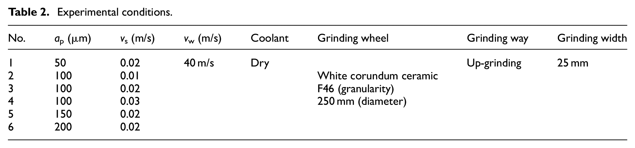
The WE6800-ZC surface grinder is chosen as the experimental grinder. The material of grinding wheel is white corundum ceramic. The granularity size of grinding wheel is F46 and its diameter is 250 mm. The grinding width is 25 mm. The up-grinding and dry grinding are chosen. The whole experimental conditions are shown in Table 2. The grinding process is shown in Figure 2.
Experimental conditions.

Grinding hardening process.
Where, ap is grinding depth; vs is feeding speed; vw is wheel speed.
After the grinding hardening experiment, the surface micro-topography is observed by the SSX-550 SEM tester to carry on the main research on micro-damage of grinding hardening. The metallography of the section of workpiece is shot by OLYMPUS GX71 metallographic microscope as a supplementary research on the micro-damage.
Analysis of micro-crack
Types of micro-crack
The micro-crack is the main micro-damage which is generated during grinding hardening process. Figure 3 shows the surface micro-crack on the surface of workpiece after grinding hardening by using SEM. As is shown in Figure 3, grinding cracks can be mainly divided into three types. The first type of the grinding cracks is the linear crack which is shown in Figure 3(a). Its direction is perpendicular to the grinding direction. And it is close to a line. The type of crack usually has a shallow depth and distributes on the surface uniformly. It has little effect on the service life of workpiece because it usually exists on the shallow layer of the surface. The second type of the grinding crack is the coating crack which is shown in Figure 3(b). The type of crack is formed in the melting coating layer. Considering that melting coating area falls off easily from the surface, coating crack has little influence on the using performance of workpiece. The third type of the grinding crack is the tortoiseshell crack which is shown in Figure 3(c). It is close to a grid with different branches. Tortoiseshell crack belongs to the dangerous type of crack. The type of crack has the deepest depth and has a great influence on the surface quality, performance, and service life of the workpiece. 15 So the tortoiseshell crack should be avoided in the grinding hardening process.
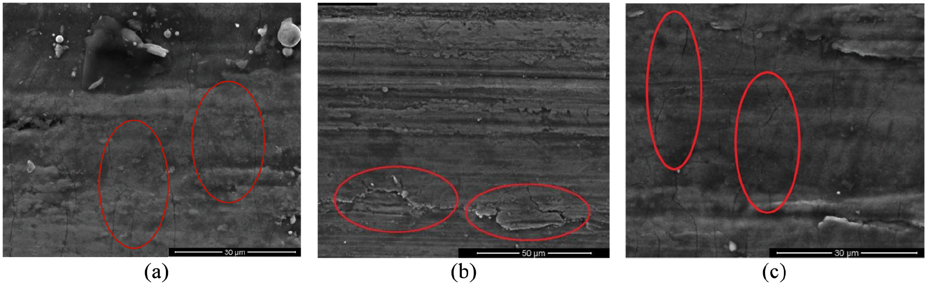
Types of surface micro-crack (ap = 200 μm, vs = 0.02 m/s): (a) linear crack, (b) coating crack, and (c) tortoiseshell crack.
The generation mechanism of micro-crack during grinding hardening is revealed based on the dislocation theory of pile-up. In grinding hardening process, the surface material of the workpiece is impacted by the abrasive grains of grinding wheel, and lots of dislocation is generated in the contacting area of grinding. 16 The movement of dislocation meets obstacle like grain boundary and second-phase particle. If the driving force can’t overcome the obstructive force, the dislocation will stop and pile up in front of the obstacle. When the pile-up reaches a level, the dislocation source of the adjacent grain is activated. 17 Then the micro-crack is produced and grows. This is the basic formation mechanism of grinding micro-crack. If there is no other effect during the process, the basic linear crack will be generated based on it. And when the basic mechanism encounters the high grinding temperature of grinding hardening, the coating crack is generated. Grinding hardening can generate large grinding heat, and the contacting area of the surface of workpiece will have high grinding temperature. Then some area of the surface will melt and forms the melting coating layer. The cooling rate between the melting area and inner layer is different during the cooling process, which produces stretching effect on the melting area. The stretching effect is an extra motivation and accelerates extension of crack besides the initial motivation. Then the melting area will form the coating crack. At last, when the basic mechanism adds phase transformation in grinding hardening, the tortoiseshell crack is generated. As is well-known, martensite with different content can generate during grinding hardening process. The boundary of plate martensite is the natural gap and can provide the way to the extension of micro-crack. If some area has lots of martensite, its new motivation by the gap and original effect can lead to the generation of tortoiseshell crack. Because the plate martensite has random boundary with different direction, it provides different path to the extension of tortoiseshell crack. Therefore, tortoiseshell crack appears with different direction and shows like grid with different branches. Because the plate martensite usually locates in the subsurface layer, the way will extend to the workpiece surface. Therefore, the depth of tortoiseshell crack is relatively large.
Variation tendency of micro-crack
Figure 4 shows the characteristics of micro-crack under different grinding depth. Figure 5 is the representative SEM photograph of micro-crack under different grinding depth. According to the experimental result, the phenomenon of grinding micro-crack increases with the increasing of grinding depth in general. But it varies with nonlinearity. When the grinding depth is small, the size and the number of micro-crack is small, and it lasts for a range. When the grinding depth surpasses a certain value, the size and the number of micro-crack become large suddenly, especially when grinding depth surpasses 150 μm in the experiment. So it can be considered that surface micro-crack will be produced on a large-scale only under the large grinding depth. Different grinding depth has a certain effect on the micro-crack of the workpiece surface.

Effect of different grinding depth on micro-crack.

SEM photograph of micro-crack under different grinding depth (vs = 0.02 m/s): (a) ap = 50 μm, (b) ap = 100 μm, (c) ap = 150 μm, and (d) ap = 200 μm.
The phenomenon is because the dislocation pile-up of the workpiece surface during grinding hardening increases with the increasing of grinding depth. When the workpiece is processed under larger grinding depth, more material is impacted by the abrasive grain, the temperature of the grinding field is higher, larger plastic deformation is generated, and dislocation movement is enhanced.18–20 Then according to the generation mechanism of micro-crack in grinding hardening, the grinding micro-crack increases with the increasing of grinding depth. However, the accumulation of dislocation pile-up is nonlinear. When the grinding depth is small, the small dislocation pile-up produces a little effect on micro-crack. With the increasing of grinding depth, more dislocation pile-up is accumulated. When the phenomenon of dislocation pile-up in unit area accumulates to the critical level, a large quantity of dislocation source of the adjacent grain is activated in the area. Then a large quantity of micro-crack is produced when the grinding depth reaches a certain value. Since the “activation” happens, the phenomenon will reveal even more violently with the continuous growing of grinding depth. And then the micro-crack increases with the grinding depth nonlinearly.
When the grinding depth is small, it can be found that most micro-crack always distributes between two processing traces. Its influencing mechanism is different from the typical micro-crack under large grinding depth which is analyzed in the above paragraph, and it is simply compared with the large grinding depth situation. It can be inferred that the motivation of micro-crack of small grinding depth is weak. Because the extension of crack needs energy, the micro-crack with small motivation can’t extend so much. As the micro-crack is always perpendicular to the processing traces that is cut by the abrasive grain, the processing traces then serve as the natural obstruction for it. Therefore, the extension of micro-crack will be prevented by the processing traces, and most of them can’t cross the hinder of processing traces. In the situation, the micro-crack is influenced by the processing traces.
Figure 6 shows the mean value and standard deviation of the length of micro-crack under different grinding depth. It can be seen that the absolute value of standard deviation increases with the increasing of grinding depth. While, the variable coefficient which is the ratio of standard deviation to each mean value decreases with the increasing of grinding depth. It shows that the micro-crack is relatively more random and discrete when the surface has less crack under smaller grinding depth. And lots of micro-crack is more uniform under larger grinding depth.

Statistics value of micro-crack under different grinding depth.
Figure 7 shows the characteristics of micro-crack under different feeding speed. Figure 8 is the representative SEM photograph of micro-crack under different feeding speed. It can be seen that the micro-crack increases with the increasing of feeding speed. It is because the removal of material under larger feeding speed is more intensive and the grinding strength is a bit larger under larger feeding speed of workpiece. More material is impacted by grinding wheel. Then the dislocation pile-up during grinding hardening process will be a bit larger, which produces more micro-crack relatively. By comparing Figures 4 and 7, it can be seen that the influence of grinding depth is larger than feeding speed. It is because in the common range of grinding parameters, it can be calculated that the increasing of grinding depth will cause a large change of volume of material to be cut by the abrasive grain in unit time. While, in the common change of feeding speed, the change of volume of material which is cut is smaller compared with the change of grinding depth. Therefore, the change of grinding depth will cause more obvious machining effect and more micro-crack.
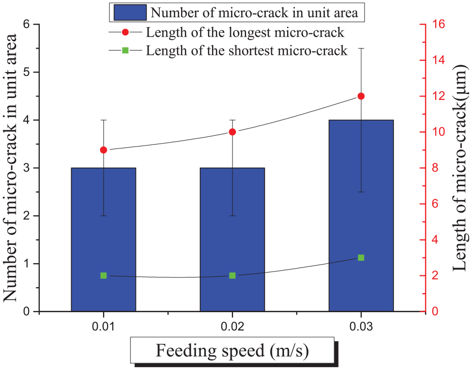
Effect of different feeding speed on micro-crack.

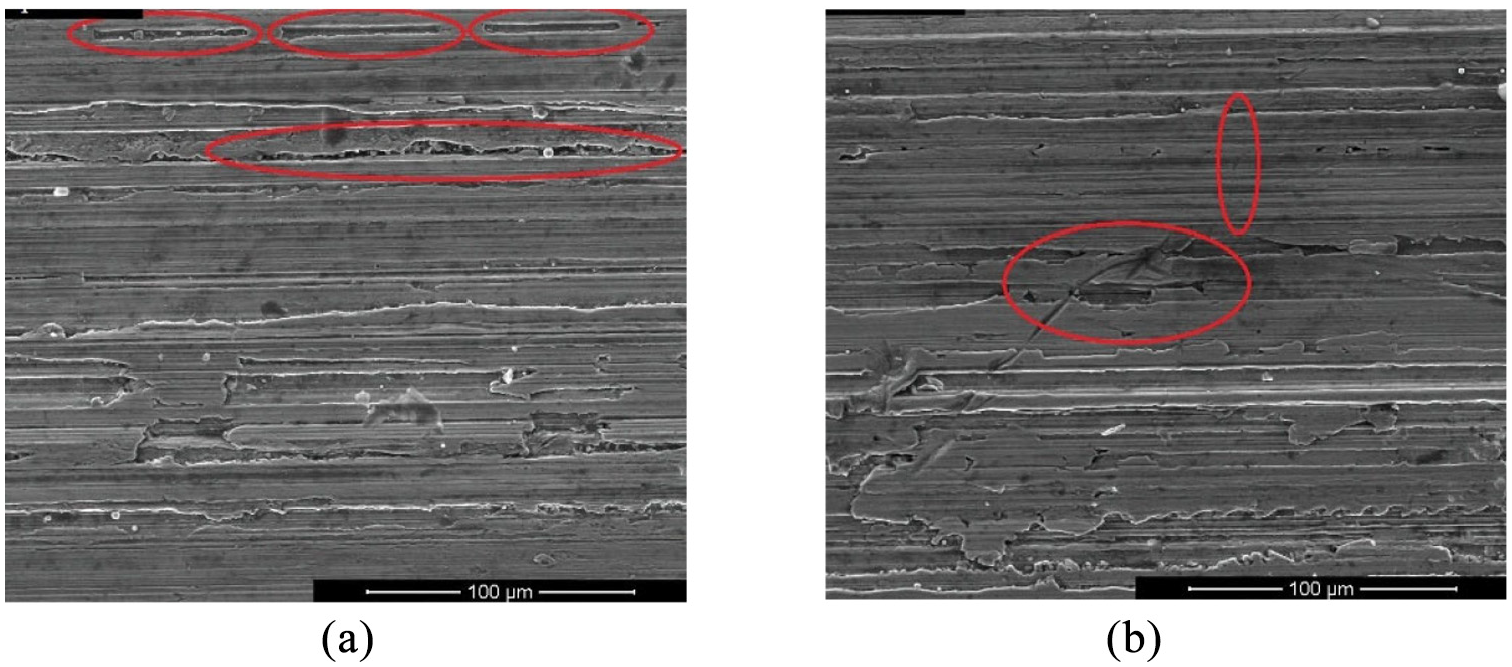
SEM photograph of micro-crack under different feeding speed (ap = 100 μm): (a) vs = 0.01 m/s, (b) vs = 0.02 m/s, and (c) vs = 0.03 m/s.
Figure 9 shows the statistics value under different feeding speed. It can be seen that both standard deviation and variable coefficient are similar, which shows that the dispersion of micro-crack is uniform under different feeding speed.

Statistics value of micro-crack under different feeding speed.
Other micro-damage
Surface melting coating layer
The melting coating layer can be generated on the surface of hardening layer, which is shown in Figure 10. One type of melting coating is the edge coating and it is shown in Figure 10(a). Under super high temperature in the grinding contacting area, a small quantity of surface material will melt. It will flow to the edge of grinding scratch and form the edge coating after cooling.21,22 Another type of melting coating is formed by the flake-like abrasive dust and it is shown in Figure 10(b). Part of abrasive dust will adhere to the workpiece when the grinding temperature is high in grinding hardening, and it may remain on the surface in the cooling process. The abrasive dust coating has irregular shape, and it may cover the melting coating mostly. So the abrasive dust coating will lead to complex topography of the workpiece surface.

Types of surface melting coating layer (ap = 200 μm, vs = 0.02 m/s): (a) edge melting coating and (b) abrasive dust coating.
Figure 11 shows the elementary composition of melting coating and general surface of workpiece after grinding hardening. The result shows that the elementary composition of melting coating layer includes iron, carbon, oxygen, aluminum, and so on. Compared with the element of general surface of grinding, the melting coating layer has more oxygen and aluminum. It shows that the outermost layer of the melting coating layer has an oxide layer, which is consistent with the former analysis. And the high temperature in grinding area makes it possible to melt the aluminum of the grinding wheel into the melting coating layer.

Elementary composition of grinding surface: (a) melting coating layer and (b) general surface after grinding.
The surface melting coating area always distributes along with the grinding direction and forms in the way of band. The average number of melting coating and its average width are selected as the features to analyze the surface melting coating phenomenon. The surface melting coating under different grinding depth are shown in Figure 12. According to Figure 12, it can be seen that the surface will produce melting coating layer when grinding depth reaches a certain value. Then with the increasing of grinding depth, the damage degree of melting coating on the workpiece surface increases and the covering area of melting coating layer increases. It is caused by two reasons. On the one hand, more grinding heat will be produced when grinding depth increases, and it will make the material on the workpiece surface much easier to be melted. On the other hand, more material of workpiece surface needs to be cut and more material debris will be produced in grinding hardening process when the grinding depth increases. All of these create stronger conditions for producing melting coating layer and increase the degree of melting coating damage.

Effect of grinding depth on melting coating.
The workpiece surface topography characteristics under different feeding speed are shown in Figure 13. It shows that the degree of melting coating damage increases with the increasing of feeding speed in general. It is because when the workpiece moves faster during grinding, the abrasive dust and grinding abrasive cannot leave the grinding zone timely. The abrasive dust and grinding abrasive will adhere to the workpiece surface in cooling process. So the degree of melting coating damage will increase with the increasing of feeding speed.

Effect of feeding speed on melting coating.
The relevance of melting coating with micro-crack is analyzed as follows. It can be seen from the figure of melting coating that the area of melting coating has little micro-crack. It is because the melting coating and micro-crack have interactional mechanism during grinding hardening process. The phenomenon of melting coating can eliminate the micro-crack to some extent. When the melting coating happens, the micro-crack of grinding is generated as usual. However, the melting process repaints the surface material. Before it can last for a while on the surface of grinding, some micro-crack of grinding is melted and recombined into the whole. And the micro-crack eliminates in this way. The generation and elimination of micro-crack happen constantly at the same time during grinding hardening process. Then it reveals less micro-crack of grinding in the melting coating area on the surface of workpiece.
Surface decarburization
Micro-damage of decarburization can be produced during grinding hardening process. Figure 14 is the metallographic figure of workpiece surfaces and shows the decarburization phenomenon of grinding hardening layer compared with matrix layer directly. Figure 15 is the scanning result of C element by JXA-8530F electronic probe. It can be seen that the content of C element reduces indeed after grinding hardening compared with the one in the matrix layer. It happens due to the chemical reaction between the C element of material and some gas ingredient like O2 in high grinding temperature, which causes the decreasing of the content of C on the workpiece surface. According to the general mechanism of decarburization, it can be inferred that C diffusion will become faster with the rising of grinding temperature in the decarburization process. Therefore, from the figure and the characteristics of grinding hardening, it also can be revealed that the closer to the grinding surface it is, the lower of the content of C it has, because the surface layer has higher grinding temperature. And the decarburization is more obvious under larger grinding depth because larger grinding depth causes higher grinding temperature as well. 19 But decarburization process can’t affect hardening layer deeply while the holding time of the grinding temperature is short. Therefore, in order to reduce the decarburization layer, grinding parameters should be chosen appropriately considering the thickness and hardness of the hardening layer comprehensively.

Surface metallographic (ap = 200 μm, vs = 0.02 m/s): (a) matrix layer and (b) hardening layer.

The content of C element of different part of workpiece after grinding (ap = 200 μm, vs = 0.02 m/s): (a) matrix layer and (b) hardening layer.
The relevance with micro-crack is analyzed as follows. The phenomenon of decarburization of grinding hardening changes the proportion of element. Different microstructure with lower content of C generates under grinding hardening condition. It changes the initial state of material. The tenacity of surface layer of workpiece decreases. The surface becomes crisp. There is no doubt that grinding micro-crack forms and extends in the state of material more easily. So the decarburization promotes the micro-crack in grinding hardening condition.
Surface scratch
The workpiece surface has scratch damage after grinding hardening. The surface scratch damage is shown in Figure 16. The result shows that the surface of workpiece has two types of grinding scratch. One kind of the scratches is shown in Figure 16(a). It is called abrasive dust scratch. It has the same direction with the grinding direction. It is generated due to the broken abrasive grain coupling with abrasive dust on the workpiece surface. They move together between the grinding wheel and the workpiece during grinding process.23,24 This type of ground scratch can be controlled by selecting the grinding wheel with proper characteristics and cleaning the surface of grinding wheel. Another kind of scratch is shown in Figure 16(b). It is called impact scratch. It is different and it has obvious vertical angles to the grinding direction. Such scratch is generated due to the reason that grinding surface is impacted with rigid object, or they have frictions with each other. And it can be avoided by protecting grinding surface and preventing from collision effectively.
Types of surface scratch: (a) abrasive dust scratch and (b) impact scratch.
The relevance with micro-crack is analyzed as follows. The surface scratches have the similar shape as micro-crack. They both reveal as texture. But their magnitudes are very different. The magnitude of surface scratch is far larger than the one of micro-crack. During the formation of surface scratch, some boundary of grain of material is broken up. More dislocation is generated and pile-up area is produced. Then more energy is added into the whole dislocation energy. It promotes the nucleation of micro-crack. Some surface scratch even breaks the stable state of material, which exacerbates the extension of the micro-crack. So the surface scratch during grinding accelerates micro-crack generally in principle.
A model of the micro-crack of grinding hardening
After the study of the experiment, a model of grinding crack will be established to represent general rules of the micro-crack of grinding. There are many theories in the modeling of crack. According to the characteristics of grinding crack and the feasibility of each theory, the paper chooses the model of Cottrell’s dislocation pile-up as the basis to carry on the research of grinding micro-crack which just accords with the mechanism of micro-crack of grinding hardening. The basic thought of the modeling in the paper is to describe the dislocation energy of pile-up area. When the whole energy of dislocation surpasses the cohesion energy, the crack nucleates, and forms. 25 The relevant parameters are calculated first.
Critical dislocation energy
The critical dislocation energy Wd is the sum of the self-location energy and the mutual-location energy. The Wd can be expressed as25,26:
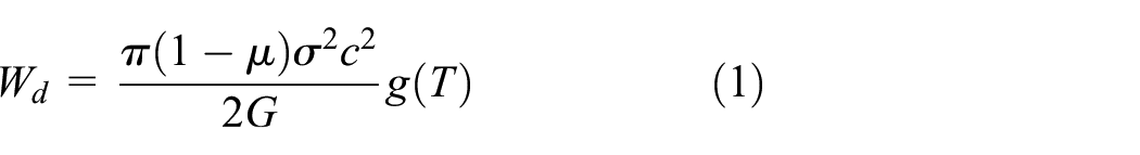
Where,
When the whole energy surpasses the cohesion energy, the crack nucleates. According to the balancing energy of the nucleation, the variation of dislocation energy is in direct proportion to the variation of the superficial area of crack, which can be expressed as follows:

Where,
The width of the crack is set as unit 1, the length is set as a, then:

The equation is written as differential formation 26 :

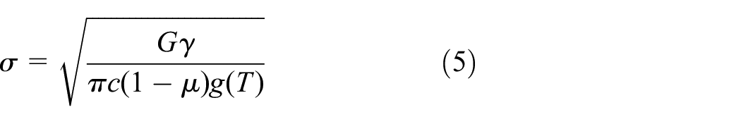
It is supposed that the dislocation pile-up area is the nucleation area of crack and the enlargement of the pile-up area will produce the micro-crack. Suppose dc is similar to da in order to simplify the analysis. 26 The equation (1) is brought into equation (4), it can be obtained the critical dislocation stress is:
Then the critical dislocation stress is brought into equation (1), the critical dislocation energy is obtained:

When the actual energy surpasses the critical dislocation energy, it can be judged that the micro-crack is generated according to the theory of dislocation pile-up.
Whole dislocation energy
Then the dislocation energy with the same unit of grinding hardening will be calculated. The effective stress of grinding hardening is calculated by the classical thermal-stress coupling method of grinding.27–29 The establishment is briefly introduced as follows.
The basic data of material varying with temperature is input into the simulation model which contains specific heat, heat conductivity coefficient, elastic modulus, and coefficient of linear expansion. The boundary condition in the contacting area between grinding wheel and workpiece is the heat source strength applied. The heat source strength of the other surface is 0. Heat convection between workpiece and air is ignored and its coefficient is set as 0. The heat resource is taken as parabola model. And the APDL circulation method is used to realize the loading of grinding heat which moves along the workpiece. The first heat flow q1 is loaded at the first position of the workpiece in the model within a tiny period of time. The next heat flow q2 is moved onto the next adjacent position during the next tiny period of time. The last calculation result is taken as the initial condition for the next calculation. The circulation goes on in this way until the ql moves the grinding heat resource along the direction of feeding. After all heat flow is loaded and the grinding thermal is calculated, the stress-strain field of grinding is simulated based on the results of thermal field and the overall thermal-mechanical coupling simulation of grinding is carried on. The thermal unit is transferred into the structural unit based on the thermal result. The grinding force is loaded onto the unit.
The key simulation parameters and relations are shown in Table 3.
Key parameters and relations of the ANSYS simulation.

The stress result of grinding
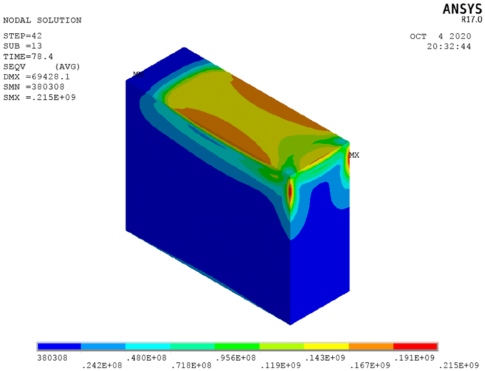
The stress result of grinding (ap = 100 μm, vs = 0.02 m/s).
The factor of temperature in equation (1) is ignored to simplify the analysis. According to the grinding stress

It describes the dislocation energy under the certain grinding condition. In grinding hardening, the surface material is impacted by the abrasive grain, which forms lots of dislocation. And then dislocation energy is generated.
During grinding hardening process, martensite transformation happens in the surface layer of workpiece and the hardening effect reveals. When martensite generates from austenite, the variation energy influences the total energy and the micro-crack. According to the classical nucleation theory, the energy of the factor is the sum of the increment of interfacial energy due to the formation of new phase interface

Using the basic model,
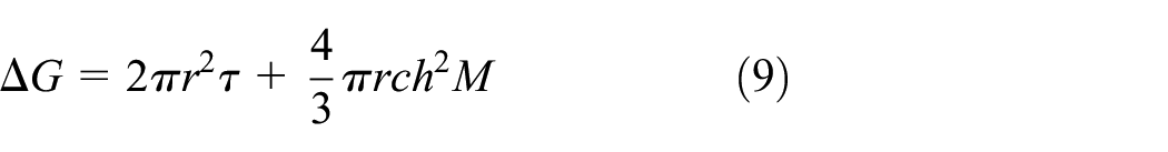
Where,

Therefore, the whole dislocation energy during grinding hardening can be expressed as:

Model and result
According to the result of the critical dislocation energy Wd which is calculated in Section 5.1 and the whole dislocation energy W of grinding hardening which is calculated in Section 5.2, the model of micro-crack of grinding hardening can be established. As is analyzed in the former part of the paper, the micro-crack is formed by the accumulation of dislocation pile-up in the condition of grinding hardening. When the pile-up reaches a certain level, the dislocation source is activated, and micro-crack is produced and grows. Considering from the view of energy, the micro-crack is formed because the dislocation energy resulting from the pile-up reaches a certain level. And the level is the critical dislocation energy. When the whole dislocation energy of grinding hardening W surpasses the critical dislocation energy Wd, it can be judged that the micro-crack of grinding hardening is generated. 25 When the W is smaller than Wd, it is judged that there is almost no crack on the surface of workpiece. Therefore, according to the basic relation between the dislocation energy and the micro-crack, the characteristic of micro-crack can be obtained. The dislocation energy serves as the medium of the model of micro-crack. It accords with the analysis of the mechanism of micro-crack which is talked about Section 3.1.
According to equation (2), the concrete relation can be expressed as:

Then the length of micro-crack of grinding hardening can be estimated in the method. Figure 18 shows the micro-crack under different grinding depth and feeding speed.

Estimated length of micro-crack under different grinding conditions.
It can be seen from Figure 18 that micro-crack is generated when the comprehensive effect of grinding depth and feeding speed reaches a certain point and then it increases with the increasing of the comprehensive effect of grinding depth and feeding speed generally. The variation trend corresponds with the actual situation.
The concrete experimental data and the model result of micro-crack are compared in Figure 19. It can be seen that the calculation length of micro-crack of the model is close to the mean value of the experiment and between the maximum value and minimum value of the experimental data, which shows the model is rational.

Contrast between experimental data and the model result under different conditions: (a) under different grinding depth and (b) under different feeding speed.
And the calculation result is close to the maximum value of experiment, especially when the surface has obvious micro-crack. It is because the calculation of the micro-crack is based on the whole energy which can be regarded as the upper limit of the generation of micro-crack in principle. Then certain dislocation energy can make micro-crack reach the length.
In sum, the variation trend of micro-crack of the model is the same as the experimental value. And the concrete calculation value of the model is within the range of the experimental data. The model which is established in the paper can estimate the actual micro-crack of grinding hardening generally.
Conclusions
The micro-damage can be produced on the workpiece surface in grinding hardening process though the surface of workpiece obtains fine machining effect from the macroscopic. The micro-crack will be produced on the workpiece surface when the grinding depth reaches a certain value. It is formed by accumulation of the dislocation pile-up during the grinding hardening process. The degree of micro-crack increases with the increasing of grinding depth nonlinearly due to its accumulation effect and activation condition. When the grinding depth surpasses 150 μm, it increases sharply. The micro-crack is more uniform under larger grinding depth and the influencing factor of grinding depth is prominent. And the micro-crack increases with feeding speed slightly.
The surface melting coating and decarburization both have a close relationship with the temperature of the grinding zone. The thickness of melting coating layer and decarburization layer increase with the increasing of grinding depth. The surface scratch of workpiece surface is produced by the impact and friction with broken abrasive grain. The relevance with micro-crack of these micro damage is revealed. The melting coating area reveals less micro-crack because of its melting and repainting effect. The decarburization promotes the micro-crack. And the surface scratch accelerates the growth of micro-crack.
A model of micro-crack of grinding hardening is established based on the theory of Cottrell’s dislocation pile-up considering the grinding hardening mechanism and parameters. It can predict the condition of micro-crack after grinding hardening generally.
Footnotes
Handling Editor: Chenhui Liang
Declaration of conflicting interests
The author(s) declared no potential conflicts of interest with respect to the research, authorship, and/or publication of this article.
Funding
The author(s) disclosed receipt of the following financial support for the research, authorship, and/or publication of this article: This paper is supported by Fundamental Research Funds for the Central Universities (Grant No. N2003015).