
Abstract
The electro-magnetic suspension (EMS)-based Maglev train, referred as one of the new transport mode, the two important issues are the loss of stability and the nonlinear coupled vibration because of it including suspension controller and control command. In this study, a Maglev train-controller coupled dynamic model is developed to investigate the stability of suspension controller and the coupling vibration, wherein, the tuned mass damper (TMD) control method is applied to avoid Hopf bifurcation phenomenon of the train-switch vibration. The eigenvalue and time integration methods are used to analysis the instability domain. The results demonstrate the proposed dynamic model is able to represent the loss of stability of the coupled vibration, which is comparable to those obtained via the experiments. Using this dynamic model, the dynamic performance and characteristic of the vehicle/switch coupled vibration is investigated, which further contributes to the TMD-based vibration control method for the vibration of the switch beam and the stability of the coupling system.
Introduction
With the development of rail transit, a new type of transportation – magnetic levitation train came out. Because of its high speed, noise-free, safe, and environmental protection features, it has good application prospects, become experts in various countries. The operation speed of the maglev train can reach more than 400 km/h. However this transportation tool has its own problem. For example when it drives on the track, the magnetic levitation vehicle and the interaction of electromagnetic forces between the track, will result in deformation of the track and severe vibration, which can led to the rail suspension air gap change 1 and even affect the dynamic performance of maglev vehicles.
In 2003, Shanghai opened the world’s first commercial high-speed maglev line, 2 which runs back and forth between Longyang Road and Pudong International Airport. The vehicles used on the line are TR-type maglev vehicles developed by Messerschmitt-Boelkow-Blohm (MBB) Company in Germany. This type of maglev adopts the Electromagnetic Levitation principle: the electromagnetic attraction is generated by electromagnets installed on both sides of the levitation bogie and on the guide way, levitating the train and maintaining a rated small gap of about 8–10 mm through active control. 3
Nowadays, it has been already carried out related research work on the vehicle-switch dynamics of magnetic levitation vehicles worldwide.
Fichtner et al. 4 analyzed the power test results of the switch beams of Shanghai maglev vehicles, and concluded that the frequency of severe vibration of the switch was approximately 14.9 Hz, which was not much different from the frequency of adjustment of suspended electromagnetic forces. Dignath et al. 5 established an equivalent multi body system model and a three-dimensional solid finite element model for maglev switch, analyzed the modal parameters of maglev switch, and compared them with test results. Han et al. 6 studied the suspension stability of maglev train vehicles on the maglev switch. Li et al. 7 studied the application of “Y” type electromagnetic switch, with electromagnetic iron instead of permanent magnets. They used the control of the direction of electromagnetic iron current to guide the direction of maglev train operation, and through simulation to optimize the material and structural parameters of the electromagnet, designed the switch provides a reference direction. Liu et al. 8 analyzed the characteristics of electromagnetic and mechanical switch, introduced a complete electromagnetic switch prototype system in detail and then found the magnetic field generated by the electromagnetic iron instead of permanent magnets on the rail. The applicability of the switch was confirmed, which is of great significance for the future development of high temperature magnetic levitation transportation. Espenhahn et al. 9 studied the flux density distribution of permanent magnetic orbits and switchable track types, and found that the match between the two was very high, and the suspension and lateral forces of the two orbital types were measured. According to the vibration phenomenon caused by the magnetic levitation train running at high speed, through the track switch, the model was carried out by LMS company TEST.LAB software. The modal parameters were measured by hammering method and the modal parameters of the track switch structure were studied and analyzed. 10 Gu et al. 11 used ANSYS software to establish the plate unit and beam unit finite element model of the magnetic floating switch beam, analyzed their respective vibration type and inherent frequency, and compared the calculation results, and finally confirmed that the plate unit finite element model was more scientific and reasonable. Besides they used SIMACK multi-body dynamics software simulation to get the dynamic response of the track switch beam. The model and power stability of the rail coupling system of EMS maglev trains are analyzed by Li et al. The speed of the maglev train model and the influence of the main parameters of the model system on the power stability are studied. 1 Tang et al. 12 studied the vibration of the medium- and low-speed magnetic floating switch, and established the coupling vibration model of the maglev train vehicle by using the method of dynamic differential equations. Then they used MATLAB mathematical software to analyze and obtain that the deformation of the switch would affect the control of the vehicle system, which had influence on the stability of the maglev train. According to the resonance problem of maglev vehicle switch beams, the TLMD damper is designed to effectively reduce the coupling vibration between the maglev train and the switch beam by studying the damper damping method of the switch beam. 13 Hao et al. 14 studied the problem of nonlinear system of coupling vibration for the switch of the maglev train, and made a prospect for the research direction of vibration and control of the middle and low speed magnetic switch. In SIMPACK multi-body dynamics software, Miao 15 established a simulation model of magnetic floating vehicle-switch rigid coupling dynamics, and studied that the active beam stiffness had a more obvious effect on the coupling vibration performance of the switch. Yusheng 16 used ANSYS software to establish a model of maglev switch beams, analyzed the basic characteristics of the coupling vibration response of maglev vehicles-switch beams, and found that the damping ratio of switch beam structure was negatively related to vibration response. Xiaohong and Longhua 17 and Xiaohong and Long 18 established the switch-car body coupled model with PID controller and considered 2 and 3 DOFs respectively, and studied its nonlinear vibration and bifurcation behavior.
The EMS-based train, however, similar to the stability of the wheel-rail vehicle,19,20 is still subjected to the loss of stability because of the stability of suspension controller and the time lag caused by the electro-magnetic suspension response for the control command.21,22
As the switch beam compared with the guide way beam, has lower structure damping and stiffness. This is of one weakness in Maglev system. Besides, its natural frequencies are closed to the frequencies of suspension controller. So far the deteriorated vehicle/switch coupled vibrations have been observed on a number of switch area of the EMS Maglev lines. Such coupled vibrations could pose significant influence on the ride comfort and further contribute to the loss of stability of the coupled system.
To resolve this problem in this study, the suspension controller system, train suspension system and switch must be taken into consideration. A Maglev train-controller-switch coupled dynamic model is thus developed to investigate the stability of suspension controller and the coupling vibration based on Xiaohong and Longhua 17 and Xiaohong and Long’s 18 work, moreover, we consider the first three order modals of the beam’s elastic vibration compared with the first main modal in her work. The results demonstrate that the proposed dynamic model can represent the loss of stability of the coupled vibration, which is comparable to those obtained via the experiments. Using the proposed dynamic model, the dynamic characteristics of vehicle/switch coupled vibration is studied, which further contributes to the Tuned Mass Damper (TMD) control method 23 -based vibration control method for the switch beam vibration and the coupling system stability.
Modeling of maglev-controller-switch coupled system
The EMS-based Maglev train is the application of electromagnetic levitation to make it suspend stable on the track, as shown in Figure 1. The suspension control system real-time detects the air-gap between the suspension electromagnet and the rail, and performs closed-loop control, so that the system can resist the geometric irregular disturbance from the track. But the EMS-based suspension system is more sensitive to the track elastic self-vibration. Considering the weight loss of switch, a more lightweight steel track beam is recommended.

The maglev vehicle passing switch, Changsha, China.
The phenomenon occurs frequently because of the structure vibration of the switch beam and the coupling of the self-excited vibration of levitation unit while the vehicle passes the switch. Vehicles and switch beams vibrate violently and then gradually diverge, which may lead to levitation failure and even hitting or sucking the rail. The coupling vibration of the vehicle and the switch beam, which leads to the complex nonlinear vibration phenomenon, is mainly caused by the elastic vibration and the characteristics of the controller.
In order to study the coupling vibration mechanism of maglev vehicle-switch beam, this complex coupling system can be simplified as a single levitation unit and Euler beam model. The schematic of a single levitation unit-switch beam coupled system is shown in Figure 2. The model consists of a levitation unit m, the car body M, the switch beam Mb, and the levitation controller.

Schematic of the electromagnetic levitation system.
The switch beam model
Usually, the switch girder is supported on the base through two points and the length of the girder of the switch is 18.6 m, while the section height of the switch is 1.35 m. Therefore, the main motion of the switch is elastic bending when the vehicle passing through, which demonstrates the motion of the switch meeting to the condition of the Euler-beam. To simplify the computation, the shear and moment of inertia effects can be neglected.
The motion of the switch can be described by the following equation

Where EI is the flexural rigidity,
Obviously, the deflection of the switch beam can be described as a superposition of sinusoidal functions. According to the Segregation variable method, the solution of the homogeneous equation of equation (1) (in another words, let the right of (1) equals zero) is
where

Substituting equations (3) and (2) into equation (1), the switch beam dynamics function can be obtained,

The suspension magnet model
In above,

A levitation unit consists of two electromagnets in series. The relationship between the control voltage U and the current I can be described as,

where, R is the direct current resistance of a single electromagnet.
The suspension control model
The current loop control is given in equation (7) for reducing the time lag.

Where
The PID control method is used to adjust the

where,
The coupled model for the vehicle-switch system
To sum up, define the state variable

In (9), the system has 8 DOFs with considering the first there order modal
Then the dynamical equation can be depicted in (10),


In addition, in order to verify the effect of vibration control method, the coupled multi-body dynamic model has been set up. The model consists of the Maglev train, the suspension controller and the switch, is established, as shown in Figure 3. In the model, the nonlinearity of vehicle suspension is also taken into consideration to investigate the effects of suspension nonlinearity on the stability of vehicle/switch system. The suspension controller model, including the electro-magnetic suspension model and the suspension strategy, is developed on the basis of PID control theory, which can be described through the equations (5)–(8). Considering the large interaction forces between the vehicle and the switch could excite some vibration modes of the switch system, the flexibility of switch beam is modeled24–26 via the modal superposition method. The vibration modes of the switch are calculated via simulation of the finite element model. The considered maximum frequency of the switch beam occurs at the frequency about 900 Hz.

Vehicle-switch beam-controller coupled model.
Nonlinear coupled vibration of vehicle/switch system
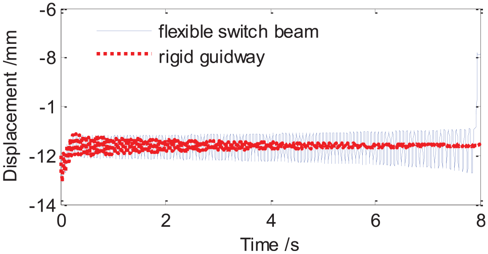
The main elements of the nonlinear coupled vibration of the vehicle/switch system are probably attributed to the flexibility of switch and the low damping in the switch structure. The coupled system may lose the stability when the natural frequency of bogies and guideway gets too close to each other. Owing to such instability, the levitation air gap tends to be unstable, 21 as shown in Figure 4. Using the proposed model, the stability of levitation air gap is investigated considering the flexible switch and the rigid guide way, as shown in Figures 5 and 6. The results show that the variations of levitation air gap converge gradually on the rigid guideway, while the levitation air gap shows unstable fluctuations on the flexible switch owing to the flexible deformation of the switch beam, which is similar to those reported by Han et al. 21 It further indicates the elastic deformations of witch beam strongly affect the stability of the system, which can be observed through the elastic deformation responses of switch beam at the middle span when the system loses the stability, as shown in Figure 7.

Tested air gap reported in reference.
Simulated air gap.

Bogie frame phase trajectory.
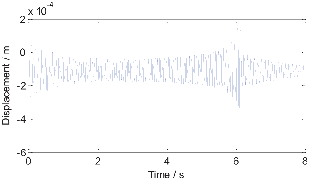
Switch beam vibration displacement.
Figure 8 gives the coupled vibration bifurcation diagram when the maglev vehicle passes through the switch beam and the rigid guideway. The vibration stability of the suspension module changes with the changing of the control parameter kp, whether it is the turn beam or the rigid track beam. For a rigid guide way, when the value of kp is smaller than 12, the suspension module will oscillate at about 4 Hz. When the value of kp is in the range of 52–55, the suspension module will have the limit cycle vibration at the frequency 15–25 Hz or in other words, the Hopf bifurcation occurs, 27 but while the value of kp is greater than 55, the suspension module vibration and divergence until suspension failed. When kp is in the range of 12–52, the suspension unit can be suspended in the vicinity of the equilibrium position, no vibration occurs. As For the elastic switch beam, when the control parameter kp is in the range of 31–52, the limit cycle vibration appears and its amplitude is about 5 mm. The vibration frequency is consistent with the natural frequency of the checkout beam. It can be seen that the switch beam will cause the stability range of the suspension control system parameter to decrease. Even under the rigid guide way conditions, the control parameters is in a stable state, but under the elastic track beam, the periodic vibration may also happen.

Bifurcation diagram of the maglev vehicle-switch beam couple vibration.
The coupled vibration reducing of the vehicle/switch
The vehicle/switch coupled vibration is one kind of self-exciting vibration with the fixed dominating frequency. According to the analysis above, the elasticity of the switch beam which makes the upper range value of the suspend stable domain decreases is the fundamental cause of the coupled vibration. Specifically, the frequency of the elastic vibration of the switch beam is closer to that of the suspend system and the structural damping is insufficient. The vibration of the switch beam behaves as resonant. Therefore, one way to control the vehicle-switch coupled vibration is the vibration reduction of the structural resonant, the principle of which is to cut off the coupled path between the beam and the suspend system. As it is known, TMD is an effective way to control the resonant. But it has rare application in maglev control.
This chapter investigates the influence of the TMD method on the control effect. Because the main modal of the beam is the first order bending, the TMD is located at the center of switch beam, as shown in Figure 9.

The principle for the TMD vibration absorption.
Set the control parameters

Vibration displacement of bogie frame.
The effects of proposed TMD on the coupled vibration is demonstrated through the simulation of vehicle/switch coupled dynamic model considering different TMD parameters, as shown in Figure 10. In condition with TMD (500 and 1000 kg), the air gaps converge to the stable periodical solution with the amplitude 0.2 and 0.16 mm respectively. However, in condition without TMD, the air gap is divergent which is not safe.
The results (Figure 10) demonstrate that the proposed TDM can effectively improve the stability of the system, especially contributing to the stability of the levitation air gap. Therefore the TDM mass has significant influence on the stability of the coupled system, especially, the heavier the mass of TMD is, the better the suspend stability of the system has.
Conclusion
This work mainly focuses on two issues, the nonlinear coupling vibration and the stability of suspension control of the Maglev train-controller coupled dynamic model.
Firstly, the coupling simulation model is established with considering structural dynamics and control command. From the simulation results above, it show the reappearance of the three behaviors which are steady suspension, self excited vibration, and suspension lock. It can be seen the control parameter kp is sensitive to the suspension vibration amplitude. The stable domain of kp for rigid guideway is [1.195, 5.21] × 104 and for flexible switch beam is [1.195, 3.05] × 104. When kp∈[3.05, 5.21] × 104, the maglev vehicle is stable when it passes through the rigid guideway meanwhile the Hopf bifurcation occurs when it passes through the switch.
Secondly as for the vibration reducing, the TMD technology is applied to the vehicle/switch system. With TMD, the air gap can keep stable periodical solution, but without it, the air gap will be divergent to large amplitude.
Footnotes
Acknowledgements
We are grateful to the editor and reviewers for their valuable comments and suggestions that greatly improved the presentation of this paper.
Handling Editor: James Baldwin
Author contributions
All authors contributed equally to the writing of this paper. All authors read and approved the final manuscript.
Declaration of conflicting interests
The author(s) declared no potential conflicts of interest with respect to the research, authorship, and/or publication of this article.
Funding
The author(s) disclosed receipt of the following financial support for the research, authorship, and/or publication of this article: This work has been supported by grant from the (1) National Natural Science Foundation of China (No.11802041). (2) China Postdoctoral Science Foundation (No.2020M683367). (3) Educational Scientific Research Plan of Chengdu Bureau of Education (No.CY2020ZW02).
Availability of data and materials
The datasets used or analyzed during the current study are available from the corresponding author on reasonable request.