
Abstract
In this paper, a more computationally convenient singularity condition of the enveloped surface is proposed using the theory of linear algebra. Its preconditions are only the tangential vector of the enveloping surface, the relative velocity vector, and the total differential of the meshing function. It avoids calculating the curvature parameters of the enveloping surface. It is proved that the singularity conditions of enveloped surface from different references are equivalent to each other and the relational equations among them are obtained. The curvature interference theory for the involute worm drive is established using the proposed singularity condition. The equation for the singularity trajectory is obtained. The calculation method for the singularity trajectory is proposed and its numerical result is obtained. The influence of the design parameters on the singularity trajectory is studied using the proposed curvature interference theory. The study results show that the risk of curvature interference is high when the transmission ratio is too small, especially in the case of the single-threaded worm and large modulus. The proposed singularity condition can also be applied to study the curvature interference mechanism in other types of the worm drive and to study the undercutting mechanism when machining the worm drive.
Keywords
Introduction
The machining and meshing processes of the gears are essentially the enveloping process. The tooth surface of the driving gear is usually considered to be the enveloping surface, and the tooth surface of the driven gear is the enveloped surface. The enveloping theory has been studied in depth in differential geometry, 1 and gear theory.2–5 These studies have shown that the occurrence of singularities on the enveloped tooth surface can lead to the occurrence of the curvature interference during the machining and meshing of the gear pair. The curvature interference can lead to undercutting. Generally speaking, the enveloping surface is the regular surface but the regular points on the enveloping surface can still lead to singularities on the enveloped surface. These singularities can form a smooth curve on the enveloped surface, which is generally the envelope of a family of contact lines on the enveloped surface and is also the edge of regression on the enveloped surface, as demonstrated in Litvin and Fuentes 2 and Wu and Luo 3 . The singularity trajectory will divide the enveloped surface into two branches, which are connected along this singularity trajectory. To avoid the occurrence of singularities on the enveloped surface, it is necessary to use the singularity trajectory to limit the size of the gear blank. It is also due to this feature that the singularity trajectory on the enveloped surface is also known as the curvature interference limit line or the first kind of limit line,3–5.
According to differential geometry, 1 and meshing theory of gear,2–5 at the singularity of the enveloped surface: (i) the normal vector of the enveloped surface is equal to zero; (ii) the tangential vector of the enveloped surface is equal to zero; (iii) the velocity vector of the enveloped surface is equal to zero. However, as these singularity conditions for the enveloped surface are in vector form, they are slightly inconvenient to apply. For this reason, it is common practice to convert it into the scalar form, which makes a further expansion of the singularity condition for the envelope surface.
By associating the vector equation that the velocity vector of the enveloped surface is equal to zero with the full differential of the meshing equation, Litvin and colleagues2,6 transformed the singularity condition in vector form into the problem of the existence of solutions to the overdetermined equation system, i.e. ensuring that the rank of the coefficient matrix of the overdetermined equation system is equal to 2. Then, the singularity condition in vector form can be replaced by a singularity condition in scalar form, that is, the sum of the squares of the three third-order sub-determinants in the coefficient matrix is zero. Using this singularity condition, the singularity problems for the enveloped surfaces of families of two-parameter surfaces and planar parametric curves were studied by Litvin and colleagues7,8. Using the dot product of the velocity vector on the enveloped surface with the normal vector on the action surface, a singularity condition in scalar form of the enveloped surface was obtained in Litvin et al. 9 , which is used to study the singularity trajectory on the face worm-gear of spiroid gear drive. A different scalar form of the singularity condition was derived3,10,11 using the dot product of the normal vector of the enveloped surface and the normal vector of the enveloping surface, which has been applied to the study of the curvature interference theory of machining the involute gears, the spiral bevel gears, and the hypoid gears. Analogously, using the vector equation that the normal vector of the enveloped surface is equal to zero, a similar singularity condition to that in Litvin et al. 6 is obtained in Wu and Luo 3 and Litvin et al. 12 Dong 4 derived the singularity condition for the enveloped surface in scalar form by associating the equation that the tangent vector of the enveloped surface is equal to zero with the full differentiation of the meshing equation and employing Euler and Bertrand formulas, 1 and then he 13 applied this singularity condition to the study of the curvature interference theory for different types of the toroidal worm pairs. Using Dong’s singularity condition, Zhao and Meng14–16 investigated the curvature interference theory of conical surface enveloping the conical worm pair and the ZC1 worm pair. Sohn and Park17,18 studied the geometric interference problem of mismatched cylindrical worm pairs using the separation topology method.
However, in practice, it was found to be complicated to calculate the singularity trajectories on the enveloped surface using the three scalar forms of the singularity condition obtained.6–11. The numerical results and the equations of the singularity trajectories of the enveloped surfaces in the numerical examples are also not obtained in these references. Although the physical meaning of the singularity condition for the enveloped surface given by Dong 4 is clear and easy to calculate, the normal curvature and the geodesic torsion of the enveloped surface need to be calculated when applying this method. Several simplified methods for calculating the normal curvature and the geodesic torsion of the enveloped surface are provided by Zhao and Zhang19,20, but there is still some difficulty in the actual calculation.
Thus, this paper proposes a simpler singularity condition of the enveloped surface, which is inspired by Litvin and Fuentes 2 and Litvin et al. 6 . A rigorous derivation procedure is given using the theory in linear algebra, 21 . This new singularity condition of the enveloped surface avoids calculating the equation that the sum of the squares of the three third-order sub-determinants is equal to zero 2,6and also avoids calculating the normal curvature and the geodesic torsion of the enveloped surface. 4
On the other hand, although these singularity conditions in scalar form of enveloped surface are all derived from the singularity conditions in vector form, the final expressions for these singularity conditions in scalar form are quite different. For example, the singularity conditions presented in Litvin et al.6,9, although they both derive from the singularity condition that the normal vector of the enveloped surface is equal to zero, the final expressions of the singularity conditions in scalar form obtained by them are quite different. However, whether these singularity conditions with different expressions are equivalent and whether there are relationships among these singularity conditions have not been studied in the existing literature in this regard. Thus, this paper studies the equivalence among these singularity conditions of enveloped surface and investigates their relationships.
To illustrate the application of the singularity condition for the enveloped surface proposed in this paper, the involute worm drive is taken as an example. For this purpose, a brief introduction to the involute worm drive is required. As reported in Crosher 22 , the involute worm drive was patented in 1915 by F.J. Bostock, who was an assistant plant manager at David Brown. During the meshing of the involute worm drive, the involute worm tooth surface is the enveloping surface and the worm gear tooth surface is the enveloped surface. The study of the singularity trajectory of the involute worm gear tooth surface has been investigated in Litvin et al. 11 . Although the singularity trajectory on the involute worm gear tooth face is plotted in Litvin et al. 11 , no specific equations for the singularity trajectory on the involute worm gear tooth face have been obtained, nor have specific numerical results been obtained.
Thereupon, this paper uses the newly proposed singularity condition to establish the curvature interference theory of involute worm drive to solve the above problems. The calculation method of the singularity trajectory on the worm gear tooth surface is proposed. The nonlinear systems of equations encountered in the course of the study will be determined using the elimination method and the geometric construction 23 to determine the existence of solutions as well as the iterative initial values. The influences of the design parameters, such as modulus, transmission ratio, and the number of worm threads, on the singularity path of the worm gear tooth surface are studied employing numerical examples.
Theoretical study for determination method of singularities on enveloped surface
Notation
As shown in Figure 1, two unit orthogonal rotating frames
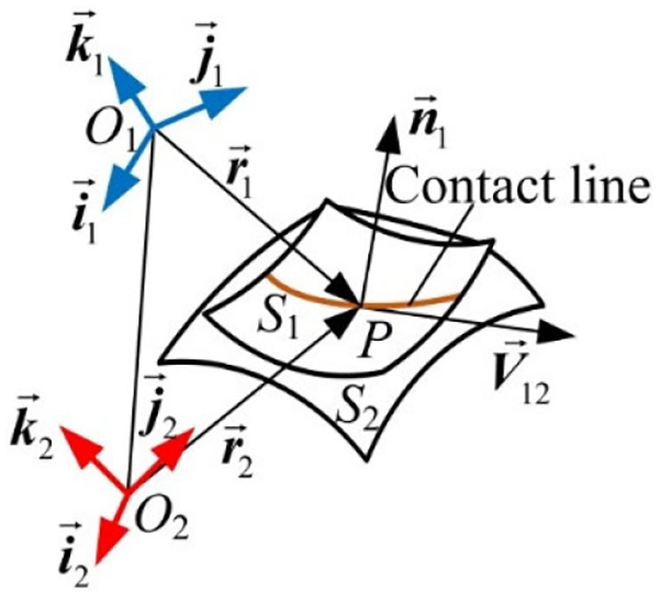
Schematic diagram of gear pair.
Generally speaking, the tooth surface S1 is the regular one. In the frame

where u and
Differentiating equation (1) with respect to u and

From equation (2), the unit normal vector

where
Since the tooth surface S1 is the regular one, the unit normal vector
The relative velocity vector of the gear pair at the contact point P can be expressed as

When the driving gear rotates around its axis with the angular velocity

where the symbols u,
Singularity conditions for enveloped surface
Since the enveloping surface S1 is the regular one, the partial derivatives of the meshing function,

which indicates that the parametric curves on the enveloped surface S2 are the u-line and
From equation (6), the two tangent vectors of the enveloped surface S2 along each of these two parametric curves can be calculated as

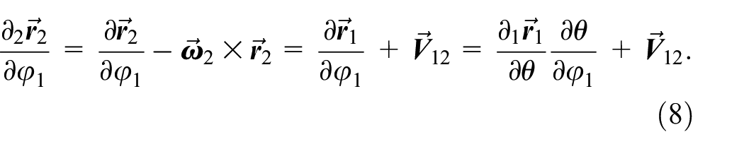
On the premise of

From equation (9), it can be obtained as

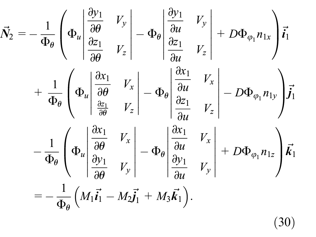
After substituting equation (10) into the two tangent vectors of the enveloped surface S2 in equation (7), a normal vector of the enveloped surface S2 can be calculated as

When the normal vector
When the normal vector

The singularity condition for the enveloped surface S2 in equation (12) is derived on the premise of
Next, the singularity conditions in scalar form of the enveloped surface S2 derived from these singularity conditions in vector form will be discussed. Since the singularity condition for the enveloped surface S2 in equation (12) contains the vector equation

If the determinant on the right-hand side of equation (13) is equal to

Furthermore, since the tangent vector
Litvin and collegues 2,6 proposed that at the singularity of the enveloped surface S2, the velocity vector
Similarly, since the singularity condition in equation (15) is represented in vector form, it is inconvenient to apply. Thereupon, in Dong
4
, firstly, the tangent vector
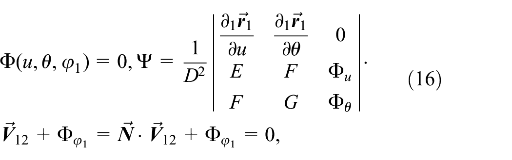
where the normal vector
Establishment of new singularity condition for enveloped surface
After the discussion in the previous section, in practice, the singularity conditions, equations (14) and (16), inevitably require the calculation of the coefficients, E, F and G, of the first fundamental form for the enveloping surface S1.2–5,9,10 In particular, to simplify the calculation of the normal vector
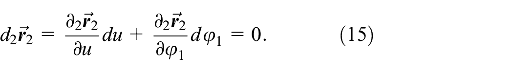
First, the equation of the enveloped surface S2 in equation (6) is differentiated to obtain its tangent vector

which can be regarded as a homogeneous system of linear equations with three unknowns
From equation (17), its coefficient matrix is
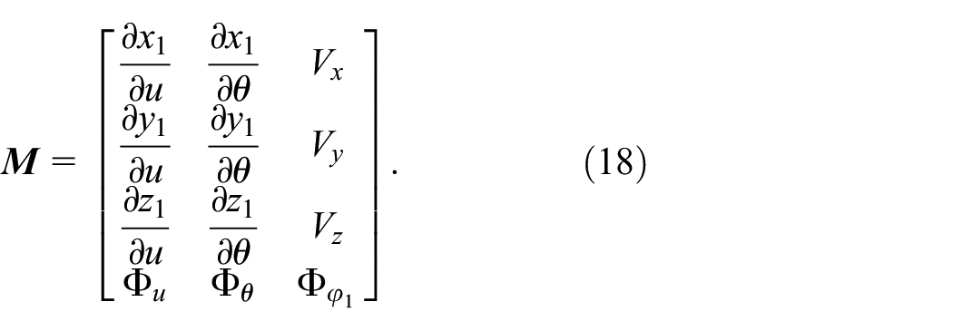
It can be seen from equation (17) that the rank of its augmented matrix is the rank of its coefficient matrix
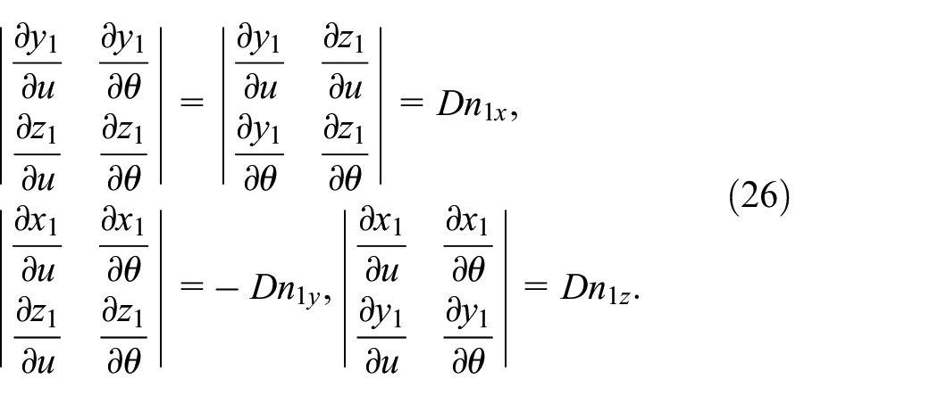
Next, from the coefficient matrix


From equations (19)–(22), it can be seen that the three sub-determinants
By multiplying
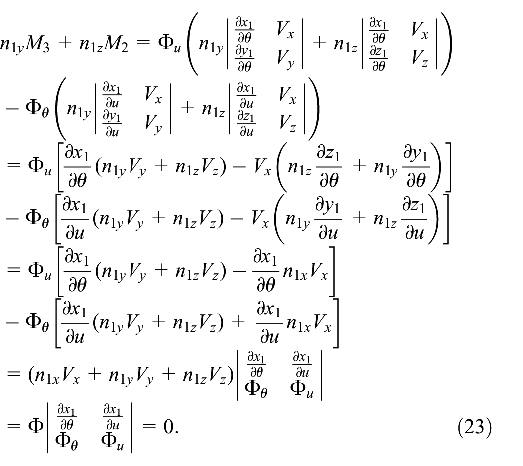
After the derivation of equation (23), it can be seen that there is a linear relationship between the third-order sub-determinants

which illustrates that there are linear relationships between these third-order sub-determinants

which shows that if one of the three third-order determinants
The form of existence of singularities on the enveloped surface S2 will be discussed as follows. Firstly, the singularities on the enveloped surface S2 may be an isolated point or they may form a continuous smooth curve. For example, the cone surface, which is enveloped surface of a one-parameter family of planes, has a cone vertex that is an isolated singularity.
1
When the singularity of the enveloped surface S2 is an isolated singularity, equation (17) should have a unique solution, which indicates that the rank of the coefficient matrix
Secondly, when the singularities on the enveloped surface S2 form a smooth continuous curve, equation (17) should have infinitely many solutions. Therefore, according to linear algebra,
21
the rank of the coefficient matrix of equation (18) should be less than or equal to 2, i.e.
Since there are no singularities on the enveloping surface S1, its normal vector

Since the direct calculation of the rank of the coefficient matrix
Based on the above theory, since there are no singularities on the enveloping surface S1, the normal vector
Similarly to this section, equation (17) has been derived in Litvin and Fuentes
2
and Litvin et al.
6
based on the singularity condition
By comparison, this section differs from the Litvin and collegues2,6–9 in that: firstly, it is on the premise of the singularity condition
Consistency of singularity conditions
The singularity conditions in scalar form, equations (14) and (16), of the enveloped surface S2 have been derived2–5,9,10 using the same techniques as in Section 2.2. However, it is difficult to judge directly whether these singularity conditions are equivalent since there are significant formal differences among the functions
Using the properties of determinant,
21
the function

After the derivation in equation (29), it can be seen that the relationship between the functions
Then, to investigate the relationship between the singularity condition in equation (28) and other forms of singularity conditions, firstly, the expression for the normal vector
After the derivation in equation (30), it can be found that the three components of the normal vector
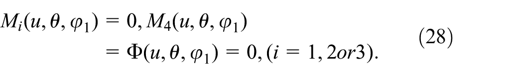
Thereupon, substituting the new expression for the normal vector

which illustrates that when the singularity condition in equation (28) holds,

In summary, this section further simplifies the function
Summary of singularity conditions for enveloped surface

Curvature interference theory of involute worm drive
The worm gear of an involute worm drive is usually formed by a cylindrical hob which has the same generating surface as the tooth surface of the matching involute worm. The working process of the involute worm gear reproduces exactly the process of its formation, and therefore this study does not distinguish between the cutting engagement of the involute worm gear and the working mesh of the corresponding involute worm drive.
Equation of involute worm tooth surface and its characteristic parameters
As shown in Figure 2, a unit orthogonal rotation frame

Schematic of involute helical surface S1.
The cross-sectional shape,
According to the above geometric relationship, the radius vector of an arbitrary point P on the involute helical surface S1 can be represented as
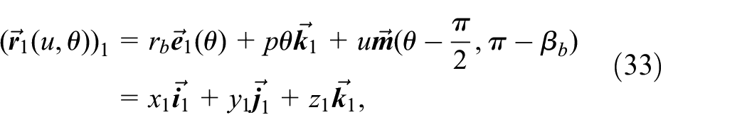
where
Because the involute helical surface S1 is a ruled surface, the tangent line, BD, of the base cylinder is the straight generatrix of the involute helical surface S1. If letting
According to the operational rules of the vector functions,
4
two partial derivative vectors of

Then, from equation (34), the coefficients of the first kind of fundamental form which is also called the first kind of fundamental quantities 1 of the involute helical surface S1 can be worked out as

where
Again, from equation (35), the unit normal vector,

where the coefficients
Herein, this paper specifies that the direction along with the sphere vector function
Meshing equation and equation of worm gear tooth surface
As shown in Figure 3, two unit right-handed orthogonal stationary frames,

(a) Coordinate system setting on involute worm pair and (b) schematic diagram of coordinate system and relative motion.
Two unit orthogonal rotating frames,
When the involute worm rotates around its axis

where
In general, we can assume that the involute worm rotates around the axis

From equation (38), the relative angular velocity vector of the worm pair can be obtained in

Since the angular velocity of the worm is


By definition, 4 , the meshing function of the involute worm drive can be worked out by equations (36) and (40) as

where the coefficients
From equations (37) and (41), the equation of the worm gear tooth surface S2 can be obtained in
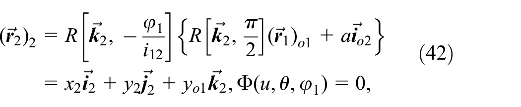
where the coefficients
In equation (42), there is a relationship among the three variables u,
Equation of singularity trajectory on worm gear tooth surface
To determine the singularity trajectory on the worm gear tooth surface, firstly, this section will establish the singularity condition for the worm gear tooth surfaces based on the singularity condition in equation (28) proposed in Section 2.3. Accordingly, differentiating equation (41) with respect to u,


Secondly, from equation (36), all components of the normal vector

To theoretically check the correctness of the singularity condition in equation (46) for the worm gear tooth surface obtained by applying the proposed singularity condition in equation (28), the singularity condition for the worm gear tooth face is again derived in the following using the singularity condition in equation (16) proposed in the Dong 4 . The steps are as follows.
Substituting equations (33), (34), (43), and (44) into the equation for the normal vector

After substituting equations (40), (45) and (47) into singularity condition

With the help of the components

The derivation of equation (49) shows that the third-order sub-determinant
Thus, from equation (42) and (46), the equation for the singularity trajectory of the worm gear tooth surface can be obtained as

The last two equations of equation (50) show that there is a relationship between the three variables u,
Calculation method of singularity trajectory on worm gear tooth surface
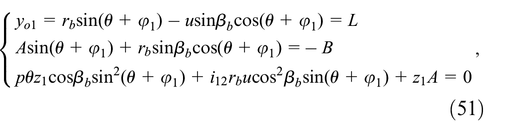
In Figure 4, the coordinate

Schematic diagram of coordinate system of worm gear tooth surface.
where the symbol L is a constant and its range is
To solve the ternary non-linear equation system in equation (51), the elimination method and the geometric construction method 23 are applied in this paper.
Combining the first and second equations in equation (51), the trigonometric functions

where
According to trigonometric identity, it can be obtained from equation (52) as

Let
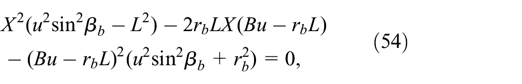
which is a quadratic equation with respect to the unknown
When

where the coefficient
Then, due to

Thus from equation (56) and
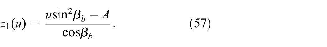
Substituting equations (52) and (55)–(57) into the third equation in equation (51) yields

where the coefficient
Since

To solve the singularity trajectory, the initial values of the iterations of the variable u can be first determined by the geometric construction technique.
23
Secondly, after iteratively solving for the value of u, the values of the variables
Numerical examples and analysis
Parameters of involute worm drive in numerical example
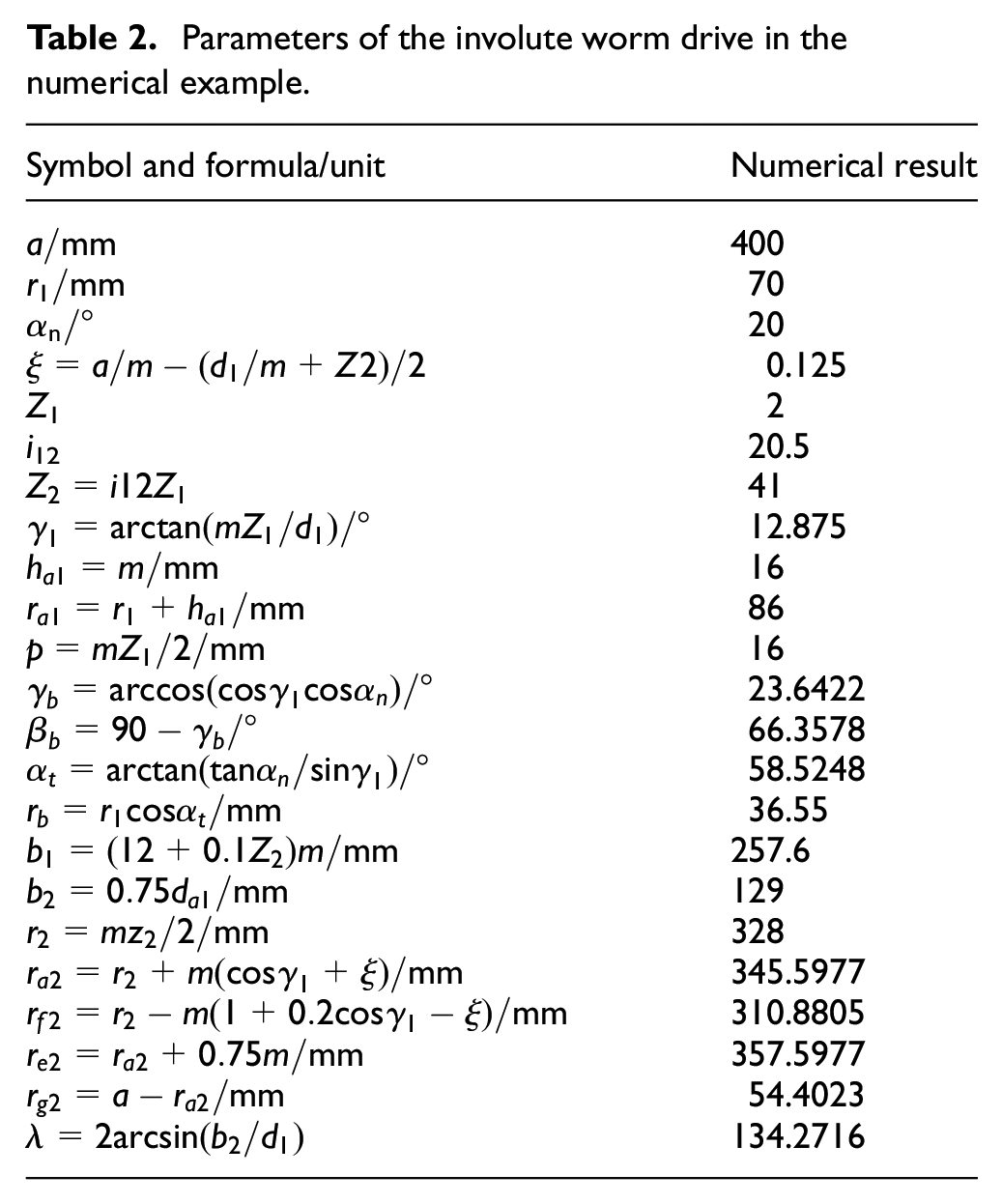
A numerical example of the right-handed involute worm drive is taken as an example to illustrate the specific calculation procedure for the singularity trajectory of the worm gear tooth surface. The numerical results of the basic parameters of the right-handed involute worm drive are listed in Table 2. To determine the basic parameters of the worm drive, the center distance, the number of the worm threads, and the transmission ratio should be determined, firstly. Then, according to the empirical formulas 24 shown in Table 2, the pitch circle radius and the modulus of the worm can be reasonably determined according to the standard values. Finally, the other parameters can be worked out by the formulas listed in Table 2.
Parameters of the involute worm drive in the numerical example.
Numerical computation and results of singularity trajectory on worm gear tooth surface
In this numerical example, the singularity trajectory on the worm gear tooth surface is shown in Figure 5(a). According to equation (38), the unit normal vector of the involute worm is directed from the involute worm solid to space. Based on the geometric relationships in Figure 3, this paper investigates the mesh of the left tooth face of the involute worm with the right tooth face of the worm gear. Thus, based on the coordinate settings in Figure 3, it can be determined that Figure 5(a) depicts the observation result from the gear tooth groove to the worm gear tooth surface.

(a) Singularity trajectories on worm gear tooth surface and (b) conjugate lines of singularity trajectories on axial section of worm.
As shown in Figure 5(a), there are two singularity trajectories on the worm gear tooth surface, which may be called the upper and lower singularity trajectories, respectively. They are represented by the green and red lines, respectively. After determining the boundary dimensions of the worm gear tooth surface, the variation range of the abscissa L can be defined as
In this section, the corresponding singularity when the abscissa
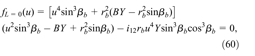
where the coefficient Y in equation (55) is

where
To determine the iterative initial value of equation (60), firstly, using the geometric construction method,
23
two curves

Curves of function
As can be seen from Figure 6, each curve has an intersection point with the horizontal axis, which means that each equation of
Numerical results of singularity trajectory: (a) Numerical results of points Ak, (k = 1, 2 … 12) and (b) Numerical results of points Bk, (k = 1, 2 … 12).

By modifying the value of L, other points
According to equation (36), since the direction of the normal vector
Numerical results of checkpoint

Influence of design parameters on singularity trajectories
In this section, nine numerical examples are given to illustrate the influence of the basic parameters on the singularity trajectory of the worm gear tooth surface, which are denoted by the symbols ①–⑨, respectively. In this section, the center distance of the worm gear pair is fixed as
Design parameters of numerical examples ①–⑨.

As shown in Figure 5(a), the upper singularity trajectory does not cause the curvature interference because the upper singularity trajectory is far from the worm gear tooth surface and does not enter the worm gear tooth surface in these nine numerical examples. However, the lower singularity trajectory is closer to the worm gear dedendum, which indicates that there is a risk of curvature interference near the worm gear dedendum. On the other hand, in the numerical examples, the conjugate lines of the two singularity trajectories do not enter the worm tooth surface. Therefore, the discussion of this section concentrates on the influence of the design parameters on the lower singularity trajectory of the worm gear tooth surface.
In Table 5, Examples ①–⑦ are used to discuss the influence of the transmission ratio and the modulus on the lower singularity trajectory, respectively. The lower singularity trajectories on the worm gear tooth surface of Examples ①–④, ⑤, ⑥, and ⑦ are plotted separately in Figures 7(a) to (d), 8(a), (b) and 9. By observing each of the examples ①–⑦ in Figures 7(a) to (d), 8(a), (b) and 9 individually, with a constant modulus and a constant number of the worm threads, when the calculated modification coefficient of the worm gear is negative after selecting the transmission ratio, the lower singularity trajectory may appear on the worm gear tooth surface, which can lead to curvature interference. Furthermore, when the number of the worm threads is constant, increasing the modulus and decreasing the transmission ratio will cause the lower singularity trajectory to move closer to the worm gear dedendum, which may increase the risk of curvature interference. On the other hand, the horizontal comparison of Examples ①–⑦ shows that when the number of worm threads is constant and the modulus increases and the transmission ratio decreases, the lower singularity trajectory gradually moves closer to the worm gear dedendum. When the modulus is too large and the transmission ratio is too small, the lower singularity trajectory may enter the worm gear tooth surface, which can lead to the occurrence of the curvature interference during the meshing of the involute worm drive.
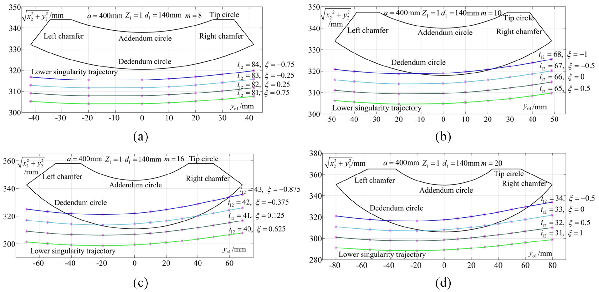
Influence of transmission ratio and modulus on lower singularity trajectory when worm threads

Influence of transmission ratio and modulus on lower singularity trajectory when worm threads

Influence of transmission ratio and modulus on lower singularity trajectory when worm threads
Examples ⑧ and ⑨ are used to discuss the influence of the number of worm threads on the lower singularity trajectory. The lower singularity trajectories of the worm gear tooth surface of Examples ⑧ and ⑨ are plotted in Figure 10(a) and (b). By observing Figure 10(a), when the modulus and the teeth number of worm gear are constant, increasing the number of worm threads can make the lower singularity trajectory be moved away from the worm gear dedendum. From Example ⑨ in Figure 10(b), when the transmission ratio is constant and the number of worm threads decreases and the modulus increases, the lower singularity trajectory will move closer to the worm gear tooth surface, which increases the risk of curvature interference in involute worm pair.

Influence of number of worm threads and transmission ratio on lower singularity trajectory: (a) constant transmission ratio and modulus and (b) constant transmission ratio.
In conclusion, the influence of the basic design parameters on the lower singularity trajectory can be summarized as follows: (1) when the ratio of the worm drive is too small, especially in the case of the single-threaded worm and the large modulus, there is a greater risk of the curvature interference; (2) the risk of curvature interference is reduced when the number of worm heads is more; (3) the smaller the calculated result of the modification coefficient, especially if the modification coefficient is negative, the greater the risk of curvature interference, and conversely the less risk.
In a word, when the design parameters are reasonably selected using the gear handbook, 24 the singularity trajectory will not enter the worm gear tooth surface, meaning that there is no curvature interference in the involute worm pair. Besides, an important finding is that the larger the absolute value of the negative modification coefficient, the greater the risk of curvature interference occurring. Thus, after the basic parameters of the involute worm gearing have been selected, the possibility of curvature interference for the involute worm pair can be initially judged by calculating the modification coefficient. If further precision is required to determine whether there is curvature interference, the singularity trajectory of the worm gear tooth surface can be solved to determine whether the entire worm gear tooth surface is in the non-interference zone according to the curvature interference theory for the involute worm drive proposed in Section 3. The singularity condition of the enveloped surface presented in Section 2 can also be used to study the curvature interference theory of other types of the worm drive. Furthermore, the singularity condition presented in Section 2 can also be used to determine the singularity trajectory when machining the worm and the worm gears as a means of determining whether undercutting has occurred or not.
Conclusions
In this paper, a simpler form and more computationally convenient singularity condition of the enveloped surface is proposed using the theory of linear algebra. The pre-conditions for this new singularity condition of the enveloped surface are the components of the tangent vector of the enveloping surface, the relative velocity vector, and the total differential of the meshing function. It is then sufficient to calculate a third-order determinant containing these pre-conditions. It avoids calculating the curvature parameters of the enveloping surface. Furthermore, it is proved that the singularity conditions of enveloped surface proposed in different literature are all equivalent although they are of different forms. The equations for the relationship among these singularity conditions are obtained.
The curvature interference theory for the involute worm drive is adequately established using the singularity condition of enveloped surface proposed in this paper. The equations of the tooth surface for the worm and worm gear, the meshing equations, and the equations for the singularity trajectory on the worm gear tooth surface are obtained. The calculation method for the singularity trajectory on the worm gear tooth surface is proposed using the elimination method and the geometric construction method, and the numerical results of the singularity trajectory are obtained. The influence of the design parameters on the singularity trajectory of the worm gear tooth surface is studied using the developed curvature interference theory.
The numerical results of the study show that the risk of curvature interference will be high when the transmission ratio of the involute worm drive is too small. Increasing the number of worm threads and the transmission ratio and reducing the modulus can reduce the risk of curvature interference. The risk of curvature interference is greater when the value of the modification coefficient is smaller, especially if the modification coefficient is negative, and conversely the less risk.
Therefore, this paper proposes that a preliminary judgment of whether the curvature interference occurs during the meshing of the involute worm pair can be made by calculating the modification coefficient. If an accurate determination of the singularity trajectory on the worm gear tooth surface is required, then the curvature interference theory established in this paper can be relied upon. The singularity condition proposed in this paper can also be applied to the study of curvature interference theory for other types of worm drives and the study of undercutting theory during machining the worm and worm gear.
Footnotes
Appendix
Handling editor: James Baldwin
Declaration of conflicting interests
The author(s) declared no potential conflicts of interest with respect to the research, authorship, and/or publication of this article.
Funding
The author(s) disclosed receipt of the following financial support for the research, authorship, and/or publication of this article: This study was funded by the National Natural Science Foundation of China (52075083) and the Open Fund of the Key Laboratory for Metallurgical Equipment and Control of Ministry of Education in Wuhan University of Science and Technology (MECOF2020B03 and 2018B05).