
Abstract
The development of a navigation system for autonomous robotic sailing is a particularly challenging task since the sailboat robot uses unpredictable wind forces for its propulsion besides working in a highly nonlinear and harsh environment, the water. Toward solving the problems that appear in this kind of environment, we propose a navigation system which allows the sailboat to reach any desired target points in its working environment. This navigation system consists of a low-level heading controller and a short-term path planner for situations against the wind. For the low-level heading controller, a gain-scheduling proportional-integral (GS-PI) controller is shown to better describe the nonlinearities inherent to the sailboat movement. The gain-scheduling-PI consists of a table that contains the best control parameters that are learned/defined for a particular maneuver and perform the scheduling according to each situation. The idea is to design specialized controllers which meet the specific control objectives of each application. For achieving short-term path-planned targets, a new approach for optimization of the tacking maneuvering to reach targets against the wind is also proposed. This method takes into account two tacking parameters: the side distance available for the maneuvering and the desired sailboat heading when tacking. An optimization method based on genetic algorithm is used in order to find satisfactory upwind paths. Results of various experiments verify the validity and robustness of the developed methods and navigation system.
Keywords
Introduction
The main advantage of using sailboat robots is their applicability in long-term missions, operating autonomously on water surfaces during weeks or months without a human operator. Also, it can be added the simplicity of their hardware solutions, which must be projected based on green robotics paradigms, using low-cost and low-consuming energy platforms. Conventional motorized unmanned surface vehicles (USVs) are normally propelled by fuel or electricity powered propeller spending the most part of their onboard energy with the propulsion system. Nonetheless, it is easy to notice that it is a challenging task, with current technology, to develop a motorized USV for long endurance missions (weeks or months) using only screw propellers powered by electrical motors, for example. There is no current technology based on naturally replenished energy, as solar cells, that can allow for this, simply because the consumption of such USV systems is bigger than any onboard power plant can produce using renewable energy. Thus, humans have to intervene or they have to be stopped after a certain time of operation, normally for refuelling or battery recharging. On the other hand, sailboats are wind-propelled, thus spending less energy than required for operation on conventional USV. This feature can be particularly interesting in long-term missions as the recent traverse of the Atlantic Ocean by the Sailbuoy Met (SB Met). 1 Other missions in environment monitoring operations, such as monitoring coral reefs, verifying quality of water, and surveillance of borders can rely on such approach, using sailboats.
There are several open problems yet to be solved related to autonomous robotic sailing. As examples, sealed cases should be used to embark electronic devices, and the sailboat hardware system must have redundant sensors in order to diminish non-systematic errors and also to keep its robustness. Also, the software architecture must be designed to have a controller that is effective, efficient, and robust, in order to allow system operation in variable situations, as the sailboat works in a highly nonlinear, and dynamic ambient that has sudden and undesirable changes, mainly in the wind parameters as its speed and direction. A simple high-level navigation system for autonomous sailboats consists basically of two parts: the path planning (high-level control) and its execution (low-level control).
The development of a low-level controller to guide the sailboat to a desired target is a relatively easy task, usually solved by using simple, with static parameters, proportional-integral-derivative (PID) heading controllers. Since modeling the sailboat dynamics in its full extension is a rather complex task, the use of PID-type controllers facilitates the tuning process, besides being of easy and fast implementation. In general, this is enough to bring the sailboat to a target using a single set of (static) control parameters (Kp, Ki, and/or Kd) throughout the entire mission, which are generally found by trial and error. In fact, such a practical experiments are reported following this simple approach in an RC Monsoon 900, with a simple proportional controller, which has been shown to work experimentally. However, further work has noticed that this approach has some critical limitations specially when the target is against the wind. Notwithstanding the fact that this strategy is easy and simple to implement, the main drawback of a PID control for sailboats is its inability to precisely approximate nonlinear behaviors, especially in tasks with specific constraints such as time and energy. In such cases, the use of a single linear control strategy is ineffective and may result in undesired behaviors. This is the main motivation for our research using GS-PI: It keeps the control strategy and development simple while increasing performance by using multiple linear controllers that are dynamically chosen depending on certain conditions to approximate nonlinear behaviors.
Another remaining challenge is to find an optimal path when the target is directly against the wind, in the area called dead zone. This angular region occurs as a fan of directions, depending on the boat construction, which is about 20° to 30° to one and to another side of the path straight against the wind direction. If a desired point is located in this region of about 40° to 60° around the direction of the wind, the sailboat cannot reach these points by following a straight-line path. This happens because in this situation, the angle of the wind on the sail does not result in a forward force component for any sail position. In conventional sailing, when the sailor (human) wants to reach points that are against the wind, a maneuver consisting of following a zigzag path is performed. This maneuver is called tacking or beating. Optimization of the tacking is an important feature for autonomous sailing once this could drastically decrease the time of the maneuvering. We noticed that the optimization of short-term trajectories for autonomous sailing is not completely solved in the literature, as it will be shown further in this text, thus being also a research focus, and one of the contributions in this article.
The contributions of our work are inside the realm of the navigation systems for autonomous sailing, more specifically we propose strategies for low-level control and short-term path planning. The first major contribution is the use of a GS-like PID control strategy, besides the use of a tuning strategy to find the parameters, which have not been used previously in the literature for autonomous sailing. PID control techniques for robotic sailboats commonly use a single set of parameters (Kp, Ki, Kd) during the whole maneuvering. 2 –7 Simulation tests have shown a gain in performance mainly in narrow maneuvering conditions (water corridors) when compared to control strategies found in the literature. So we demonstrate that the performance can be enhanced when varying these gains during the maneuvering according to the wind and target directions, and we provide a way for determining the best values for these gains.
The second contribution is the use of genetic algorithm (GA) for finding the near optimal, best tacking points. There are previous techniques in the literature for finding reachable tacking points. 8 –10 However, we could not find one that proposes optimization methods for autonomous sailboats to find the best tacking points with respect to several requisites such as time to target reaching, power consumption, or traversed area. In general, these techniques use previous defined parameters, thus finding static tacking parameters that are applied in any situation. These parameters can be the number of zigzags, angle from the target direction, and apart distance from the straight original path line to the target (lateral distance).
In resume, the two main contributions (in the context of sailboat navigation automatic system) are the use of a GS-like strategy for the control and of the model-based optimization for the tacking. The main goal of this work is to improve the overall performance of the sailboat navigation system that, at first instance, consists of both the low-level controller with variant parameters and the short-term trajectory following including performing the tacking if necessary, and its optimization. The combined application of these strategies allow the sailboat to reach desirable, predefined points in the environment with a shorter time or respecting other restrictions.
Related works
There are works in the literature dealing with improved PID control algorithm, which has been applied to the control of motorized autonomous surface vehicles. 11 –13 The most related to ours is the work of Larrazabal and Penas 14 in which a gain-scheduling approach utilizes PID controllers whose tuning parameters have been optimized for trajectory tracking by using a GA, for dealing with the different operation points (GS-PID-GA). That work deals with course control for trajectory tracking of a motorized USV that has active control over its linear velocity by changing the main propeller revolutions per minute (RPM). Applying a similar control strategy to sailboats is nontrivial, since its linear velocity rely on unpredictable wind forces, which translates in a reduction of maneuverability and also makes it harder to follow predefined trajectories. Thus, the main difference of our approach is the project of a control system that meets the movement restrictions of a sailboat by using less strict control objectives and tries to loosely minimize lateral distance from river banks while maintaining a general heading allowing maneuvering on narrow paths.
Related to robotic sailboat projects, we resume the several works that were found in the literature and their control strategies in Table 1. The SB Met (Sailbuoy) 1 listed in the first row of Table 1 deserves our attention because it is the first (and only) USV, to date, to complete an Atlantic crossing, achieved on 26th August, 2018. Leaving fom Newfoundland and arriving at the Ireland coast, the sailboat spent 80 days running totally autonomously at the sea. The sailboat has traveled approximately 5100 km doing kind of a tacking around the straight path to the Ireland coast, which is about 3000 km if considering to follow the (closest) straight-line planned path (on water surface). It is a 100% wind-driven unmanned remotely controlled sailboat, capable of spending up to 6 months on the water, without human intervention, with efficiency of about 50%. It has been used in long-term ocean research. 15 –17 Notice that this relevant event has opened several lines of research, mainly on optimization of the performed path, which is much greater than the traveled distance in the case of a conventional (motorized) boat. The positive issue is the autonomy that the SB Met, as it does not need to use any kind of nonrenewable energy. Regarding control, the only information found is that no sail control is present leading us to understand that only the rudder is controlled, being this done remotely. 1,17 The type of controller is not reported anywhere. The Sailbuoy is self-powered, propelled through a new patent based on the wind, and is operated and controlled remotely by qualified personnel from an operations center. 17
Sailboat projects and their control strategies.

LQR: linear–quadratic regulator; NL: non-linear; PD: proportional-derivative; PI: proportional-integral; PID: proportional-integral-derivative.
In Table 1, the projects Iboat, 18 Roboat 19 and 20 use a fuzzy control strategy for both the rudder and sail control differing from each other only in the pertinence functions chosen in each project. The main goal of applying fuzzy logic to sailboat control is to find rules, based on the knowledge of experienced sailors, that reproduces the sail and rudder’s movement performed by a human during sailing. The Hyraii 21 project uses optimal control techniques in the form of a linear–quadratic regulator (LQR) controller. The VAIMOS 22 project uses a line follower controller, which seeks to keep the sailboat in straight lines established by a higher level navigation system. The remaining researches address the control problem by way of using PID heading controllers. The Avalon 3 project uses two PID controllers in a reference model control scheme. In its first approach, the FASt 2 project found a simple model for sailboats and derived a control law, finding the proportional and integrative parameters of its PI controller. Several projects, such as the Aeolus, 4 the Aland Sailing Robots, 5 the SailBot, 6 and the Kumar proposal 7 set the parameters of their controllers through trial and error experiments. The literature also presents some advanced control strategies applied to sailboats such as nonlinear course control 23 and line following using potential fields. 24
Nonetheless, all of the PID controllers presented in Table 1, and their variations, use static control parameters for the entire movement of the sailboats. Further, it is not specified any type of restriction (time to target, energy consumption, nor side distance) for choosing the right parameters. As explained above, this changing of parameters is attractive mainly because our system works in a highly nonlinear environment that needs a different strategy at each situation of wind. So, following the success of gain-scheduling control strategies in other types of mobile robots
11
–14,25
–29
, we propose to use such approach in this work for the development of the sailboat control system. The proposed method uses experimental data obtained in simulation to decide which controller parameters satisfy specific constraints. For example, if the sailboat goal is to reach the target at the smallest amount of time, that is, the system has a time constraint, our method finds the control parameters that most satisfy such said constraint. We have investigated the hypothesis that using more than one pair of parameters
Works dealing with the upwind situation
Some few references can be found in the literature about short-term path planning and optimization strategies for sailboat navigating against the wind. The strategy adopted to solve this problem can be classified as deterministic or probabilistic. Deterministic strategies make use of locally sensed data (instantaneous) about the wind (as speed and direction) and the boat desired heading to calculate the best path. The probabilistic approach is based on statistics, using the wind probability distribution in order to determine the trajectory that is near the optimum. Some deterministic approaches found can rely on techniques such as potential fields, in which the dead zone (direction against the wind) is treated as a virtual obstacle, 10 or using the polar diagram of the sailboat, which is previously determined, performing by hand annotations of the headings that are optimum given all of the wind directions. 30 Also, there are other strategies that use fixed values for the heading, depending only on the wind direction. 8
Differently from the above strategies that have been, all of them, validated in robotic platforms, the strategies relying on the probabilistic approach have not yet been reported on autonomous robotic sailboats. They are often used in regattas to help sailors to take the best actions given certain weather conditions. Such approaches use Markov decision processes 31,32 and Markov chains 9 for estimating the trajectory that is optimum, helping human sailors to take their decisions.
Work contextualization
The GS-PI heading controller for sailboat robots proposed here uses experimental data obtained in simulation to find near optimal variable control parameters (Kp, Ki) which meet the control objectives of the desired application. This approach differ from the above traditional PID sailboat heading controllers found in literature, which generally use a single (static) set of parameters for all maneuverings. Here we show that the use of a control table that adjusts the control parameters to each maneuvering improves the sailboat performance in each particular application. The other problem addressed here is the short-term path planning method for executing the tacking, allowing to go to targets in the dead zone. Our approach differs from the literature as it introduces a very simple and effective way for executing the tacking. Basically, information about the available area for sailing, the sailboat desired target, and the heading is used to calculate, when necessary, the tacking waypoints from the current position toward the target position. The resulting tacking trajectory is optimized using a GA in a model-based approach. This evolutionary model provides near optima multiple paths, from which the best one can be chosen. This method is implemented and tested using the simulator described next, and it is currently running in the 2.5 m sailboat N-boat II.
Sailboat dynamics and kinematics (with a 4-DOF simulator)
In order to test and verify our proposed methods, we improved a sailboat model developed by researchers of the University of Southern Denmark. 33 This simulator model describes the dynamics of a sailboat with 4-degrees of freedom (DOF), which differs of a traditional sailboat model because it also considers the roll angle. Figure 1 shows the used coordinate system and Table 2 shows the notation adopted in the current work in order to get the simulator to have a behavior as similar as possible to the real version of our robotic sailboat.

General coordinate system for a sailboat.
Adopted notation.

DOF: degrees of freedom.
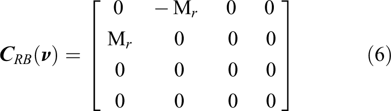
As said, this modified model is currently implemented in Matlab using the Simulink toolbox, with a dynamics and kinematics approach that is approximately (as possible) the one of our real sailboat. The general vector model that represents the sailboat movement is given by

where


The terms


The term


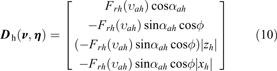
The terms L and D used in equations (9), (20), and (21) are the lift and drag forces, which are respectively given by (equation (12))

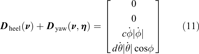
The term

The term


Here, the parameter

The current state-space representation of the sailboat is given by equations (14) and (18). Finally,
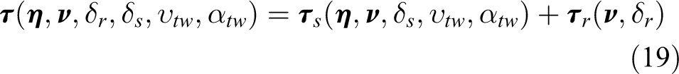


The simulator has a state equation structure, and the sailboat state vector is given by

Visual representation of the sailboat simulator.
As said, the original simulator model developed by Xiao et al. at University of Southern Denmark (USD) 33 has been modified in our work to agree with the requirements of our sailboat project. The first modification that was necessary is to replace the original heading control by the GS-PI controller developed in this work. We also changed the original sailboat parameters to meet the specifications of our sailboat.
The proposed guidance and control system
Different types of applications imply different control objectives. For example, a water quality monitoring mission on a river may require maneuvering in small or narrow areas or respecting some power use requirements where velocity is not a relevant issue. Notice that such restrictions imply that the best path is usually not the fastest path. On the opposite, in a rescue mission, the sailboat must reach the target in the smallest possible time even if this compromises energy management. Long-term missions may require the execution of maneuverings that reduces energy consumption, preserving the robot energy autonomy with self-sufficiency. Thus, the control challenge addressed in this work is the development of a method to find GS-PI low-level controllers for each specific application.
Gain schedule PI control: GS-PI
The idea behind GS-PI is to design specialized controllers that meet the specific restrictions of each application. In this way, a higher level agent can select the best available controller according to the current maneuvering being performed, increasing system efficiency. In the sailboat, the low-level controller must act specifically on the rudder and on the sail to obtain the desired motion. Acting on the sail is simpler, the problem can be summarized in finding an angle within the sail’s movement space, according to the actual wind direction given by the wind sensor. For the rudder, a PI-type heading controller is used due to its simplicity, robustness, and fast implementation. Changes in the proportional and integral parameters modify the rudder behavior and consequently affect the movement of the sailboat. The control problem is then reduced to finding the Kp and Ki parameters of the rudder controller that result in the desired movement of the sailboat according to each application.
The proposed solution consists of finding the best PI controller for a certain application through simulations. Field experiments show that the variables with the highest influence on the movement of the sailboat are the initial orientation (θ) and the wind direction (
The mission of water quality monitoring in rivers is used to test the described method. In this application, the available navigation area is narrow, which implies a smaller area for the execution of the maneuverings. In this case, the controller must keep the sailboat in a safe zone, which may be previously known by a higher level agent looking a map for example or obtained in real time using cameras and/or 3-D sensors. In this situation, a control restriction is to ensure that the sailboat is always inside the safe area. It is then necessary to check the available lateral distance (dl) for navigation when starting a new maneuvering. The proposed solution to this problem is to use a lateral distance restriction, that is, to find the pair (Kp, Ki) that results in the shorter dl.
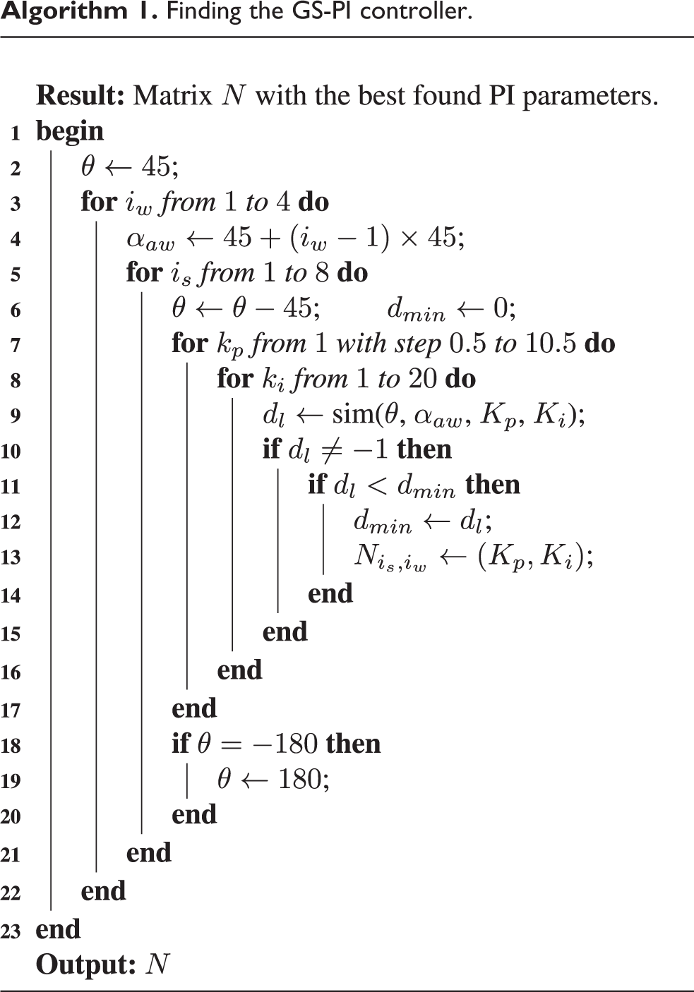
Algorithm 1 presents a possible implementation of the above idea. The loops in lines 3 and 5 generate the initial conditions of the maneuvering, which are represented in the algorithm by variables θ and
Finding the GS-PI controller.

Short-term path planning in upwind situations
In this work, the wind direction can be determined in relation to the sailboat and the target direction using a wind vane sensor. The sailboat direction can simply be determined by way of a compass or a more precise sensor in case of a high-precision mission. Moving the sailboat toward a target position is a question of choosing the best strategy if this target position is not directly against the wind. If the desired position is directly against wind, new waypoints have to be calculated (and optimized) coming up with a zigzag path for the tacking. This new path will be composed of a series of alternated waypoints, to one side and to another side of the straight line defined by the actual sailboat position to the target position, which composes the tacking maneuvering. The amount of waypoints to be used and associated zigzag angles are determined as a function of the surrounding conditions (available area for maneuvering) and on the mission requirements, providing the sailboat navigation to the goal as fast as desired.
This upwind path planning method has to find points in-between and laterally to the straight line linking the actual sailboat position and the desired position, in order for the sailboat to navigate to the target in situations that it is directly against the wind. Our proposal for solving this situation is to create a path planning method that can be used to determine alternated waypoints, in such a way that all of them can be reachable, from one to the next one. This condition is fulfilled if the paths from each of them to the next are outside the dead zone, which implies that they are reachable in straight line. This can be done by choosing appropriate tacking distance dt and orientation
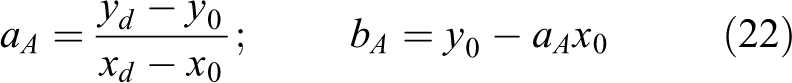
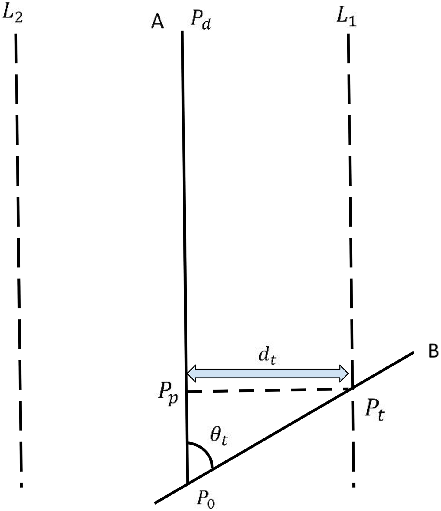
Path planning method illustration, where points
From these, the parameters of the line B, obeying an angle of

A point Pt can then be determined on the line B, respecting a maximum distance dt to line A, which is calculated using Pp and Pt. The coordinates xt and yt of point Pt are used by equation (24) in order to determine the parameters of lines

The number of tacking points is defined by equation (25), that gives the quantity k of steps with size

The X and Y necessary steps for advancing a certain distance

After these initial calculations, all of the tacking point

Notice that by changing the parameters
Short-term path panning method.


Optimization of the tacking approach
Parameters
For the optimization of the tacking, we initially try to describe the function to be optimized through a series of initial experiments. This is done in a straightforward way by varying the values of the parameters (
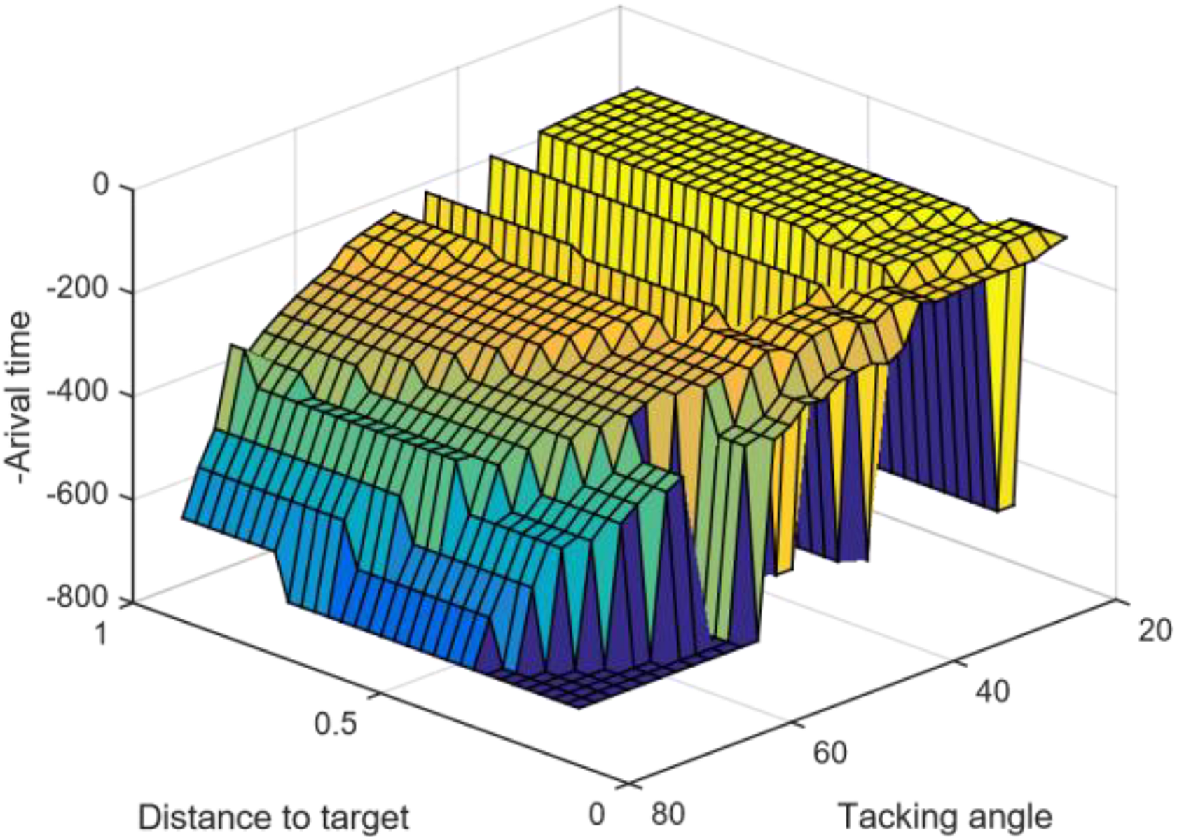
Brute force method graph obtained in simulation with varying parameters dt and
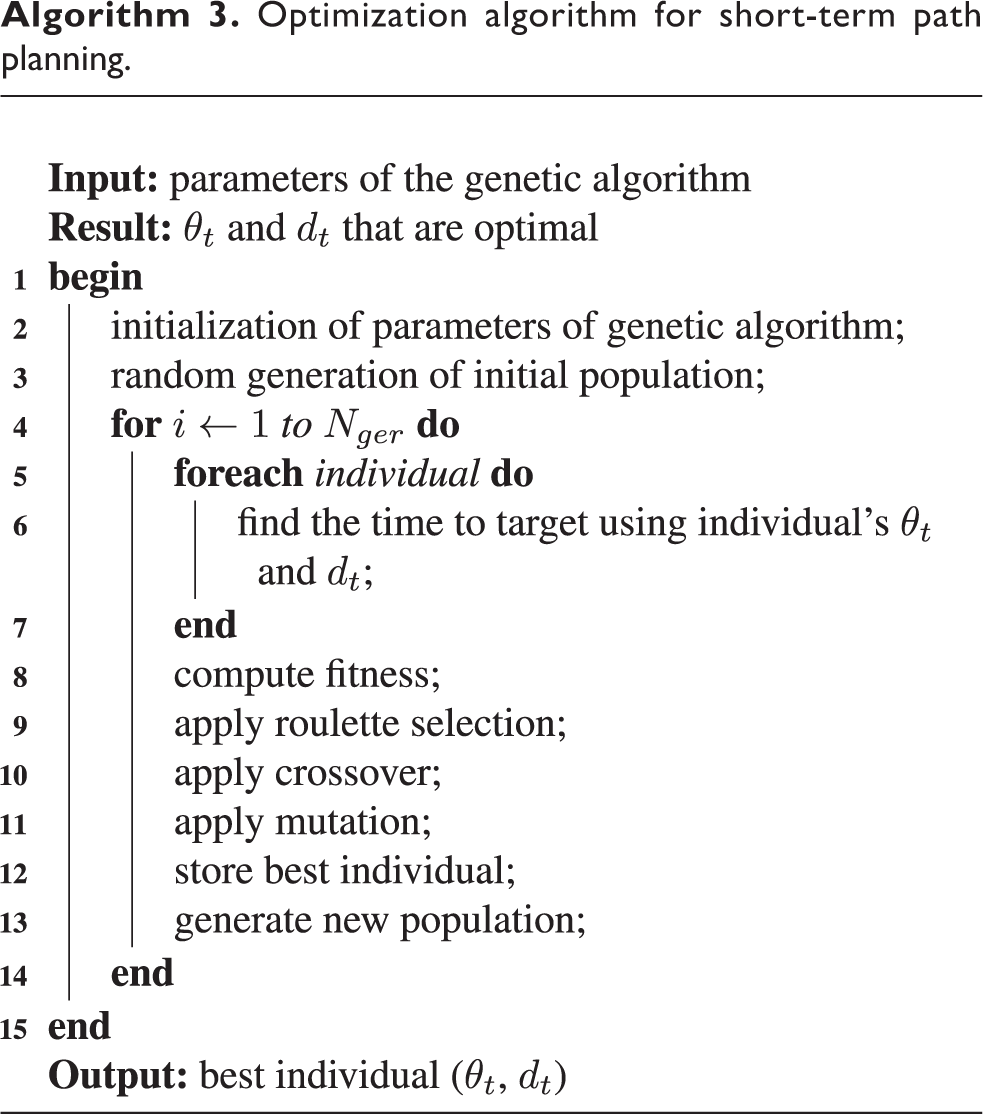
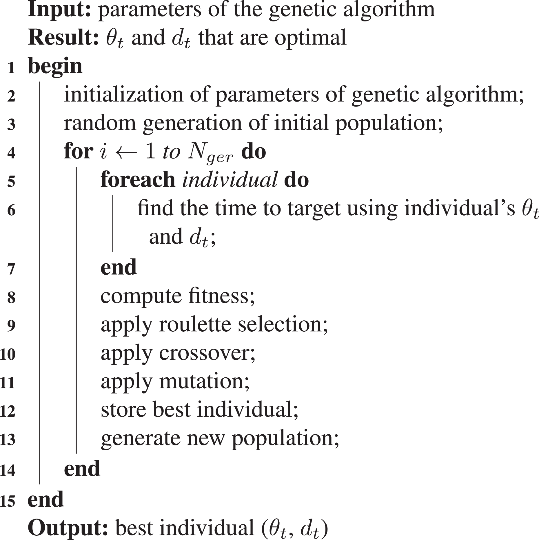
Algorithm 3 implements the idea above, using a traditional GA approach for the short-term path planning optimization. Binary strings represent individuals and they contain values for
Optimization algorithm for short-term path planning.
Experiments and results
The proposed navigation technique, as a whole, is analyzed through a series of experiments, which were planned for verifying and validating both methods devised here. Experimental setups and tests are described next for the GS-PI control approach and for the short-term path planing, respectively.
Experiments with the control system
We performed a series of simulated experiments to test the performance and robustness of the GS-PI when compared with a static PI approach and with a simpler P controller
Finding the static PI controller
For the application of navigation in narrow environments, the worst scenario happens when the wind direction and initial sailboat orientation result in a route with maximum lateral distance. Simulation tests have shown that this is the case when the wind direction is 180° and the initial orientation of the sailboat is 135°. Figure 5 shows the simulation result using the exhaustive search method (brute force). The values of Kp and Ki vary and the maximum lateral distance is obtained for each maneuvering. This experiment shows that for the worst scenario, the minimum lateral distance occurs when

Graphic representation of the results obtained using the exhaustive search method.
Finding the GS-PI controller
The experiment to find the GS-PI controller is similar to the static PI, but now the same experiment is applied for several wind direction and initial sailboat orientations. The problem was then divided into 32 cases: 4 wind directions
Pairs

Discussion
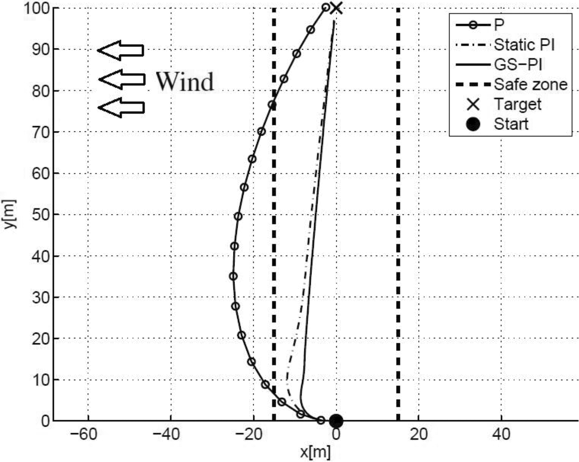
Figures 6 and 7 show the results of the experiments using three control strategies: P, static PI, and GS-PI. The test shown in Figure 6 was performed with wind coming from 180° and initial heading of 45°. In this case, all controllers were able to keep the sailboat within the safe zone, but the GS-PI controller reduced the lateral distance by 46.21% when compared to the static PI controller.

Sailboat path during first control experiment. Initial heading = 45°. Wind direction = 180°.
Sailboat path during second control experiment. Initial heading = −90°. Wind direction = 90°.
Figure 7 shows the result of another experiment carried out, where the wind comes from 90° and the initial orientation of the sailboat is −90°. In this experiment, the controller P was unable to keep the sailboat in the safe zone. Static PI and GS-PI controllers met this requirement, with the GS-PI controller reducing the lateral distance by 27.38% when compared to the static PI controller. In general, the experiments show that the GS-PI controller is the most suitable, among the analyzed controllers, for applications in narrow environments. A size reduction of the GS-PI controller table is also a possibility, since there are some cases in which the initial orientations
Experiments with the short-term path planning
For testing the path planning for upwind situations, without loosing generality, lets set the boat starting point at

Trajectory against wind from simulated experiment with constant dt and varying

Trajectory against wind with 25° wind angle. The black dot is the initial position, black cross is the target position, and the generated tacking points are the black circles. The sailboat trajectory is in blue. The parameters used for the left-hand graph are set as

Simulated experiment with 30 min of duration, in which the low-level control and tacking are fully operating in the navigation system.
Optimizing the path
In the following, we use the GA with the tacking method described above to find near optimal tacking parameters that improve time to target. The performance of this GA approach is compared against a brute force method, which consists of setting the tacking parameters by trial and error similar to what was presented in Figures 8 and 9. To validate this optimization method, we separated the problem in scenarios. The best parameters, which in this scenario are the parameters that result in the minimum time to target, are determined by both methods for each scenario shown in Table 4.
Wind scenarios.

For the brute force method, the parameters
Results obtained by both approaches.


Comparison of brute force with our approach in scenario 2 using the best tacking points found by both approaches. Values for the parameters
Conclusion
A navigation system consisting of both a short-term path planning and a GS-PI-based low-level heading controller is proposed in this work that allows a sailboat robot to reach desired positions autonomously. For the path planning, we apply a deterministic approach for immediate (short-term) path redefinition, and a further optimization by GA, in order to get the best tacking points according to the space available for maneuvering and appropriate navigation angle. Experimental results verify and validate our approach. In all of the experiments with the optimized method, the sailboat was able to reach the final target point. The method is versatile, if we consider that the two parameters (
As a second contribution, we propose to apply a GS strategy to enhance the low-level control, coming up with a new PI control approach not used previously in robotic sailboats. Several pairs of parameters
The data obtained in the simulation experiments confirm the initial hypothesis that the use of a GS-PI controller can improve the sailboat performance, mainly during area constrained missions, when compared to PI controllers that use static parameters. The strategy to find a GS-PI controller introduced in this article can be automated by way of using the mathematical model of a sailboat. The main drawback for the design of a GS-PI controller is to find suitable models that faithfully represent the movement of the sailboat. The implementation of the method developed in the N-Boat II and field trials to investigate the impact that random variables such as water currents and waves have on the movement of the sailboat are possibilities of future work.
Future work, that has already been started, consists on implementing and testing in practice the versions of the methods proposed for this navigation system, in a larger sailboat that has finished its construction. Further tests will be performed in real situations of sailing. This further implementation will allow the reduction of computational complexity that is a necessity for the real-time usage of the developed tools in embedded processors of this larger sailboat robot.
Footnotes
Acknowledgements
We thank Coordination for the Improvement of Higher Education Personnel (CAPES), Brazil, for the grants of Davi Santos under finance code 001, and National Sponsoring Agency for Research (CNPq) for the grants of Luiz Gonçalves.
Declaration of conflicting interests
The author(s) declared no potential conflicts of interest with respect to the research, authorship, and/or publication of this article.
Funding
The author(s) disclosed receipt of the following financial support for the research, authorship, and/or publication of this article: This study was financed by Coordination for the Improvement of Higher Education Personnel (CAPES), Brazil, under finance code 001 and research project number 88887.123914/2015-00.