
Abstract
Friction is the main factor which degrades the control precisions of the servo system. In this paper, a cross coupled control method based on RBF neural network and disturbance observer is proposed for multi-axis servo system with LuGre friction, in order to implement high precision tracking and contouring control. Firstly, a feedback linearization controller is designed to realize the position stable tracking for single-axis motion; then, the disturbance observer is used to observe and compensate the friction. However, in practical application, the observation gain is difficult to select, and it is easy to cause observation error. In order to enhance the tracking accuracy and system robustness, the RBF neural network is introduced to approximate the disturbance observation error online. Finally, the cross coupled control is used to coordinate the motion between the axes to improve the contour accuracy. The simulation results show that the proposed method can effectively compensate the influence of friction on the system, has good tracking accuracy and high contour control precision.
Keywords
Introduction
Multi-axis servo system is widely used in precision machining and other manufacturing fields because of its high speed and high precision.1,2 The main purpose of multi-axis linkage operation is to realize continuous control of tool or workpiece movement in turn or simultaneously in their respective coordinate system according to the command issued by the control system, so as to process parts with complex contour surface. The contour control of servo system is to move along the specified track as accurately as possible. When the specified trajectory is in multi-dimensional space, each feed axis of the system must coordinate to obtain the specified trajectory. Obviously, the contour accuracy of the system depends on the comprehensive motion accuracy of each axis. Different parameters of each axis and mismatching of dynamic characteristics may cause contour error. In the actual operation, any interference of each axis, especially the influence of friction, will affect the contour control performance.
Friction plays an important role in the servo control system, which limits the positioning accuracy of the system and even makes the system unable to run smoothly.3,4 With the development of industrial equipment and technology, the traditional Coulomb friction model can no longer meet the requirements of high-precision control. Scholars began to study and put forward many friction models to describe the internal friction effect of servo, such as, Dahl friction model, Bristle friction model. On the basis of Dahl model and Bristle model, De Wit et al. 5 proposed LuGre friction model which can more accurately describe the internal friction behavior of servo, and has been accepted by more and more scholars. In multi-axis servo motion system, LuGre friction model is introduced to describe the friction effect of servo motor, and friction compensation is needed in control algorithm. The design of friction compensation based on friction model often needs to identify the friction parameters, but it is difficult to obtain the dynamic LuGre friction parameters because the identification of internal friction parameters of servo is very complex. Based on non-friction model, adaptive control,6,7 neural network, 8 and sliding mode control9,10 provide effective solutions for friction compensation. In addition, the disturbance observer can equivalent the difference between the actual object and the nominal model caused by external disturbances and model parameter changes to the control input, that is to observe the equivalent disturbance, and introduce equivalent compensation into the control to achieve complete control of the disturbance.11,12 Therefore, the disturbance observer can be used to observe and compensate the friction, which can effectively solve the problem of friction compensation. In this paper, the disturbance observer is introduced to estimate the friction, which is combined with feedback linearization to ensure the single-axis stable tracking. Then RBF neural network is introduced to approximate the disturbance observation error to further improve the single-axis tracking accuracy and system robustness.
In order to improve the contour accuracy, in addition to designing an effective single-axis servo tracking control algorithm, it is also necessary to deal with the coupling between the axes. The research shows that the cross coupled controller (CCC) is an effective way to improve the contour accuracy of the system. 13 The core concept of the cross coupled controller is to establish a real-time contour error model according to the interpolator and the position information from each axis, and to find the optimal compensation method, and then feedback the correction signal to each axis to achieve the goal of multi-axis cooperative control.
The rest of this paper is organized as follows: Section 2 defines the permanent magnet linear synchronous serve motor (PMLSM model) and contour error estimation model. Section 3 describes the design of the proposed single-axis servo tracking control algorithm, which includes feedback linearization control, disturbance observer, and RBF neural network. Section 4 describes cross coupled control between two axes. Simulation and analysis are demonstrated in Section 5. Finally, the conclusions are remarked in Section 6.
System model description and analysis
The permanent magnet linear synchronous serve motor (PMLSM) is widely used in CNC machine tools because of its high thrust, fast response, and high reliability.14,15 Compared with the traditional rotating motor, the linear motor can directly drive the load without the intermediate transmission link, which greatly improves the efficiency. In this paper, a two-axis motion platform driven by two PMLSM with LuGre friction is chosen as the control object.
PMLSM model
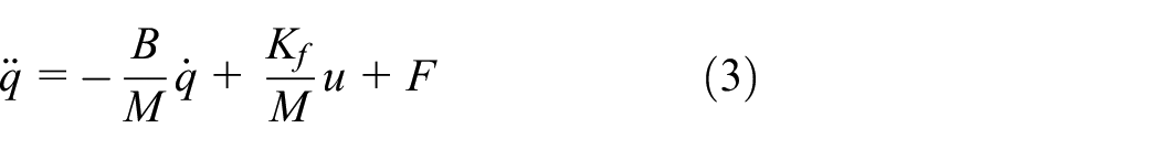
The mechanical motion equation of PMLSM is

where,
Selecting motor position

LuGre friction model
LuGre friction model can describe most of the static and dynamic characteristics observed in practice, and can accurately describe the friction phenomenon in multi-axis motion system. LuGre friction model uses the average offset of elastic bristles between two contact surfaces to characterize the dynamic behavior of friction. In practical application, the surfaces of two contact objects are uneven in micro state. LuGre friction model regards irregular surfaces as elastic bristles with random distribution. When the contact surfaces move relative to each other under the action of tangential force, the surface bristles will deform like springs. The average deformation of the contact surface bristles is related to the relative velocity. The higher the speed is, the greater the average deformation of the bristles is, and the friction force will also increase.
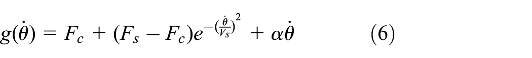
LuGre model is described as: 16

in which,

in which,
Contour error estimation
Any disturbance or parameter mismatch of each axis may affect the contour error. Taking the two-axis linkage system as the research object, the contour error estimation model 17 is shown in Figure 1.

Contour error estimation model.
where,
When the value of

Based on formula (7) and the definition of

From formulae (7) and (8), and according to the properties of vector and inner product, get


According to Figure 1,

The cross-coupled gains of the two axes are expressed as

Then, the contour error is estimated as:

Design of single-axis servo tracking control algorithm
PMLSM can generate electromagnetic thrust in the linear direction, which saves a lot of intermediate transmission links. However, in the actual operation, due to the absence of any buffering process, the control difficulty is increased when it is affected by nonlinear uncertainties such as load disturbance and friction.
The single-axis tracking control target is to effectively suppress the uncertainty of the system through the action of the controller when it is affected by the uncertainties such as friction, so that the position of the mover can track the desired trajectory. In order to improve single-axis motion accuracy, the block diagram of single-axis PMLSM servo control system proposed in this paper is shown in Figure 2. The control algorithm includes feedback linearization control, disturbance observer, and RBF neural network. The feedback linearization is used to track the position to ensure the stability of the system, the disturbance observer is used to observe and compensate the influence of friction, and the RBF neural network is used to compensate the observation error of the disturbance observer.

Block diagram of single-axis tracking control structure.
Feedback linearization control (FLC)
The purpose of feedback linearization is to transform the mathematical model of the nonlinear system into a simple linear model, and compensate the nonlinear part of it, so that the linear control method can be used conveniently. Compared with the approximate linearization, the feedback linearization is not limited to the vicinity of the equilibrium point and can be effectively controlled in a wide range. For the PMLSM servo system, the feedback linearization control method is used to linearize the system, and the drive system moves toward the direction of eliminating the error, so that the position of the mover can track the desired trajectory and ensure the global stability.
Define tracking error
It is assumed that the parameters of the servo system are known and the uncertainties such as friction can be measured, the feedback linearization control law is

in which,
By introducing equation (3) into equation (14), and obtain
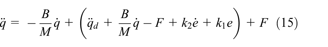
The following relation is derived

By selecting the appropriate controller gain

where,
Disturbance observer (DOB)
Feedback linearization design is based on ideal model control, which requires high accuracy of the controlled plant model. When the nonlinear system model has uncertain friction phenomenon, it is difficult to ensure the robustness of the system. Therefore, the disturbance observer is introduced to observe and compensate the friction, which is combined with the feedback linearization controller to eliminate the influence of friction on the system and improve the robustness.
Rewrite formula (3) as
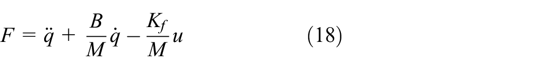
Disturbance observer is design as

In practical engineering, it is difficult to measure the acceleration signal
Define auxiliary vector

Substituting equation (19) into the derivative of equation (20), and get
To sum up, the nonlinear disturbance observer is designed as

Define observer error as

Since the friction model is constant or step change, it can be described by differential equation as

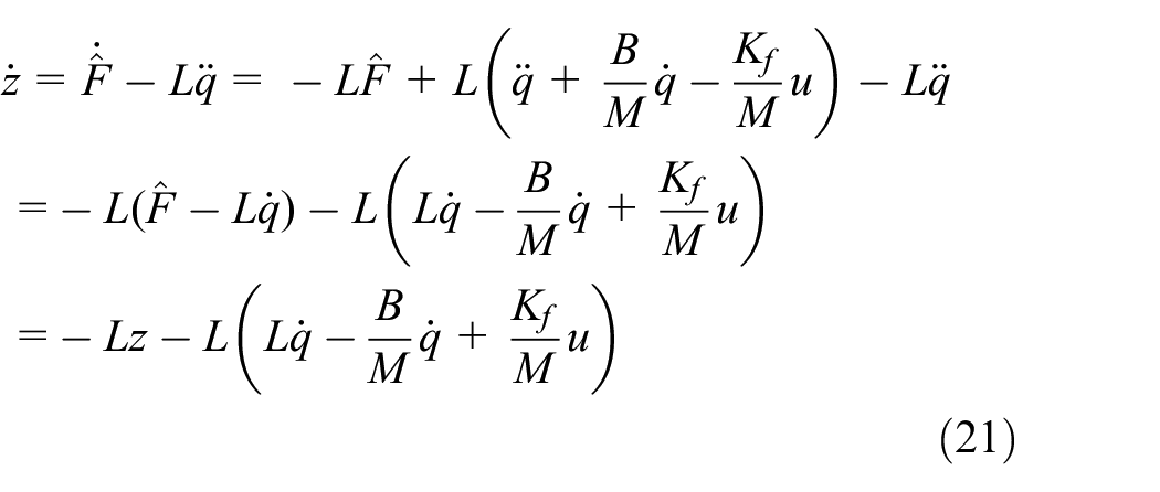
Substituting equation (21) into the above formula, and get
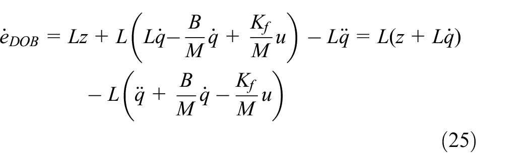
Substituting equations (18) and (22) into equation (25), then

Get

So, the observer is globally asymptotically stable.
RBF neural network
In the above control methods, the selection of

Get

Substituting the above equation into equation (17), the new control law is obtained as follows

RBF network has attracted much attention because of its good generalization ability, simple network structure, and avoiding unnecessary and lengthy computation. RBF neural network can approach any nonlinear function with a compact set and arbitrary precision. It has three layers: input layer, hidden layer, and output layer. The structure of RBF network is shown in Figure 3 in which,

in which,

Structure of RBF neural network.
The weight of RBF network is

Then the output of RBF neural network is

Two-axis cross coupled control
For the multi-axis motion control system, in addition to ensuring the tracking accuracy of the single-axis, the contour accuracy of the coupling of the two axes should be considered. Next, we use the cross coupled controller proposed by Koren and Lo 18 for contour control, so as to improve the contour accuracy. The structure of the cross-coupled control is shown in Figure 4.

Structure of cross-coupled controller.
in which,
In this section, PID controller is used as cross coupled controller. PID control has the advantages of small amount of calculation and good real-time performance. Through the action of PID cross coupled controller, the control precision of two axis contour is effectively improved.
The PID cross-coupled controller output is:

Simulation and analysis
The two-axis motion platform driven by PMLSM with friction is used as the control object to verify the effectiveness of the proposed control method. Motor simulation parameters are shown in Table 1.
PMLSM model parameters.

Feedback linearization control, disturbance observer, and RBF neural network is used for single-axis trajectory tracking control, and PID cross coupled controller is used to coordinate motion control between the axes. In which, position error
Controller simulation parameters are shown in Table 2.
Controller parameters.

A Heart-shape curve is selected as reference contour for simulation, which expressed as follows:

The effect of single-axis trajectory tracking and friction compensation are shown in Figure 5
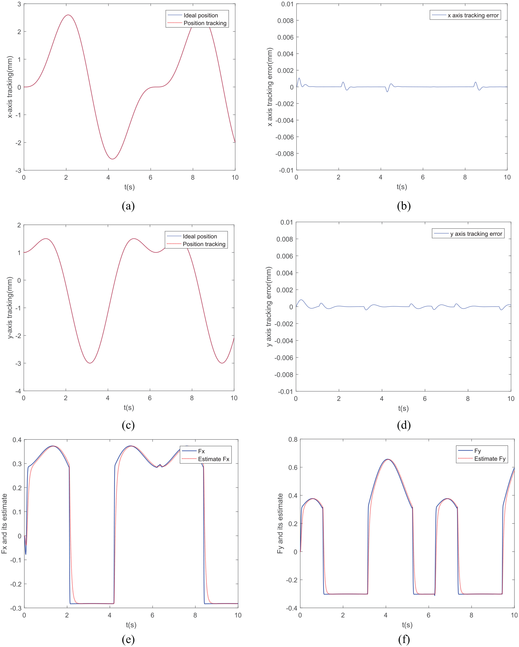
Simulation effect of single-axis trajectory tracking and friction compensation: (a)
Figure 5(a) to (d) show the position tracking and tracking error of the two axes respectively. Figure 5(e) and (f) show the LuGre friction and its observation of two axis. The simulation results show that the
For disturbance observer, it is difficult to select the observation gain. Usually a larger observation gain is selected to improve the observation accuracy, but it is easy to cause system instability. Taking

Influence of observation gain variation on friction compensation.
Beside, RBF neural network is introduced to approximate the disturbance observation error, which can further improve control performance. The approximation effect of RBF neural network is shown in Figure 7.
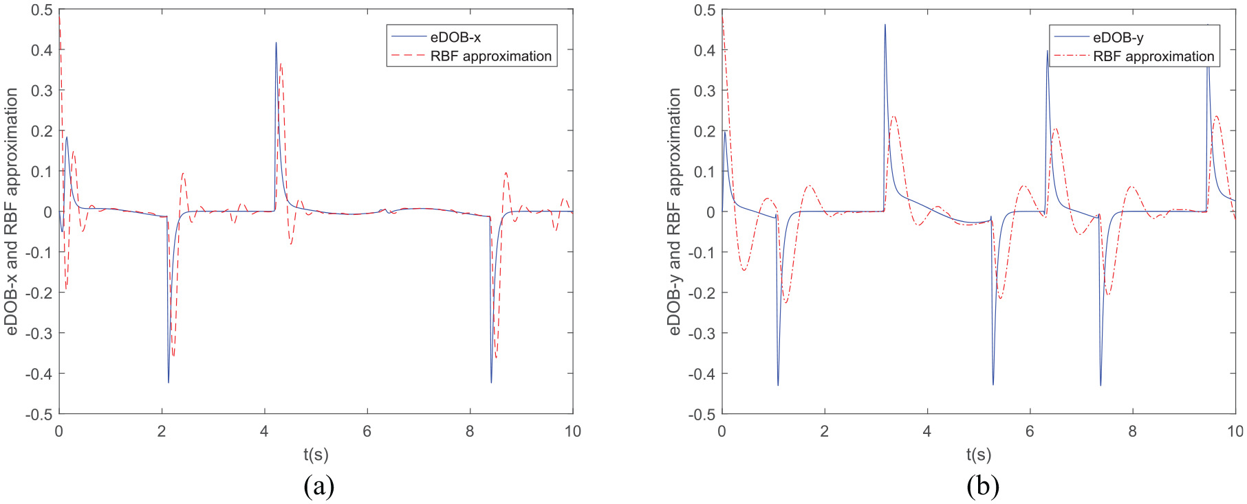
Two axis disturbance observation error and its RBF approximation: (a)
On the basis of ensuring the single-axis tracking performance, PID cross coupled control (
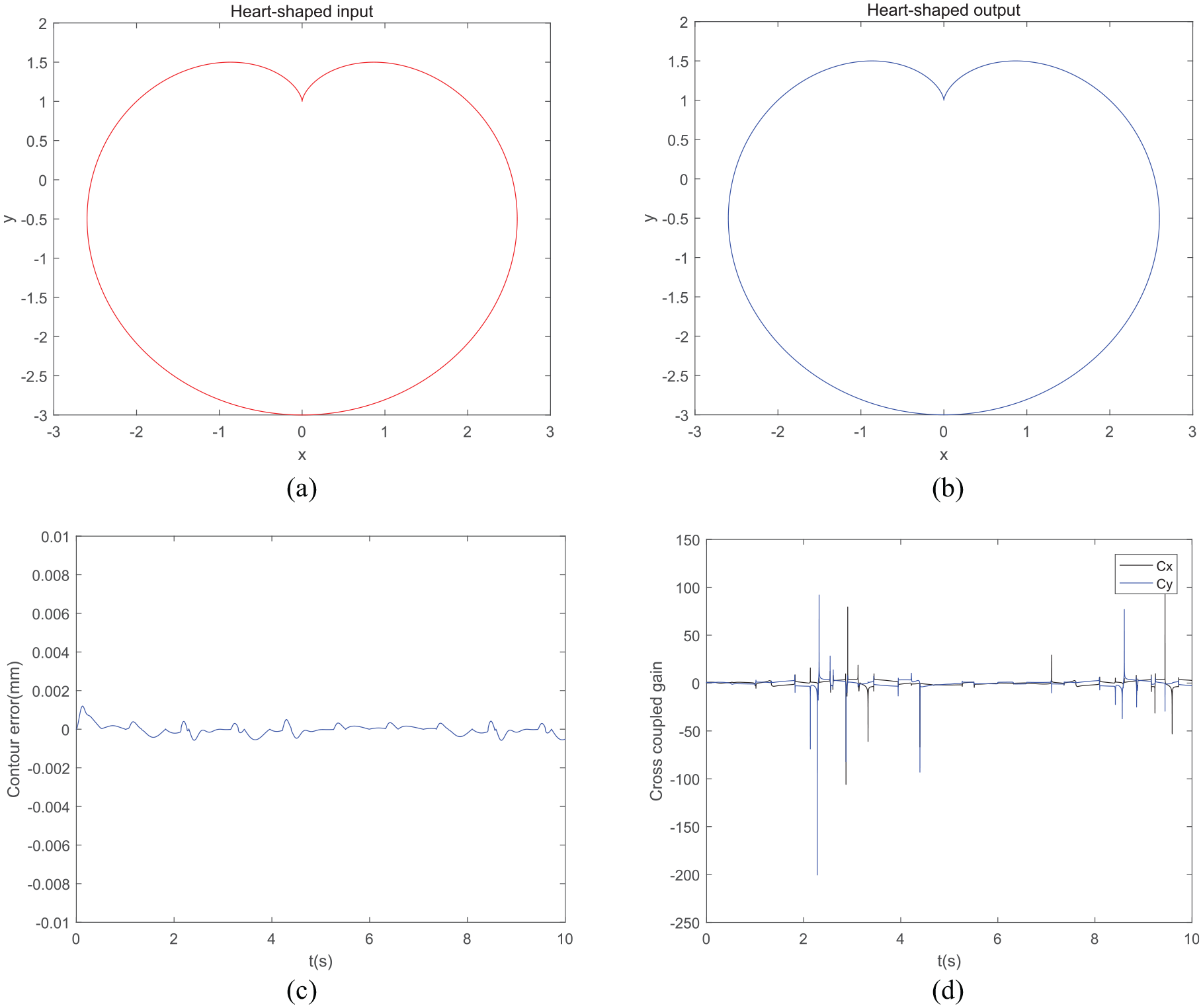
Simulation effect of contour control: (a) heart-shaped input, (b) heart-shaped output, (c) contour error, and (d) cross coupled gain.
Figure 8(a) and (b) are heart-shaped input and output, Figure 8(c) is the contour error. Figure 8(d) shows the real-time change of cross coupled gain. The simulation results of contour tracking show that the output can track the reference input contour very well, the contour error is close to zero, and the system has very high contour tracking accuracy.
In order to better verify the effectiveness of the proposed control algorithm, the proposed control algorithm (FLC + RBFDOB) is compared with the feedback linearization (FLC), feedback linearization, and disturbance observer (FLC + DOB) respectively. The comparison results are shown in Figure 9.

Comparison results under the action of three control algorithms: (a)
Among them, Figure 9(a) and (b) respectively show the
The maximum value, average value of tracking error, and contour error under the action of the three control methods are shown in Table 3
Error comparison table.

Conclusions
For two axis permanent magnet linear servo motor contour motion control system, it is easy to be affected by friction disturbance, which reduces the single-axis tracking accuracy, a friction compensation control algorithm is proposed. The control algorithm consists of feedback linearization controller, disturbance observer, and RBF neural network. The feedback linearization is used for position tracking control, the disturbance observer is used to observe and compensate the friction, and the RBF neural network is used to approximate the disturbance observation error to further improve the tracking accuracy and robustness of the system. Then, in order to solve the problem of contour error caused by different parameters and dynamic mismatching between two axes, PID cross coupled control is used to coordinate control between axes, so as to improve the contour control accuracy.
Comparing the proposed control algorithm FLC + RBFDOB with the single FLC and FLC + DOB, it is found that the tracking error and contour error are very obvious under the action of FLC alone. After adding disturbance observer, the tracking error and contour error performance are significantly improved. It can be seen from error comparison Table 3 that the average tracking error of the
Footnotes
Handling Editor: James Baldwin
Declaration of conflicting interests
The author(s) declared no potential conflicts of interest with respect to the research, authorship, and/or publication of this article.
Funding
The author(s) disclosed receipt of the following financial support for the research, authorship, and/or publication of this article: This research was supported by Joint Fund of Zhejiang Provincial Natural Science Foundation, Grant No. LTY20E050001.
Data availability
The data used to support the findings of this study are included within the article.