
Abstract
In machining, tool/workpiece interface parameters are complicated to estimate by experimental means alone. Numerical methods can then give critical solutions to predict and analyze the parameters influencing the machining. The friction between the tool and the cutter has a direct influence on the milling parameters. Therefore, it is necessary to understand the friction mechanism between the tool and the workpiece to estimate the milling parameters of Nomex honeycomb structures correctly. This work aims to present a 3D Finite Element numerical model allowing the prediction of the cutting forces correctly, the morphology of the chips, and the surface quality generated during the milling of this type of structure. These studies were obtained using the commercial software ABAQUS/Explicit. It has been demonstrated that the coupling between the isotropic elastoplastic approach and the Coulomb friction law can easily simulate the milling of Nomex honeycomb structures and gives excellent results in comparison with those obtained experimentally.
Introduction
The sandwich structures of the honeycomb core occupy a significant place in the construction of composite parts. The alveolar core of this type of structure represents a technical and scientific challenge during machining. One of the most used materials for the manufacture of honeycomb core is Nomex. This non-metallic and ultra-light material is made of aramid fibers. It offers very high mechanical properties in terms of its light weight and strong resistance. 1 However, the machining of these kinds of structures is a technical challenge for manufacturers. This depends on the composition of the Nomex walls defined by aramid fibers and phenolic resin. To overcome these challenges, physical-chemical techniques have been proposed to solidify the structure and avoid the cells’ vibration.2,3 Depending on the geometry of the desired part, there are different types of machining operations. The most important and most used in the industrials sectors are turning, drilling, and milling. The removal of material is done by the tool’s mechanical action, which generates the formation of one or more chips. The use of lubricants is often necessary to reduce the temperature rise generated by the friction of the chips on the cutting face of the tool and by the plastic deformation of the machined material. Several suppliers offer different tools which are characterized by an almost unique geometry and design. This variety of tools is due to the different types of machining, the different materials used to perform the machining, the complex configurations and the type of lubrication chosen.4,5 Material removal machining is a widespread technique that finds applications in the automotive, naval, railway, and aeronautical industries. Our studies focus in particular on the milling Nomex honeycomb structures. In the current context of the search for high quality levels of manufactured products, the possibility of obtaining realistic predictions of cutting force values becomes very important. In fact, knowing the level of cutting forces during a machining operation makes it possible to reduce the number of long and expensive tests, the goal of which is to determine the best cutting conditions and the best tool geometry for an operation machining given. Several researches work on cutting phenomena can be cited. Aydın and Köklü6,7 have been analyzed the prediction of milling forces and segmented chip morphologies. They found that mesh density has a direct influence on milling forces and chip segmentation. To understand the machinability of these structures, experimental tests were carried out, taking into account the complex geometry of honeycombs and the cutting tool.8–10 As the machined surface integrity is strongly related to the manufacturing process, it becomes necessary to optimize the machining parameters to improve the surface quality. Several authors have examined the cutting conditions on the surface quality as well as the cutting forces during milling of Nomex honeycomb structures.11–13 For this purpose and compared with the classical experimental methods, the numerical modeling of the machining becomes an economic and technical tool more and more unavoidable. Although it is one of the oldest manufacturing processes, machining is still subject to reliable predictive modeling. The multi-physics aspect of cutting, which is governed by several coupled phenomena such as thermal, mechanical, and physicochemical effects, 14 makes the modeling of cutting complex. One of the most widely used numerical modeling methods is the finite element method. It is well known that the Nomex material is fabricated from aramid phenolic resins and fibers. According to the literature, several authors have modeled the Nomex material as orthotropic or isotropic.15,16 However, the orthotropic approach has different mechanical properties. Therefore, he should define local landmarks for each direction of the hexagonal cells of the Nomex honeycomb. On the contrary, the elastoplastic approach does not take into account the direction of the Nomex paper. Thus, this study focused on the isotropic elastoplastic method that was found to be simple in accordance to calculation time. This paper developed a three-dimensional numerical model for milling Nomex honeycomb structures based on the finite element method using ABAQUS/Explicit software. To easily simulate the milling of Nomex honeycomb structures. Initially, we chose the coupling between the isotropic elastoplastic approach and the Coulomb friction model in order to calibrate the friction coefficient through experimental studies in terms of cutting forces. The latter was applied without using a material separation criterion, which makes our model faithful to the physics of cutting. Secondly, a parametric study was performed to verify the effect of the depth of cut on the morphology of the chips, the tilt angle on the cutting forces and finally, the quality of the machined surface.
Materials and tools studied
To properly analyze the milling of Nomex honeycomb structures, the studied structure has 86 cells. The dimensions of the honeycomb structure are presented in Figure 1. Table 1 represents the Nomex honeycomb structure mechanical properties.

Nomex honeycomb core.
Geometrical characteristics of honeycomb core.

The milling of composite honeycomb structures requires special tools with a specific geometry. In this study, a combination tool was used. It is composed of two parts: a lower part consisting of a conical tungsten carbide disc with smooth edges with 18.3 in diameter and having a rake angle of 22° and a flank angle of 2.5°. An upper part consisting of a cylindrical body made of high-speed steel with 16 mm in diameter with ten helices containing chip breakers (Figure 2(a)). A screw mechanically connects these two parts. The geometrical dimensions of the tool are shown in Figure 2(b).

The CZ10 tool used for milling the Nomex honeycomb core.
Modeling of the cutting process
In this paper, a 3D milling model of Nomex honeycomb structures is implemented using the FE code Abaqus/Explicit in version 6.17. The Lagrangian formulation is defined in dynamics with the consideration of the tool-workpiece interactions. Like the experimental study, the cutting conditions are applied to the cutting tool reference point while the workpiece is assumed fixed. The tool is modeled as rigid, while the part is modeled as deformable. The feed rate f and the rotation speed N were applied at the reference point where the cutting forces are determined (Figure 3).

Milling conditions applied to the RP reference point of the cutting tool: N is the rotation speed and f is the feed rate.
To ensure full contact between the tool and the honeycomb structure at the start of the simulation an initial engagement is designed taking into account the specific geometry of the cutter and the smooth knife thus reducing CPU time (Figure 4).
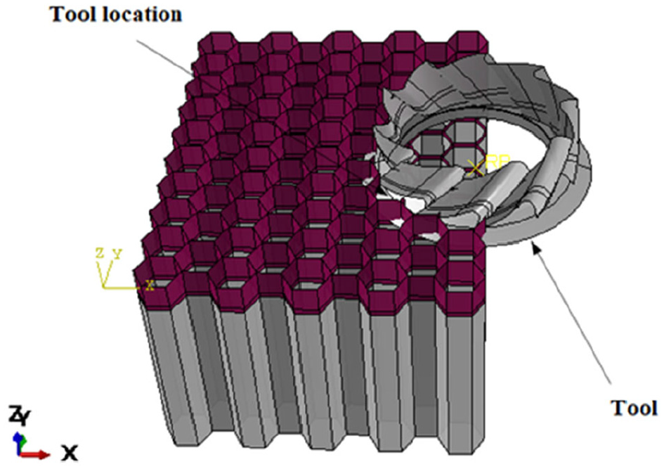
Initial tool engagement in honeycomb workpiece.
Workmaterial behavior
The use of an adequate and representative behavioral law remains essential to simulate the process of chip formation in machining effectively. To properly represent the behavior of machined materials, various phenomena related to the cutting process must be taken into account. Indeed, the accuracy of the results obtained numerically depends essentially on the choice of the type of behavior law of the structure’s material. The behavior law must consider these main phenomena to reproduce the cutting process as well as possible. To simulate the right results in terms of cutting forces, chip morphology, and machined surface quality, it is essential to consider the right compromise between calculation time and accuracy of results. In this respect, we used the isotropic elastoplastic approach. The latter is known for its simplicity of implementation.17,18 The mechanical properties attributed to the Nomex paper are presented in Table 2. The continuous and incremental feed of the tool generates an increasing multiaxial change in the material. Initial stress analysis is used to verify the criteria and their associated failure modes. When a failure mode has detected the value 0.1208, this automatically causes the material to break and the chips to form.

The isotropic elastoplastic behavior of a material is the sum of elastic deformation and plastic deformation:

ε is the tensor of the total stresses. εel and εp are respectively the elastic and plastic strain tensors.
The elastic part is subject to Hooke’s law, given by the following formula:

C is the tensor of the reasoner of order 4.
Therefore, the law becomes:

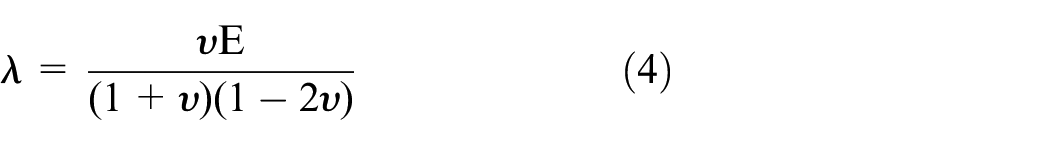
For a complete definition of the elastic behavior of the material, it is essential to determine the coefficients of Blade λ and µ. The equations relating the coefficients λ and µ, the Young’s modulus E and the Poisson’s ratio ν by are as follows:

Tool–Workmaterial interface behavior (interface friction law)
Friction at the tool/workpiece interface is difficult to determine because it depends on the local sliding speed, contact pressure, temperature, and material behavior of the tool and the workpiece. In machining, friction influences the cutting forces, chip morphology, and machined surface quality. Therefore, it is necessary to understand the friction mechanism between the tool and the chip to estimate the parameters influencing the machining correctly. In the literature, several friction laws allow the modeling of contact problems in machining. These laws allow the determination of the tangential component of the stress vector at the tool-chip interface. The simplest friction model is the Coulomb model. Generally, the friction coefficient f is assumed to be constant for a given contact interface. In this study, the friction at the tool-workpiece interface is modeled by the modified Coulomb’s law of friction. This is defined by the relationship between the normal frictional stress σn and the shear frictional stress τf as follows:
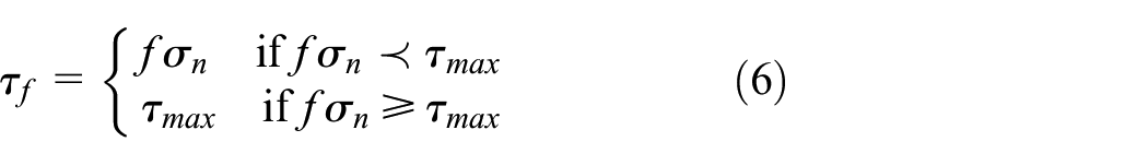
Where f is the friction coefficient, σn is normal stress, and τmax is the shear stress limit considered equal to the initial plastic flow shear stress σ0/√3, with σ0 is the initial yield stress of the Workmaterial.
To correctly predict the milling process, it is necessary to follow the cutting forces

Mesh and boundary conditions
The 3D FE analysis of the chip formation process for milling Nomex honeycomb structures highlights the effect of mesh density on the cutting operation. The adjustment of these numerical parameters is essential to obtain reliable results. A solution, which seems to be efficient at first sight, allows searching for the right compromise between the computation time and the reliability of the results. In this sense, the studied part is meshed by 4-node S4R shell elements with reduced integration with hourglass-control and element deletion. Simultaneously, the cutting tool is meshed by rigid quadrangular elements of type R3D4 (Figure 5). The recommended mesh size for this study is 0.5 mm. This value is chosen after mesh convergence tests. A compromise between result accuracy and reasonable CPU time has been taken into consideration.

Mesh used in the EF model.
To bring closer to the experimental studies, we chose the following boundary conditions (see Figure 6):

Boundary conditions used in the EF model according to the experimental setup carried out. 20
Results and discussion
Effect of friction coefficient on cutting forces
The friction coefficient f is a physical parameter essential for an optimal definition of the contact at the tool/workpiece interface. This parameter is difficult to measure experimentally and is a significant lock for an optimal milling model. We, therefore, propose to study the influence of this parameter numerically on the cutting forces. The idea is to take four values of the friction coefficient [0.1; 0.2; 0.25; 0.29]. and to carry out the cutting simulation for each value in order to be able to study its influence on the results and thus to calibrate it compared to the experimental results and to those under the same cutting conditions f = 3000 mm/min, N = 23,000 rpm. 20 The numerical simulations were performed for 0.04 s, which represents a tool path of about 2 mm. Figures 7 and 8 shows the evolution of the cutting force and its components as a function of rotation speed for different values of friction coefficient.

Evolutions of components, Fx and Fy for f = 3000 mm/min, N = 23,000 rpm, depth of cut ap = 2 mm.

Evolutions of components, FAvg and Fz for f = 3000 mm/min, N = 23,000 rpm, depth of cut ap = 2 mm.
According to the results presented in Figures 7 and 8, it can be seen that the cutting forces are relatively sensitive to the friction coefficient f. These have been the subject of recent research work,21,22 and which have shown that they have a significant influence on the cutting force. Secondly, we compared the numerical results obtained and the experimental results measured, and under the same machining conditions mentioned previously. 20 We find that the numerical results are very close to the experimental results for the value of friction coefficient f = 0.1. Therefore, the coefficient of friction retained for our study is f = 0.1. This value is currently the best value of the friction coefficient concerning the cutting force. Therefore, we can conclude that this value presents the right compromise between the proposed law of behavior (isotropic elastoplastic approach) and the law of friction of the coulomb (coefficient of friction) to approach a complete parametric study. The evolution of the cutting forces as a function of the rotation speed is compatible with that known for composite materials where the decrease of the forces with the increase of rotation speed is observed. In this respect, we noticed that the Fz component is larger than the Fx and Fy components. The latter represents well the out-of-plane behavior of the Nomex honeycomb structure. The Fy component is not compatible with the experimental results because of removing damaged elements and the loss of contact with the tool.
Effect of the tilt angle on the cutting forces
The previous study made it possible to calibrate the coefficient of friction through experimental studies. In this section, a parametric study is then conducted to analyze the interactions between the milling parameters and confirm the effect of these parameters. To study the influence of the tilt angle on the milling forces, numerical simulations were conducted by varying this angle. Four tilt angles were examined, α = 0°, α = 5°, α = 10°, and α = 15° (see Figure 9). The recommended cutting conditions for this study are f = 3000 mm/min, N = 23,000 rpm. The numerical simulations were performed for 0.04 s, which represents a tool path of about 2 mm. The obtained results have been plotted in Figures 10 and 11.
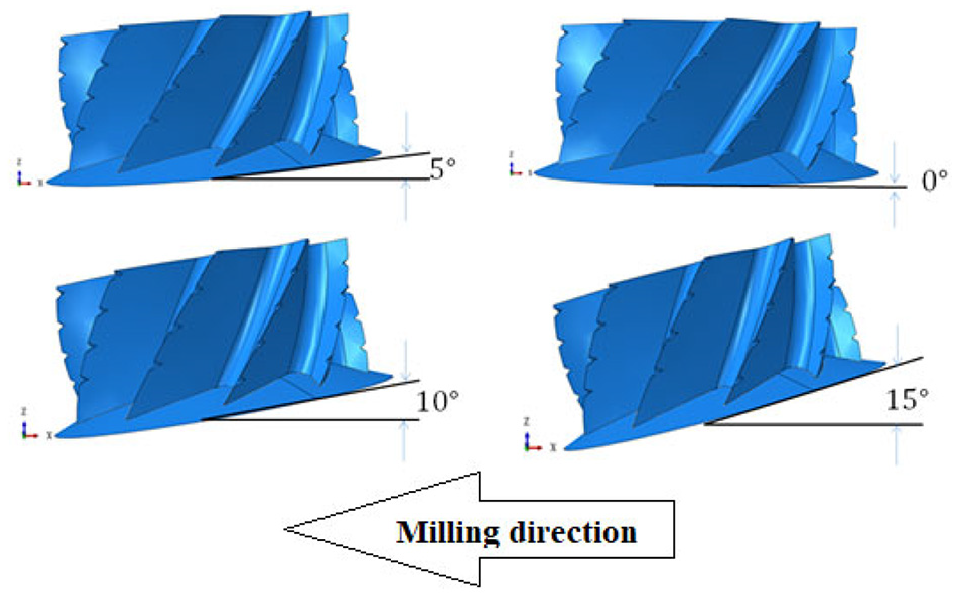
The tilt angle of the cutting tool.
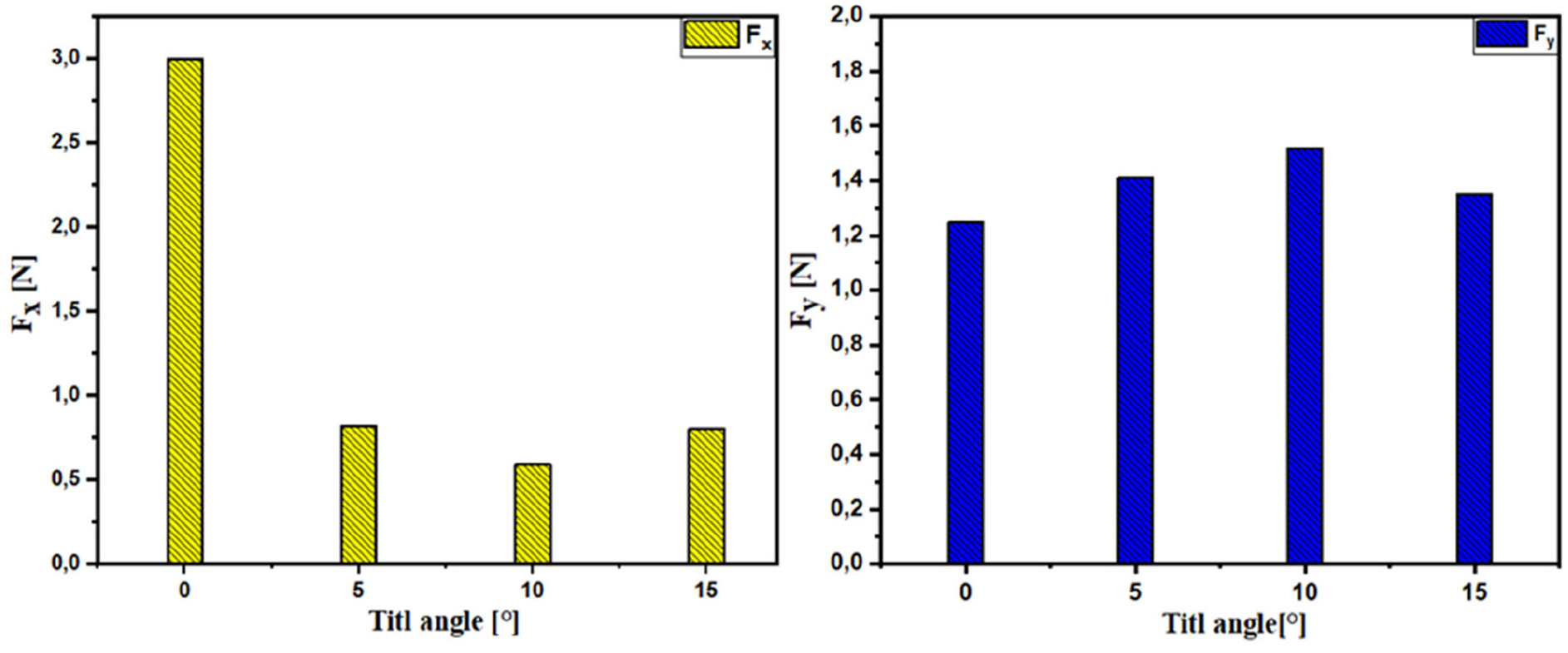
Evolutions of components, Fx and Fy for f = 3000 mm/min, N = 23,000 rpm, depth of cut ap = 2 mm.

Evolutions of components, Fz and FAvg for f = 3000 mm/min, N = 23,000 rpm, depth of cut ap = 2 mm.
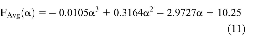
The effect of the tilt angle on the cutting force FAvg and its components when milling Nomex honeycomb structures is observed in Figures 10 and 11. A slight variation in cutting forces was found with increasing tilt angle between α = 5° and α = 15°. This trend is also observed for the Fx and Fy components. It is also important to note that the tilt angle has a significant influence on the Fz component such that the values of the vertical Fz component decrease with increasing tilt angle. This is because the surface of the smooth knife contacts the surface of the Nomex honeycomb structure. With the increase of the tilt angle, the contact between the lower surface of the tool and the workpiece decreases, so the Fz component decreases. In the end, the cutting tool with large angles generates cutting forces lower than those found with the cut for an angle of α = 0°, which allows having lower wear of the tools than with tools with a cutting angle of α = 0°. Jaafar 23 made the same conclusion in his experimental studies. In parallel, approximate correlations in the form of third-order polynomials can be proposed between cutting forces and tilt angles when milling Nomex honeycomb structures and those under the same machining conditions mentioned above.


Effect of cutting depth on cut morphology
It is well known that the rotation and feed rates have a direct influence on the cutting forces, the machined surface quality, and the formation of the generated chips.3,24,25 In this section, we are interested in studying the influence of the depth of cut on the chip morphology. In this respect, two cutting depths have been examined 2 and 12 mm. To highlight this point, numerical simulations have been carried out with rotation speeds N = 23,000 rpm and a feed rate f = 3000 mm/min. The numerical simulations were performed for 0.04 s, which represents a tool path of about 2 mm. Figures 12 and 13 shows the morphology of the chips in front of the tool for the two depths tested.

Effect of the cutting depth on the morphology of the chips: f = 3000 mm/min, 23,000 rpm, ap = 2 mm.
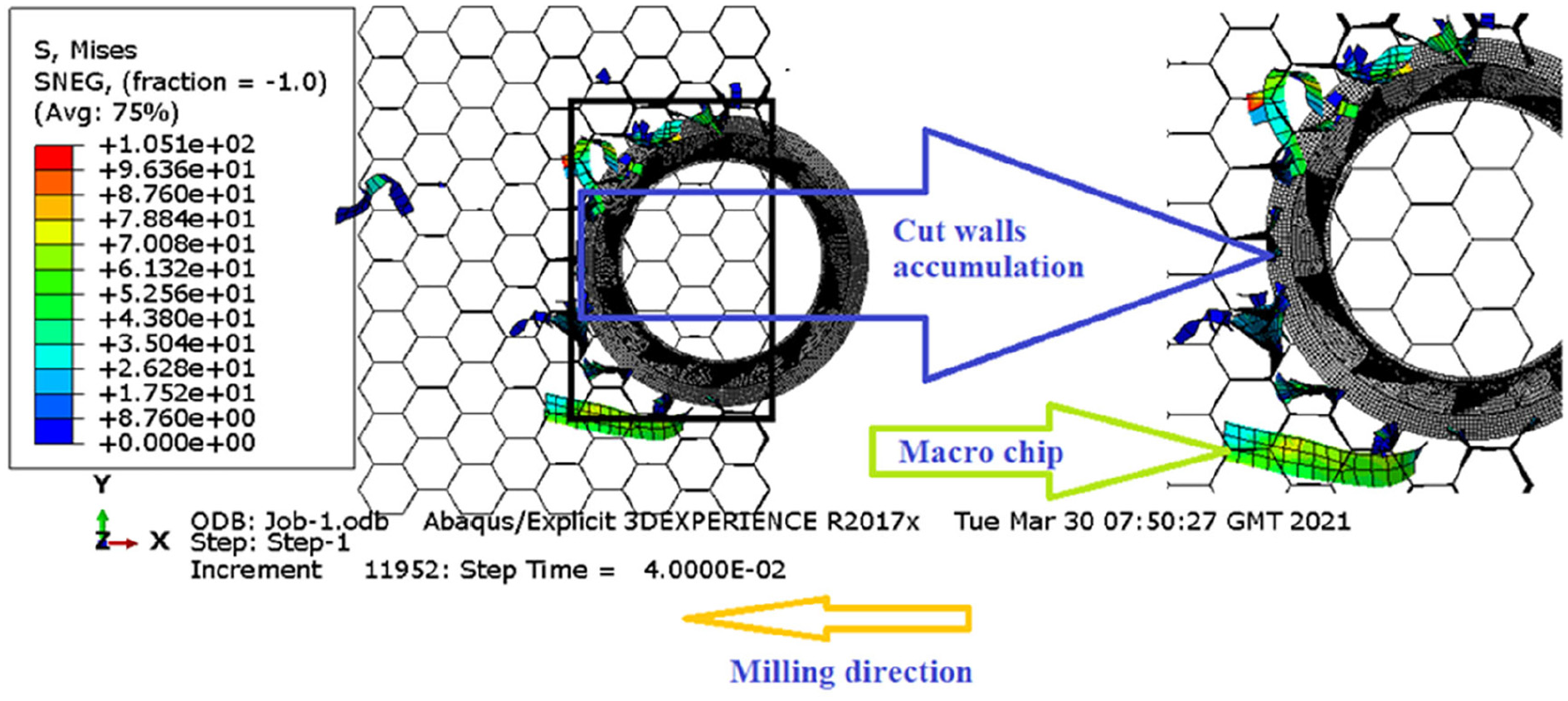
Effect of the cutting depth on the morphology of the chips: f = 3000 mm/min, N = 23,000 rpm, ap = 12 mm.
The circular knife chips the walls. The contact between the tool’s knife and the honeycomb walls is permanent, with the feed and rotation of the tool. The walls are cut by an impact process between the smooth knife and the thin walls of the Nomex honeycomb. Once the element stressed by the smooth knife reaches its limit stress, it will be removed in order to free the passage to the tool. They knew that the size and morphology of the chips depend on the machining conditions.11,20 The lower the rotation speed and the higher the feed rate, the larger the chip size. As the tool advances, the cut walls rub on the upper surface of the chip until they reach the shredder. This phase favors the accumulation of the walls in front of the upper part of the tool, pushing them back and generating the chip. The accumulation of material in front of the tool causes an increase in cutting, thus influencing the morphology of the chips. Numerical simulations show two different chip morphologies when milling Nomex honeycomb structures (Figures 12 and 13). We found that the size of the chip is strongly dependent on the depth of cut so the chip size increases with increasing depth of cut. This is explained by the rate of material machined. In general, macro chips are not desirable in industrial applications. This is due to the problems generated, which considerably affect the machining conditions: damage to the cutting edge, forming a heap of material on the cutting area. Finally, under the same machining conditions, it is observed that milling at 2 mm depth forms segmented chips easier than 12 mm. This segmentation allows machinability in terms of low machining forces. Finally, the recommended depth for machining Nomex honeycomb structures is 2 mm.
Effect of cutting depth on the surface quality
The surface quality of Nomex honeycomb structures is of paramount importance for their use in sandwich structures. The machined surface is in direct contact with the sandwich skins. Poor bonding of the sandwich material affects its peel strength, and a strip makes the bond of adhesive connecting the machined surface of the honeycomb to the skin. Poor machining of Nomex honeycomb materials is characterized by the appearance of tearing at the cells and uncut aramid fibers.27–29 These defects constitute the set of shape defects. 30 The determination of this defect is of paramount importance to validate the use of this type of structure as the high-performance core for sandwich materials. This defect has a direct influence on the maintenance of the sandwich material assembly. Its occurrence causes anomalies in forming the adhesive menisci on both sides of the honeycomb walls.28,29,31 Knowing that the feed rate and rotation speed directly influences surface quality. The surface quality of the Nomex honeycomb structure, improves with low rotation speeds and high feed rates. 23 In this section, we have studied the influence of the depth of cut on the machined surface quality. Two depths of cut were studied 2 and 12 mm. The cutting conditions examined for this simulation are f = 3000 mm/min, N = 23,000 rpm. Figures 14 and 15 shows that the depth of cut has no significant influence on the quality of the machined surface. Jaafar 23 made the same conclusion during his experimental studies.
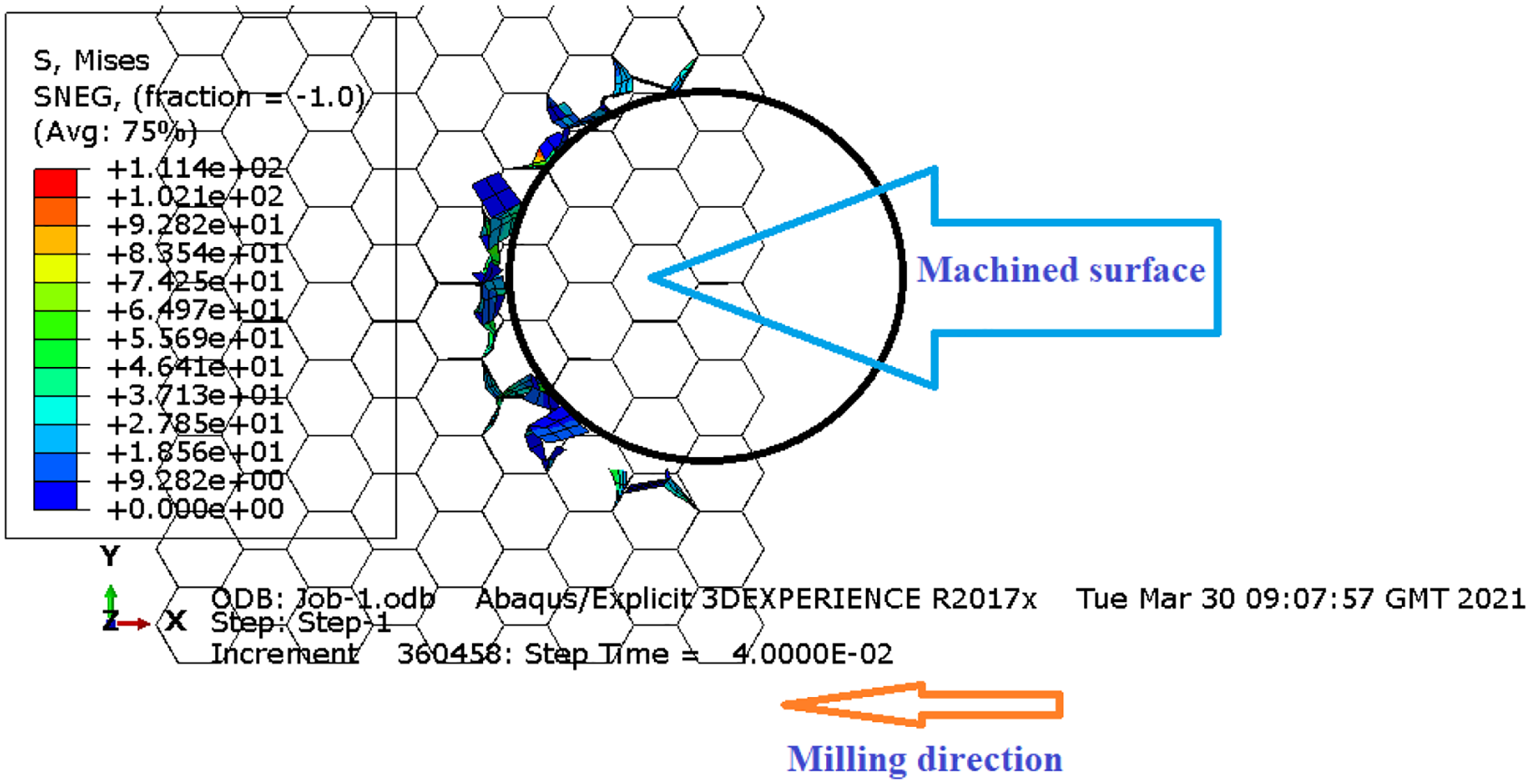
Honeycomb milling surfaces: f = 3000 mm/min, N = 23,000 rpm, ap = 2 mm.

Honeycomb milling surfaces: f = 3000 mm/min, N = 23,000 rpm, ap = 12 mm.
Conclusion
To analyze the cutting process in milling operation of Nomex honeycomb structures, including evaluating cutting forces, chip morphology, and generated surface quality. A 3D FE model is developed using the commercial software ABAQUS/Explicit. The FE model was calibrated after studying the influence of the friction coefficient on the cutting forces. It was found that the friction coefficient has an effect on the cutting forces well as on the chip morphology. A compromise between the simulation results and the experimental results from the literature was established. Moreover, this corresponds to a judicious choice of the isotropic elastoplastic approach and the value of the friction coefficient and a good calibration of the model. After implementing the 3D FE model of milling of Nomex honeycomb structures and its calibration, we approached a parametric study concerning the influence of the tilt angle on the cutting forces. The obtained results allow us to conclude that the tilt angle between 5° and 15° has no effect on the cutting forces and its components except the Fz component of the cutting force decrease with the increase of the tilt angle. This is explained by the slight contact between the surface of the knife and the surface of the honeycomb structure. On the other hand, we checked the influence of the cutting depth on the morphology of the chips. The obtained results allow us to conclude that the depth of cut directly influences the morphology of the chips so that the great depths generate macro-cuts and vice versa. Also, we found that the depth of cut does not influence the surface quality generated. Finally, the coupling between the isotropic elastoplastic approach and the Coulomb friction law can correctly simulate the milling of Nomex honeycomb structures.
Footnotes
Handling Editor: James Baldwin
Declaration of conflicting interests
The author(s) declared no potential conflicts of interest with respect to the research, authorship, and/or publication of this article.
Funding
The author(s) received no financial support for the research, authorship, and/or publication of this article.