
Abstract
In order to improve the steering flexibility of agricultural machinery in hilly and mountainous areas, a multi-mode steering system with front wheel steering, rear wheel steering, and four-wheel steering has been developed. The hydraulic steering system based on load sensitivity principle and proportion-integration-differentiation (PID) controlling algorithm was designed, which overcomes the negative impact of external load changes on flow control accuracy. The mechanical-hydraulic-controlling coupling model established in the AMESim and the sequential quadratic combinatorial optimization algorithm (SQCOA) was adopted to obtain the optimal combination of PID parameters. The simulation results demonstrate that the parameters such as pressure, speed, displacement of hydraulic cylinders, etc. in different steering modes meet the design requirements. To examine and verify the system performance, the test platform was researched and developed for conducting steering radius and displacement measurement. The experimental data illustrated that the front and rear hydraulic cylinders have good synchronization accuracy in four-wheel steering mode, and the fast switch of steering mode can be realized. The maximum error rate of is steering radius 4.21% and 3.77%, respectively, in two-wheel steering and four-wheel steering modes. The research methods and conclusions can provide a theoretical basis and reference for the other steering system development.
Keywords
Introduction
Due to its large population and land scarcity, the amount of arable land on a per capita basis in China is only half the global average, and most of the cultivated land is distributed in hilly mountain areas. The farmland area in the hilly mountains is small, irregular and has poor road conditions.1,2 In Chongqing, for example, the arable land area in 2019 was 2.45 million hectares, accounting for 98% of the total in hilly mountains. 3 On the other hand, the front wheel steering or four-wheel steering are adopted by existing agricultural machinery, and there is no multi-mode steering system.4,5 This leads to a lot of inadaptability of agricultural machinery in hilly and mountainous areas. The problem of weak steering flexibility and poor maneuverability is particularly prominent.
The steering system for agricultural machinery is divided into mechanical steering system, hydraulic power steering system, wire-controlled steering system, etc.6–8 Hydraulic steering system is mainly composed of hydraulic pump, steering gear, steering cylinder, with the advantages of small size, flexible and lightweight, stable performance. It is very suitable for agricultural machinery with low walking speed and large steering resistance.9,10
Recently, a considerable literature has grown up around the theme of hydraulic steering system for agricultural machinery. One of the most cited studies is that of Jeyed and Ghaffari 11 who developed a new kind of four-wheel steering system for hilly mountain tractors. The movement state of the steering cylinder at different speed signals and the steering angles are calculated based on Adams dynamics analysis. To further examine the dynamic performance of four-wheel steering system, Xia and Luo 12 studied the four-wheel steering system of self-propelled sprayer. The anti-slip steering system of self-propelled sprayer was analyzed by Mao et al. The controlling accuracy of the anti-slip steering system at different steering angles was tested. The results show that the largest and average error rates are 2.01% and 1.25%, respectively. 13 However, most studies in the field of steering system have only focused on four-wheel steering, and the multi-mode steering system has not been dealt with. Four-wheel steering mode effectively reduces the turning radius and improves steering flexibility in small fields. At the same time, it can also achieve the same steering trajectory of front and rear wheels. So crop crushing damage during steering process can be reduced. Two-wheel steering has less steering resistance force, but the steering trajectory of front wheel and rear wheel is different due to its different steering center. The driver can choose the steering mode according to the actual conditions. In this way, the steering flexibility will be enhanced compared to the single steering mode.
Li et al. developed a multi-wheel steering system for self-walking sprayers. The mathematical model of the steering system is simulated by Matlab/Simulink and the multi-wheel steering system has a maximum follow-up error of 2.82°. 14 However, there have been no attempts to examine the operating pressure, speed, and other parameters in the steering process in his study. One longitudinal study by Geng et al. 15 found that the road surface unevenness will give random excitation to the tires, which will affect the steering dynamics performance. Bobin et al. 16 designed a priority valve for hydraulic steering systems. Taking the minimum flow overshoot as the design goal and the spool diameter, spring stiffness, and throttle orifice area as design variables, the robust design based on the loss model is completed. However, the study did not take into account the entire hydraulic steering system. In a comprehensive study of crawler vehicle, Liu et al. 17 established the steering system model of the crawler vehicle by using co-simulation of RecurDyn and AMESim software. The hydraulic system parameters were analyzed when the crawler car was steered in place. There has been no detailed investigation of the hydraulic steering system of wheeled vehicles in his study. In this paper, the designed new multi-mode steering system adopted load sensitive hydraulic system which will improve the control precision by pressure feedback mechanism. It effectively suppresses the influence of load pressure fluctuation on the speed of actuator.
In order to improve the steering flexibility of agricultural machinery in hilly mountain areas, a novel multi-mode steering system which can improve steering flexibility and terrain adaptability with front wheel steering, rear wheel steering, and four-wheel steering has been developed. The mechanical-hydraulic-control coupling model of multi-mode steering system is established in AMESim, and the optimal combination of PID parameters is obtained by using SQCOA. The test platform of the multi-mode hydraulic steering system is researched and developed to verify its performance. The designed hydraulic steering system can be extended to other vehicles. The whole flow chart is displayed in Figure 1.

The whole flow chart.
Materials and methods
Steering dynamic theory
When the steering torque is greater than the steering resistance moment, the vehicle is able to steer under the operation of the steering mechanism. There are three steering modes for vehicles: the first is to change the steering angle of the wheel, the second is to change the driving force on both sides of the walking device, and the third is a combination of the above two ways. The first steering way is always adopted by wheeled vehicles. The basic steering requirement for wheeled vehicle is that each wheel must run in pure rolling state, which means that all the wheels must have the same instantaneously steering center. This condition is known as the Ackman steering the theology.
Analysis of two wheels steering system
The status of the front wheel steering vehicle and the rear wheel steering vehicle during left steering is shown in Figure 2(a) and (b), respectively, with point O (Figure 2) being the momentary steering center. 18

Two wheels steering system: (a) front wheel steering and (b) rear wheel steering.
The Ackermann conditions for front wheel steering and rear wheel steering vehicle can be represented by formulae 1 and 2.


Where
For two-wheel steering vehicles, the relationship curves between the outer wheel steering angle and the inner wheel steering angle under different front wheel pitch and wheelbase configurations are displayed in Figure 3. The difference between the inner and outer steering angles diminishes as the ratio of wheel pitch to wheelbase decreases.

The relationship curves between the outer wheel steering angle and the inner wheel steering angle for two-wheel steering vehicles.
Analysis of four wheels steering system
Four-wheel steering includes same-phase steering and out-phase steering. The same-phase steering is mainly used for high-speed vehicles to improve steering stability, and out-phase steering, which is used for low-speed vehicles to reduce steering radius.
Out-phase refers to the opposite steering direction of the front and rear wheels during steering. For agricultural machinery, the four-wheel steering system usually adopts a symmetrical out-phase steering method, that is the two inner wheel steering angles are the same size with opposite direction, and the two outer wheel steering angles are the same size with opposite direction.
This steering method allows the locus of front and rear wheels to be the same, reducing damage to the crops. The state of the out-phase four-wheel steering vehicle during the left steering is displayed in Figure 4. According to the relations, it can be deduced that the steering angle calculation formula of each wheel. 18


Four wheels steering system.
Where
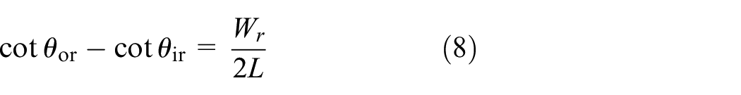
For the symmetrical out-phase steering mode, the relationship between the wheel steering angle on the inside and outside of the front wheel can be expressed by formula (7), and the relationship between the wheel steering angle on the inside and outside of the rear wheel can be expressed by formula (8).

The relationship curves between the outer wheel steering angle and the inner wheel steering angle under different wheel pitch and wheelbase configurations is shown in Figure 5. It illustrates that, similar to two-wheel steering, the difference between the inner and outer steering angles decreases as the ratio of wheel pitch to wheelbase decreases. However, as the ratio decreases, the difference between the inner and outer steering angle decreases slowly compared to the two-wheel steering mode.

The relationship curves between the outer wheel steering angle and the inner wheel steering angle for four-wheel steering vehicles.
Multi-mode hydraulic steering system
Load sensitive system
The flow through the variable orifice can be calculated according to formula (9). If the opening of variable orifice is constant, the flow through is directly proportional to one-second of the pressure difference between the upstream and downstream of the variable orifice, and if the pressure difference is maintained, the system flow is only directly proportional to the variable orifice opening area. When agricultural machinery operates in the field, due to poor road conditions, slope, the gravity center will shift in real time. This can cause large steering loading differences in the front and rear wheel. The load sensitive system ensures a constant pressure difference between upstream and downstream of variable orifice, and overcome the disadvantage that the flow is difficult to control owing to the load change of the actuators.
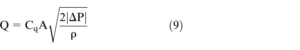
Where Q is flow.
The schematic of load sensitive priority valve is shown in Figure 6. During operation, the load sensitive (LS) line of the priority valve is always filled with oil, which feedbacks the working pressure to the spring cavity through a fixed damping hole. As the load pressure increases, the pressure difference between in and out oil port of the priority valve decreases, and the priority valve core shifts to the right. It will make the opening of the chief flow (CF) oil port become larger, the opening of the exceed flow (EF) oil port decreases, and the out-port pressure increases until the pressure difference in and out of the oil port returns to its original value. If the load becomes smaller, the adjustment process is the opposite. The load sensitive priority valve ensures a constant pressure difference between the in and out oil port, and its control accuracy is improved by the flow rate that is only directly related to the core displacement of the priority valve and is not affected by other factors.

The schematic of load sensitive priority valve.
Hydraulic system design
The technological scheme of the multi-mode steering hydraulic system is shown in Figure 7 which is consisted mainly of hydraulic steering pump, priority valve, hydraulic steering gear, control valve block, and hydraulic cylinder. The output flow rate of the fixed hydraulic pump enters the hydraulic steering through the priority valve. The LS line of the priority valve dynamically monitors the load of the steering circuit and feed it back to the left end of the priority valve. The output flow of the hydraulic steering gear enters the steering cylinder in turn through a reversing valve and a check valve block. Since the two steering hydraulic cylinders are in series, this requires the discharge port of reversing valve is able to withstand high pressure. The check valve block is utilized to lock the hydraulic cylinder position. The variable pump is an auxiliary pump that works during steering mode switching and is used to adjust the hydraulic cylinder to a suitable position without passing through the steering gear. The variable pump can adjust the speed by changing its own displacement. The variable pump has a large displacement when it is working to achieve the fast motion of hydraulic cylinder, and has a small displacement when it is not working only to maintain its own leakage. The two-ways reversing valve is used to control the oil path of the auxiliary pump, which is connected on the right side during the steering mode switch and connected on the left side in other working states.

The technological scheme of the multi-mode steering hydraulic system.
The steering switching rules are listed as following. In most cases, the four-wheel steering mode should be preferred. The four-wheel steering has the minimum steering radius. Since the front and rear steering cylinders are connected in series and the flow through the two cylinders is same, so the front and rear wheels have the same steering trajectory. In this way, rolling damage to crops by the wheels can be effectively reduced. Compared to the four-wheel steering system, the steering resistance force of the two-wheel steering is small. Because the steering center of front wheel steering and rear wheel steering is different, so the steering trajectory is quite different. The driver can choose the steering mode according to the actual conditions. In general, when the machine is aligned with the crop line, the rear wheel steering mode should be adopted. When the front steering space of the machine is insufficient, the front wheel steering mode should be adopted. This is mainly because that although the steering radius of the front wheel is larger than that of the four-wheel steering, but its steering center is relatively back. In addition, when switching steering mode is required, the driver must move the wheels to the middle position firstly for traditional steering system. This tedious operation is not necessary for the multi-mode steering system designed in this paper.
The designed hydraulic system has the following advantages. First and foremost, the hydraulic system can realize three modes of the front wheel steering, rear wheel steering, and four-wheel steering, and can switch quickly and flexibly between the three steering modes. Secondly, the load sensitive steering system has high control accuracy by ensuring that the flow through the priority valve is not affected by load changes. Thirdly, the auxiliary pump achieves the prompt response of the executing element and reduces overflow heat by changing its own displacement. In addition, the two steering hydraulic cylinders are connected in series to ensure better synchronization accuracy.
Parameters design of hydraulic system
Considering the actual load size, efficient work area of hydraulic components and other factors, refer to the hydraulic design manual, the design pressure is selected for 7.0 MPa and hydraulic cylinder diameter ratio is 0.5.
The piston diameter of the hydraulic cylinder can be calculated by formula (10). The maximum flow of the steering system and pump displacement can be calculated according to formulae (11) and (12).
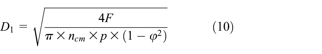

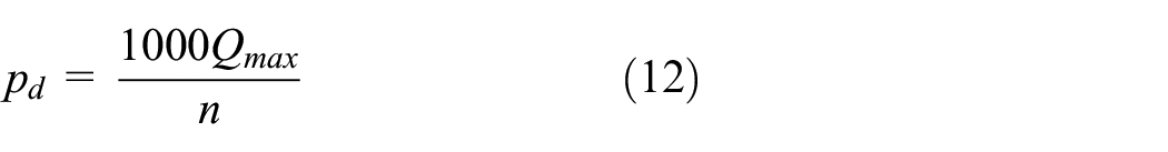
In the formulas,
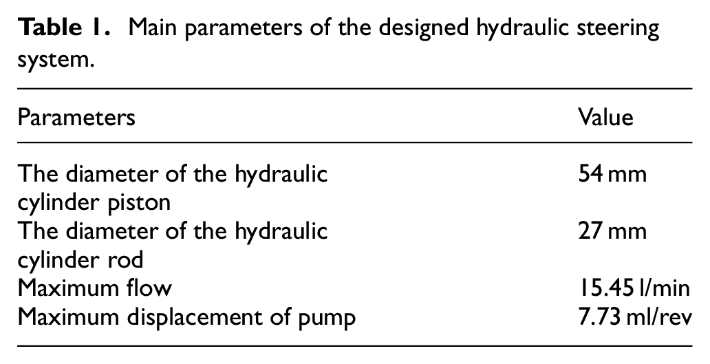
The main calculated parameters for the designed hydraulic system are listed in Table 1.
Main parameters of the designed hydraulic steering system.
Model establishment and simulation
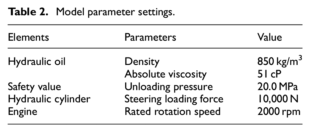
The mechanical-hydraulic-controlling coupling model established in the AMESim software is shown in Figure 8. The parameters of the hydraulic components are consistent with the above calculations (Table 1), and the other parameter settings of the model are listed in Table 2. There are three assumptions in the simulation. Firstly, pressure loss in hydraulic pipes is ignored. The actual hydraulic steering system has shorter pipes, so the pressure loss on the pipeline is small. Secondly, hydraulic oil temperature is always maintained at 50°C. In fact, the steering system does not work continuously for a long time, and the hydraulic oil temperature will not exceed 50°C.Thirdly, the friction of the hydraulic cylinder is not considered. Because the friction is quite small compared to the steering load force.

Simulation model in AMESim.
Model parameter settings.
Load sensitive system simulation
To verify the pressure-flow characteristics of load sensitive systems, the system parameters are simulated during load changes from 0 to 20.0 MPa. The parameters for non-load sensitive systems are equally simulated for comparison. The total simulation time is 10 s and the calculation step is 0.005 s. The pressure difference between in and out oil port of the valve and the flow variation curves through the valve are given in Figures 9 and 10, respectively.

The variation curves of pressure difference between in and out oil port of the valve.

The flow variation curves through the valve.
What stands out in Figure 9 is that for non-load sensitive system, the in and out of the oil ports pressure difference curve decreases linearly with the load pressure increases, while the in and out of the oil ports pressure difference fluctuates only slightly at the initial moment for load sensitive system. The pressure difference is always maintained at 7.5 MPa. Figure 10 illustrate that the flow trend is exactly the same as the change of pressure difference, which is also fully in line with the theoretical calculation. For load sensitive system, the flow through the valve is only related to the opening area under the condition that the pressure difference between the in and out oil port remains constant. If the load-sensitive system is not adopted, the actuator speed will be out of control when the external load pressure fluctuates. But the proposed load sensitive system can solve this problem well. It means the proposed scheme can maintain stability and improve control accuracy no matter how the load pressure changes.
Simulation of different steering modes
Two wheels steering simulation
The two-wheel steering mode includes front wheel steering and rear wheel steering, and since the difference between the two steering modes is only the execution of the hydraulic cylinder, so only one steering state parameters are simulated. The total simulation time is 8.0 s and the calculated step length is 0.01 s. The displacement of the two steering hydraulic cylinders is shown in Figure 11, and the pressure on the left and right working cavities of the performed steering hydraulic cylinder is provided in Figure 12.
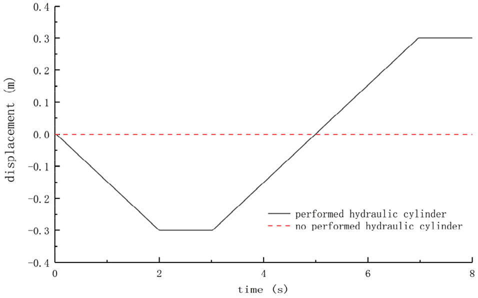
The displacement of the two steering hydraulic cylinders.

The pressure variation curves on the left and right working cavities of the performed steering hydraulic cylinder.
As is shown in Figure 11, displacement changes of the performed hydraulic cylinder linearly from 0 to −300 mm in 0–2.0 s and the its displacement changes linearly from −300 to 300 mm in 3.0–7.0 s. This performed cylinder is stationary for the rest time. The hydraulic cylinder that does not perform the steering always does not move. The Figure 12 is quite revealing in several ways. Firstly, the left working cavity pressure of the performed hydraulic cylinder in the 0–2.0 s is approximately 6.81 MPa, and the pressure has not reached a steady state at the initial moment. The right working cavity pressure is 0. In 2.0–3.0 s, the hydraulic cylinder travel reaches a negative maximum, at which point the relief valve is opened to discharge the load pressure and then the left working cavity pressure is equal to the relief valve discharge pressure of 20.0 MPa. Secondly, the steering hydraulic cylinder moves in the other direction, and the pressure of the right working cavity fluctuates to a certain extent and eventually stabilizing at about 6.81 MPa during 3.0–7.0 s. The left working cavity pressure is 0. After 7.0 s, the hydraulic cylinder travel reaches a positive maximum and the relief valve is opened to load-off. According to the simulation results, in two-wheel steering mode, the steering hydraulic cylinder has a moving speed of 150 mm/s and the operating pressure is 6.81 MPa approximately. These parameters meet the design requirements.
Four wheels steering simulation
The state parameters for four-wheel steering mode are also simulated, and the simulation parameters are set in the same way as above. The displacement and displacement error of the front and rear hydraulic cylinders are shown in Figures 13 and 14, and the pressure variation curves of the left and right working cavities of the front hydraulic cylinders are displayed in Figure 15.
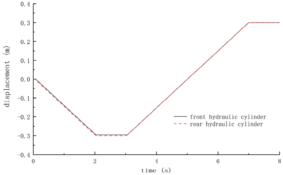
The displacement variation curves of the front and rear hydraulic cylinders.

The variation curves of displacement error of the front and rear hydraulic cylinders.

The pressure variation curves of the left and right working cavities of the front hydraulic cylinders.
In Figure 13 there is a clear trend that the displacement variation curves of the two hydraulic cylinders basically coincide throughout the whole process, indicating that the two series hydraulic cylinders have high synchronization accuracy. It is helpful to facilitates four-wheel steering to meet Ackman steering conditions. It can be seen from Figure 14 that, in 0–3.0 s, the displacement error of the two hydraulic cylinders fluctuates around 5.0 mm, mainly due to the fact that the initial system pressure has not yet reached a stable state, and the fluid flows through the two hydraulic cylinders with a certain lag. During the period of 3.0–8.0 s, the displacement error does not exceed 0.5 mm. The simulation results show that in the four-wheel steering mode, the displacement error between the two steering hydraulic cylinders is small, which meets the design requirements. In the designed hydraulic scheme, the two hydraulic cylinders are connected in series. The flow rate of both hydraulic cylinders is absolutely same if the hydraulic oil leakage is ignored. If the hydraulic cylinders are connected in parallel, the displacement error may become larger. The proposed system has better synchronization accuracy.
It can be known in Figure 15 that the working pressure of the left cavity is approximately 13.6 MPa and the working pressure of the right cavity is approximately 6.75 MPa during 0–2.0 s. The driving force should overcome the total loading resistance of the two series hydraulic cylinders, so the maximum operating pressure of the front hydraulic cylinder in four-wheel steering mode is approximately twice of that in two-wheel steering mode. At 3.0 s, hydraulic cylinder moves to another direction and left and right cavity working pressure has slight fluctuations. At last, the working pressure of the right cavity and the left cavity is stable at 13.6 and 6.75 MPa, respectively. After 7.0 s, the relief valve is opened and the right cavity is working at 20.0 MPa.
Simulation of mode switching state
The multi-mode steering system automatically adjusts the wheels to proper position without turning the steering wheel when switching in steering mode. The steering mode switching process is as following. A displacement sensor is mounted on each steering cylinder to dynamically obtain the travel. When the steering mode is switched, the controller automatically adjusts the position of the hydraulic cylinder to the appropriate position by using the proportion-integration-differentiation (PID) controlling algorithm based on the feedback data coming from the two displacement sensors.
In the PID control algorithm, the proportion coefficient (P), integral time constant (I), and differential time constant (D) are often obtained by trial and experience. In this paper, the optimal combination of PID parameters is sought through the SQCOA. The absolute value of the minimum displacement error between the front and rear hydraulic cylinders is taken as the target function, and the proportion coefficient, integral time constant, and differential time constant are taken as the optimization variables. The constraint conditions (c.c.) and target functions (t.f.) can be represented by formulae (13) and (14).


It can be calculated that when the proportion coefficient, integral time constant, and differential time constant are 29.840, 1.368, and 0.138, the displacement error of the front and rear hydraulic cylinders is the smallest. That means the system has the highest control accuracy. The displacement error data for different PID parameters are presented in Table 3.
The displacement error data for different PID parameters.

The status parameters of the two-wheel steering mode switching to the four-wheel steering mode are simulated. In 0–2.0 s, the system is in two-wheel steering mode, and the system is switched to four-wheel steering mode at 2.5 s. The two hydraulic cylinders displacement is shown in Figure 16, and the working cavity pressure of two hydraulic cylinders is shown in Figure 17.

The displacement variation curves of front and rear hydraulic cylinders.
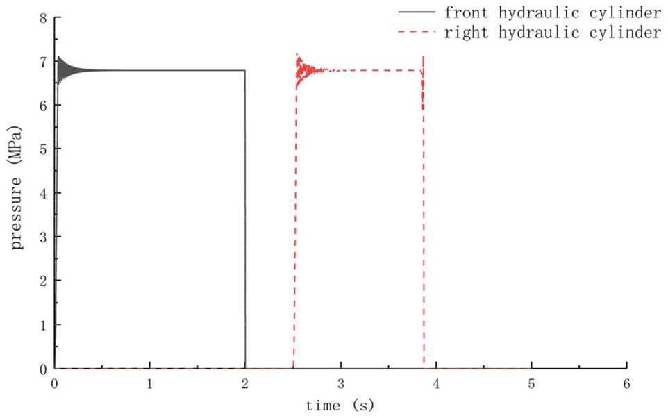
The pressure variation curves of working cavities of front and rear hydraulic cylinders.
It is apparent from Figures 16 and 17 that the hydraulic cylinder is moving at a constant speed of 150 mm/s, with its working pressure of 6.79 MPa, in a two-wheel steering mode. The hydraulic system switches from two-wheel steering to four-wheel steering at 2.5 s, and then another hydraulic cylinder, under the control of the PID algorithm, travels to 300 mm at the speed of 220 mm/s. At 3.83 s, the hydraulic cylinder displacement of front and rear wheel is basically equal, indicating that the system is adjusted to four-wheel steering mode. It should be noted that because the four-wheel steering mode and two-wheel steering mode switch to each other in the same way, so the four-wheel steering mode switch to two-wheel steering is no longer analyzed here.
Results
Experimental platform establishment
In order to analyze and verify the performance of the multi-mode hydraulic steering system, the test platform was researched and developed. The wheelbase and wheel pitch are 2150 and 1500 mm, respectively. The parameters of the hydraulic components are consistent with the design above. The front and rear wheel hydraulic cylinders are equipped with a pull-line displacement sensor to measurement displacement information. At the same time, the Smacq 3132 data acquisition card was adopted to dynamically captures displacement information and transmits it to the computer via USB communication. The sampling frequency is set to 10 Hz. The relevant parameters are listed in Table 4. The PID algorithm parameters are set as the optimal parameter combination obtained from AMESim calculation. The established experimental platform is presented in Figure 18.
The relevant parameters of displacement sensor and data acquisition card.


Experimental platform of multi-mode hydraulic steering system.
Displacement measurement
Hydraulic cylinder displacement in four-wheel steering mode and two-wheel steering to four-wheel steering was tested under dryland conditions after wheat harvest. The variation curves of two hydraulic cylinders displacement in four-wheel steering mode are displayed in Figure 19. In two-wheel steering mode, the driver turns the steering wheel in one direction and switches to four-wheel steering mode when the hydraulic cylinder travel reaches maximum. The Figure 20 demonstrate the variation curves of two hydraulic cylinders displacement during this process.
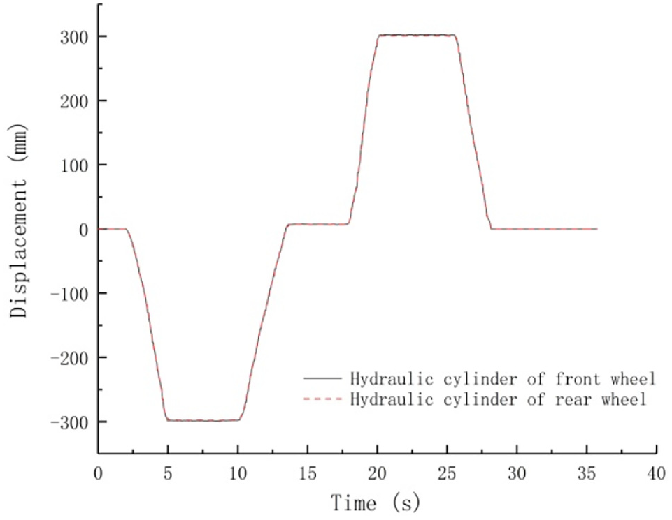
The variation curves of two hydraulic cylinders displacement in four-wheel steering mode.

The variation curves of two hydraulic cylinders displacement during the two-wheel steering mode switch to four-wheel steering mode.
As can be recognized from Figure 19 that displacement variation curves of the front and rear steering hydraulic cylinder basically coincident, which proves that the two hydraulic cylinders have better synchronization accuracy in four-wheel steering mode. The four-wheel steering mode meets the Ackman steering condition. In Figure 20, the front steering hydraulic cylinder operates at first, and reached to maximum displacement at 7.9 s. The system switches from two-wheel steering to four-wheel steering at 10.3 s, and then the rear steering hydraulic cylinder move quickly. At 11.8 s, the displacement of both front and rear steering cylinders is −300 mm.
Measuring experiment of steering radius
The steering radius test is performed in the field. Depending on the theoretical analysis, it can be learned that in two-wheel steering mode, the steering radius of the outer steering wheel can be calculated according to formula (15). In four-wheel steering mode, the steering radius of the outer steering wheel can be calculated according to formula (16).


In the formulas,
During the measurement process, the steering radius under different steering modes was measured three times, and then the average value was taken. The steering angle can be acquired in real time by an angle sensor. As the farmland surface is soft, the wheel tracks are clearly visible. Steering radius can be obtained by measuring wheel tracks parameters. The steering radius data are listed in Table 5 under the different steering angle of the outer steering wheels.
The steering radius data under the different steering angle.
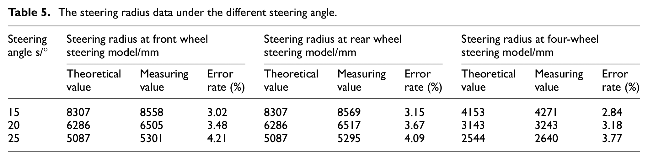
Table 2 illustrate that whether in two-wheel steering mode or four-wheel steering mode, the steering radius error rate increases with the increase of the steering angle of outer steering wheel. This is mainly due to the fact that the larger steering angle may cause the wheel slipping rate and increase the steering radius. The error rate of the front wheel steering and the rear wheel steering in different steering modes is basically coincident. The maximum steering error rate is 4.21% in two-wheel steering mode. The error rate of the steering radius at the four-wheel steering mode is less than that of the two-wheel steering mode at the same steering angle. This is mainly due to the same wheel trajectory of front and rear wheels under the four-wheel steering model, which reduces the wheel slip to a certain extent. In addition, the same wheel trajectory reduces crush damage to the crop. The maximum steering error rate is 3.77% in four-wheel steering mode.
Discussion
An initial objective of the project is to improve the steering flexibility of agricultural machinery in hilly and mountainous areas. But very little was found in the literature on the development of multi-mode steering system. So a new kind of multi-mode steering system of agricultural machinery for hilly and mountainous area was designed and analyzed in this paper. It differs from the previous literature that the multi-mode steering system can achieve three steering modes: front wheel steering, rear wheel steering, and four-wheel steering. The load sensitive system was adopted which can ensure that the flow through the priority valve is not affected by load changes, and it is positive to improve flow control accuracy. The PID algorithm is also employed to switch two-wheel steering to four-wheel steering mode and the optimal combination of PID parameters is sought through the SQCOA. When the proportion coefficient, integral time constant and differential time constant are 29.840, 1.368, and 0.138, the controlling system has the highest control accuracy. The steering radius measurement was also conducted. The maximum error rate of is steering radius 4.21% and 3.77%, respectively, in two-wheel steering and four-wheel steering modes. These findings suggest that the designed the front and rear hydraulic cylinders have good synchronization accuracy in four-wheel steering mode, and the fast switch of steering mode can be realized. These data are match those observed in earlier studies and further support the idea that the four-wheel steering will reduce the slipping rate to a certain extent. However, the average slipping rate is measured in this paper and the transient slipping rate is ignored when the vehicle is steering. Further studies, which take these variables into account, will need to be undertaken.
Conclusions
Most of the existing agricultural machinery can realize front wheel steering and a few can achieve four-wheel steering, which greatly limits the steering flexibility of agricultural machinery. The problem is more pronounced in the hilly and mountainous regions which have a large number of small fields. A multi-mode steering system with front wheel steering, rear wheel steering, and four-wheel steering of agricultural machinery for hilly and mountainous area was designed and analyzed in this paper. Four-wheel steering can provide the minimum steering radius. Moreover, the front and rear wheel track are same, which can reduce the rolling damage to crops. Two-wheel steering has less steering resistance force. The steering center of front wheel steering and rear wheel steering is different and the driver can choose the steering mode according to the actual conditions. The four-wheel steering adopts series-wound hydraulic cylinders, so the front and rear steering hydraulic cylinders have better synchronization accuracy. When the steering mode is switched, the hydraulic system has good control accuracy and response rate with PID control algorithm.
The multi-mode steering hydraulic system based on the load sensitive system was designed which can ensure that the flow through the priority valve is not affected by load changes. Subsequently, the mechanical-hydraulic-control coupling model was established in AMESim and the system parameters were simulated in different steering modes. The simulation results are quite revealing in several ways. Firstly, in two-wheel steering mode, the steering cylinder has a moving speed of 150 mm/s and its operating pressure is approximately 6.81 MPa. Secondly, the maximum operating pressure of steering hydraulic cylinder is 13.6 MPa. Last but foremost, the PID control algorithm is adopted to switch two-wheel steering to four-wheel steering mode and the optimal combination of PID parameters is sought through the SQCOA. It can be calculated that when the proportion coefficient, integral time constant, and differential time constant are 29.840, 1.368, and 0.138, the controlling system has the highest control accuracy. In order to examine and verify the performance of the multi-mode hydraulic steering system, the test platform was researched and developed. The experimental data illustrated that the front and rear hydraulic cylinders have good synchronization accuracy in four-wheel steering mode, and the fast switch of steering mode can be realized. The steering radius measurement was also conducted. The maximum error rate of is steering radius 4.21% and 3.77%, respectively, in two-wheel steering and four-wheel steering modes. The experimental data show that the designed steering system meets the design requirements and can effectively improve the steering flexibility of agricultural machinery.
Footnotes
Handling Editor: James Baldwin
Declaration of conflicting interests
The author(s) declared no potential conflicts of interest with respect to the research, authorship, and/or publication of this article.
Funding
The author(s) disclosed receipt of the following financial support for the research, authorship, and/or publication of this article: This work has been supported by the Research and Development Program of Chinese Academy of Agricultural Sciences (Grant no. CAAS-NRAM-SJ-201903). And partly supported by Basic Scientific Research Project of Nanjing Research Institute for Agricultural Mechanization Ministry of Agriculture and Rural Affairs (Grant no. S201907) and the National Research and Development Plan (Grant no. 2017YFD0700704).