
Abstract
Modular design, Axiomatic design (AD) and Theory of inventive problem solving (TRIZ) have been increasingly popularized in concept design of modern mechanical product. Each method has their own advantages and drawbacks. The benefit of modular design is reducing the product design period, and AD has the capability of problem analysis, while TRIZ’s expertise is innovative idea generation. According to the complementarity of these three approaches, an innovative and systematic methodology is proposed to design big complex mechanical system. Firstly, the module partition is executed based on scenario decomposition. Then, the behavior attributes of modules are listed to find the design contradiction, including motion form, spatial constraints, and performance requirements. TRIZ tools are employed to deal with the contradictions between behavior attributes. The decomposition and mapping of functional requirements and design parameters are carried out to construct the structural hierarchy of each module. Then, modules are integrated considering the connections between each other. Finally, the operation steps in application scenario are designed in temporal and spatial dimensions. Design of cutter changing robot for shield tunneling machine is taken as an example to validate the feasibility and effectiveness of the proposed method.
Keywords
Introduction
In order to adapt to various customer demand and changing market orientation, new products have to improve the efficiency and innovation in concept design to enhance their competitiveness. Conceptual design method provides theory and guidance for design activities, largely affecting the design result of product. Therefore, a multitude of conceptual design approaches have been put forward to provide solution for a wide variety of problems encountered in the design process, including problem analysis and idea generation. Problem analysis tools comprise Axiomatic Design (AD), Quality Function Deployment (QFD), and Total Quality Management (TQM). While the tools of idea generation include Brainstorming, Mind Mapping, and Theory of Solving Inventive Problems (TRIZ).1,2 All above mentioned methods own different merits and disadvantages.
In general, modular design method is widespread used in large-scale engineering machine design with the advantages of reduced complexity, reduced design period, rapid product development, and diversified design solutions. Most researches focus on modular partition and combination methods, which directly determine the design scheme. Teng et al. 3 put forward a module partition approach through fuzzy clustering algorithm and has been applied to ship design. It only considered the connective compactness between components, and the technical equipment and surrounding environment has not been taken into account. Bai et al. 4 conducted module partition after functional decomposition, which focused on module interface structure, comprehensively considering the fuzzy relationships of functional requirements. Li et al. 5 put forward a module division and scheme evaluation method based on dynamic clustering diagram and TOPSIS. Module classification and evaluation of computer numerical control machine are completed after its establishing product structure model. Hong and Park 6 used design structure matrix to define the modules of the product based on function structure diagram, generated design scheme does not contain any information about spatial relationships among modules. The modular design method above-mentioned are mostly applied to improve or redesign existing product, taking full advantage of functional, and physical relationships among components, while it is not applicable to new product design. When designing a large new product/mechanical system in conceptual design stage, it is difficult to find the relationship between potential functional requirements and design parameters with less information. Therefore, designers may need careful consideration or introduce other tools to modular design a new large product.
Axiomatic design is a principle that guides designer understanding the design problems and establishing a scientific framework for the creation process of products through mapping and zigzagging process.7–10 But it does not provide specific techniques for generating efficient design solutions. Therefore, Method to generate innovative design solutions should be introduced. TRIZ was created in 1946 by Altshuller, 11 which effectively unveiled the common features of paradoxical and conflicting demands between creative patents. It focuses on the exaggeration and settlement of internal contradictions to obtain ideal solutions based on 40 inventive principles and 39 standard engineering parameters.12–14 TRIZ specialize in generating innovation ideas during new product development. In a word, AD focus on transition between functional requirements and physical structure, but cannot improve the innovative of product. While TRIZ provides a systematic thinking way with knowledge foundation to generate breakthrough ideas, but cannot offer a thorough design process from idea to structure. To reduce these drawbacks, TRIZ and AD method are integrated to improve the efficiency and quality of the product design process, which have been increasingly popularized in the engineering and technical product design.5,6 Related researchers have proposed a variety of hybrid design methods based on different combination and sequences of TRIZ and AD.15–17 Wu et al. 18 adopted TRIZ tools to solve the contradiction from the zigzagging and mapping process between FRs and DPs, where the contradiction is difficult to identify for the new product design. Li et al. 19 proposed the integration of MBR, AD, and TRIZ to support product design under incomplete information environment, where TRIZ is employed to settle the technical and physical contradictions between product attributes. But the contradiction between PAs fails to be determined quickly and accurately without enough detail information. Bai et al. 4 used AD to analyze the coupling relationship between the module interface and the functional requirements and then adopted TRIZ tools to decouple. It is not easy to find the relationship between potential functional requirements and design parameters. Ko 20 presented a novel hybrid approach and operational compact matrix by integrating TRIZ and AD into the conceptual design activities of new product design, helping designers generate more conveniently and effectively creative outcomes. In conclusion, how to quickly and accurately identify the contradictions in the design process has not been solved in the existing TRIZ and AD integration methods, which is also the key to affect the quality of design activity of new product. It is unavoidable to get coupled design when designing large-scale mechanical system with multi-hierarchy decomposition by TRIZ and AD method. Corresponding TRIZ tools should be applied to handle coupled design many times to keep all FRs independent with each other, which make the design process tedious, and complicated. Therefore, module division is introduced to the design process. Firstly, the big mechanical system is separated into several independent modules, then decomposition and mapping process of each module are conducted. It can greatly reduce the workload and complexity of design process.
In conclusion, it is indispensable to propose a systematic design approach for improving the quality of problem analysis and solution generation process. This paper tries to develop a systematic and comprehensive integrating the modular design, AD, and TRIZ efficiently, aiming at innovative design of large-scale mechanical system. Firstly, the customer need and total function requirements of the new product are determined, then the new product/mechanical system is divided into several modules based on scenario decomposition, and the large design problem is divided into several small manageable sub-problems. The working process of each module are divided into behavior segments. The behavior attributes model of each behavior segments is established, including motion form, spatial constraints and performance requirements. TRIZ tools are employed to deal with the contradictions between attributes. Then, the mapping and zigzagging processes between the functional domain and physical domain of AD are carried out to construct the design parameter hierarchies of each module. The designed modules are assembled into a large system based on the connection model between modules including spatial, energy, material, and information relations. Finally, the detail operational steps of the designed mechanical system are designed satisfying the time order and space continuity. Importantly, design of cutter changing robot for shield tunneling machine is taken as an example to validate the feasibility and effectiveness of the proposed method.
Methodology
As for a complex system, it is difficult to analyze key problems quickly and accurately. Modular design is adopted to reduce the design period. To create an innovative and complete design, integration TRIZ and AD approaches are developed to generate innovative concepts for new product. The framework of proposed method is presented in Figure 1, which is mainly divided into module partition, module design and module combination.

Workflow of the proposed approach.
Module partition
Large-scale complex system is usually divided into modules according to some rules after analyzing the collected information of product. The basic product information includes design requirements and function requirements. If the information is complete, the product is easily divided into modules with independent function. When the relative information of product is incomplete and unclear, scenario decomposition is employed to Module partition by analyze the relationships between action steps in terms of time and space. Related parts with closely relationships are integrated and defined as independent modules. It decomposed the complex system into several small and independent modules. The detail process is as follows.
Step 1: The customer needs of the product are summarized by analyzing the potential problems of the existing product and operation.
Step 2: The design task
Step 3: Scenario decomposition is adopted to divide the whole operation process into multiple plots in a rational and complete way.
Step 4: Analyze the operation characteristic, surrounding constraints of the parameters such as space, motion, force for each plot.
Step 5: Plots with reversible behavior in the same spatial location are defined as independent modules. The complex mechanical system

Module design
Step 1: The working process of each module are divided into several behavior segments.

Where,
Step 2: The behavior attributes model of each module is established, which includes motion form, spatial constraints and performance requirements. It provides good heuristics on the direction for the functional decomposition. 21
Where,
Step 3: Judge whether there is conflict between behavior attributes of the module. If there are conflicts between behavior attributes, TRIZ tools are employed to settle the design problem and generate innovative ideas. Firstly, specific technical contradiction of the module is recognized, by analyzing, some technical indicators are expected to improve while other technical indicators will be deteriorated at the same time. Then, the specific technical contradiction of the module is translated to TRIZ generic problem, where the indicators are translated into improving parameters and worsening parameters according to 39 general engineering parameters. Afterwards, based on identified general engineering parameters and 40 invention principles of TRIZ, a set of general recommendations for resolving the general contradictions are identified. Contradiction matrix of the module are constructed, where improving parameters are on the left column, worsening parameters are on the top row, and the TRIZ generic solutions are at the crossing cells. Finally, the most suitable suggestions are selected from the suggested invention principles, which are translated into specific solution that can solve the initial technical contradiction. Finally, an innovative solution of module contradiction during design process is generated.
Step 4: Mapping process from functional requirements (FRs) to design parameters (DPs) and Decomposition of FRs and DPs at each hierarchy are conducted by means of AD. Continuously repeat mapping and decomposition until FRs cannot be decomposed anymore. The FRs of the sub-level are determined by the characteristics of the DPs in the upper-level and the DPs of the sub-level are selected to satisfy the corresponding FRs at the same level in the zigzagging process, where the motion form, spatial constraints, and performance requirement attributes of each behavior segments are taken into consideration. Hierarchies of FRs and DPs are generated during the zigzagging. The relationship between FRs and DPs at each level of hierarchy are characterized as follows.

Where,

The design matrix at each level of hierarchy should satisfy the independence axiom. The design matrix can be categorized into uncoupled, coupled, and decoupled design. As coupled design violates the independence axiom, TRIZ tools are adopted to solve the design problems.
Step 5: The functions and design parameters of each modules are obtained.
Module combination
After completing the detail design of each modules, the detail design and the geometrical model is presented. All modules constitute a system through some relations, rather than simple summation, which can be demonstrated by

Where, ⊕ is the relation among modules, which act as a bridge to integrate all modules into a synthesis.
The connection between modules includes spatial, energy, material, and information relations,

Where,
Process design
The geometric model of the whole product as well as surrounding environment and the working object is established after module combination. The designed product is placed in the application scenarios to visualize the actual operation process of the designed product. Based on the behavior segments, behavior attributes model and the design parameters of each module, the operation process of the product is designed to improve the operation efficiency of the product, on the premise of satisfying the time order, and space continuity.
Case study
The cutter changing robot (CCR) is demanded in the slurry shield machine to improve the efficiency and safety of construction, taking the place of manual cutter changing operation. Complex operation surroundings and tedious procedures make the design of CCR challenging. The presented method is applied to the design of CCR to validate its practicability and effectiveness.
Module partition
Identify the customer needs
As the core part of shield tunnel boring machine, cutter directly cuts the soil in the tunneling face, playing the role of cutting the rock. Particularly for the excavating with long distance, it would unavoidably lead to severe wear and fracture failure.22,23 If the worn cutters could not be changed in time, it would increase the cutter consumption and extend the construction period. Therefore, replacing the worn cutter is an inevitable work during construction.24,25
Under complex geological conditions, specialized workers are needed to renew worn cutters in the narrow excavation chamber frequently with high pressure, as shown in Figure 2. It might increase the risk of workers’ safety and even result in major accidents.26,27 Manual cutter changing operation requires operators to enter the excavation chamber carrying lighting and hoisting tools under tough environment with high temperature, high humidity, and high pressure. 28 Moreover, the structure and connections between cutter and cutter housing is complex. The traditional cutter and cutter housing system includes inner housing, wedge block, bolt, press block, nut, gasket, and locating pin, as shown in Figure 3. The cutter is locked by these components to achieve the load transferring. 29 Thus, the traditional manual cutter changing method is cumbersome with a range of steps. Initially, the worn cutter was clamped by claws and then got lift by chains. By applying specific tools, the bolt would get loose. Following with the removal of the wedge block, press block, and bolt, the cutter would be pulled out of the housing from groove. Finally, the cutter would be moved to the back. Similarly, the new cutter would be installed in the cutter housing with the same procedure. The total operation process is shown in Figure 4.

Manual cutter changing operation.

Components of cutter installation.

Traditional manual cutter changing process.
The traditional cutter installation manner and manual cutter changing operation with high risk and low efficiency cannot meet the requirement of tunnel construction. Therefore, an automatic CCR is urgently designed to improve the safety and the efficiency of operation in slurry shield machine. Due to the complexity of traditional cutter installation structure and its operation, it is challenging to design corresponding installing and disassembling robot. However, the structure and installation manner of cutter housing system is eager for an innovative design.
In conclusion, the target customer is tunnel construction unit. CCR is expected to replace manual cutter changing operation, reducing construction risk. And quick cutter changing operation can shorten the time of inspection and maintenance. Moreover, the CCR should adapt to different shield tunneling machine for tunnel construction.
Determine the total function
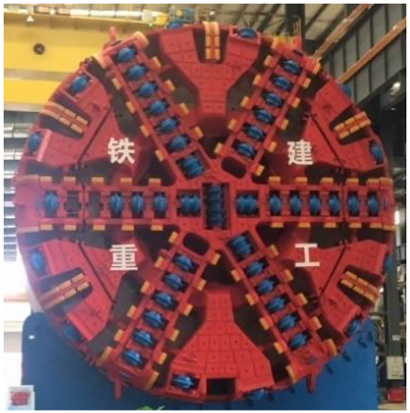
As the CCR is built in the slurry shield machine, the compliance with slurry shield machine should be taken as the crucial consideration during CCR design process. The internal space of large-diameter slurry shield machine is the workspace of the CCR, If the CCR is arranged at the rear of cutterhead. As shown in Figure 5, the slurry balance cabin is the region between cutterhead and front cabin plate, while air cushion cabin is the space between front cabin plate and pressure plate. Numerous cutters are installed in a specific cutter housing, which is welded on the plate of cutterhead,
30
as shown in Figure 6. The target position of CCR is determined by the arrangement characteristic of cutter, including installation radius, installation angle and inclination of cutters.31,32 According to the situation analysis of application scenarios and target objects of CCR, the functional requirements of CCR design
Automatically lock and disassemble the cutter from the cutter holder with simple and few actions.
Transport the heavy cutter to any location on the cutterhead steadily in the specific workspace, avoid collision with the internal structure in the slurry shield machine.
Exchange the worn cutter and new cutter in a storage cabin located at the back of the cutterhead.

The motion range of CCR.
Cutters layout of cutterhead.
Module partition
Removing the worn cutter from cutterhead and installing a new one is the whole task of CCR. As shown in Figure 7, the whole cutter changing process could be decomposed into eight scenes, including moving from storage cabin to the worn cutter position, removing the worn cutter, clamping the worn cutter back to the storage, putting down the worn cutter, clamping the new cutter, moving to the new cutter position, installing the new cutter then moving back to the storage cabin. As the dismounting and installing cutter process is reversible, and all of actions are completed in the inner space of cutter housing. Therefore, the dismounting and installing device is set as an independent module of CCR, which should be designed according to cutter and cutter housing structure characteristics. The motion of CCR in slurry balance cabin could be summarized as the transport module, whose motion range depends on the excavation diameter of the shield tunneling machine and cutter layout characteristic. It is expected to put down and clamp cutter at the rear of shield tunneling machine, which is set as exchanging module. In conclusion, the CCR could be regarded as three modules, including operation module

Scenario decomposition of cutter changing operation.
Module design
Operational manipulator module design
The function of the operational manipulator module is to remove the connecting components and take the cutter outside from the cutter holder. The function of the operational module is divided into several behavior segments. As shown in Figure 8, the operational module includes four behavior segments, extruding into cutter holder

Behavior segments of operational module.
Behavior attributes model of operational module.

According to behavior attributes model of the operational module, the design contradiction between performance requirements and spatial constraints can be clearly identified. After analyzing the problem of operational manipulator during design process, improving these given parameters may affect other parameters negatively and this needs to be avoided. Improving parameters (IP) and worsening parameters (WP) are identified to construct a contradiction matrix and obtained the principles of TRIZ resolution.
In order to innovative design the operational manipulator module, several parameters should be improved. The operational manipulator is designed to achieve the disassembly, installation, and grip cutter task, which could be regarded as reliability (No.27). The operation is required to be as simple as possible with fewer steps to enhance the efficiency of cutter disassembly and installation, which refers to the operability (No. 33). Furthermore, the operational manipulator should adapt to the cutter structure, cutter holder structure and space, fastening structure characteristic during cutter changing process, which is classified as the adaptation (No. 35). The operational manipulator is supposed to complete the cutter changing actions as soon as possible, which is classified as the productivity (No. 39).
When improving specific parameters, corresponding concerns and conflicts are taken as WP. The operational manipulator is installed at the end of the robot. Therefore, the weight of the operational manipulator should meet the load limitation of transport device, which refers to the weight of moving objects (No. 1). When operational manipulator working, it is necessary to avoid collision with the cutter and cutter housing. It indicates that the operational manipulator should be shaped with relatively small size to fit the room of cutter holder which refers to the volume of moving object (No. 7). The shape of operational manipulator should satisfy the space characteristic to complete the actions, which refers to the shape of the objects (No. 12). Moreover, fewer components of operational manipulator are required to connect with each other simply, which refers to the complexity of the device (No. 36).
The general parameters of expected improvement and deterioration are obtained based on conflict analysis of operational manipulator. As shown in Table 1, the contradiction solution matrix is constructed. The first column illustrates IPs, while the first line shows the WPs. The TRIZ-based contradiction matrix of this case was constructed as shown in Table 2. According to the extracted problems, invention principles were chosen. No.1 (segmentation), No.2 (extraction), No.5 (combination), No.9 (pre-action), No.24 (mediation), No.35 (transformation of properties). These principles provided a design direction of systematic resolutions and indicated the new structure required in the new CCR.
Contradiction solution matrix of operational manipulator module.

The selected invention principles are adopted to solve the problem during design process of operational manipulator. Based on segmentation principle, the operational manipulator is divided into two independent parts, which are installation device and gripping device. Installation device is arranged at the joint of cutter shaft and cutter housing, while the gripping device is placed at both side of cutter ring, completing their own assignment independently. Based on extraction principle, several useless parts such as positioning pin, nut, and gasket are extracted in order to reduce the complexity of the device. According to the combination principle, the combining utilization of wedge block, pressure block, and bolt could guarantee the reliable connection. The motion of bolt could be transferred to the pressure block and wedge block to complete the dismount and install of cutter. According to pre-action principle, the leverage is designed to transfer force efficiently for the cutter gripping. Linkage mechanism is introduced as mediation to change the motion direction of gripping action. The operability of operational manipulator would be improved.
After solving the conflict of operation device by means of TRIZ, the mapping of function and design parameters are completed based on AD design theory. The cutter operation function

The set of FRs and DPs for operational manipulator module.


Hybrid matrix of the innovative operational manipulator module.
The geometric model of operational manipulator is established, as shown in Figure 10, the operational manipulator includes shaft connects, pressure block, side slider, hexagonal bolt, claw, claw connects, linkage, and telescopic cylinder. In terms of disassembly mechanism, the shaft connects are connected with the shaft of cutter by bolts, while the side slider is connected with the shaft connects through sliding chute. In addition, with a hollow area at the center, the pressure block enables the inside motion of the hexagonal bolt. It could be found in the figure that cutter disassembly device enters the cutter housing from the backside of cutterhead. Then the vertical movement of pressure block derived from the hexagonal bolt rotating, could be converted to horizontal shift of side slider, by which the installation and disassembly of cutter would be completed. In regard to the clamping device, the lower part of claw is matched with the profile of the cutter to reliably clamp the cutter. The top of the claw is connected with the linkage, whose another end is connected with the telescopic cylinder. Through the up and down movement of the telescopic cylinder, the claw could spin with the claw connects to achieve the clamping and releasing actions. These two mechanisms above-mentioned are independent in space but cooperative in cutter changing operation.

Detail design of operational manipulator.
Transport module design
The function requirement (FR) at the top level in the hierarchy can be represented as
As shown in Figure 11, the transport module includes four behavior segments, including moving along the axis

Behavior segments of operational module.
Behavior information model of transport module.

In order to reach the position of cutters on the cutterhead for replacement as soon as possible, the length of moving object (No. 3) and the action time of moving object (No. 15) need to be improved. However, this may lead to collision with internal structure of slurry shield machine, “the adaptability and versatility (No. 35)” may be getting worse. In addition, the transport module is designed to carry the heavy cutter and operational manipulator. It means the strength of object (No. 14) needed to improve. But the weight of transport module and operational manipulator may be increased, which refers to the weight of moving object (No. 1). When the transport module is shut down, it should be placed in the storage cabin, which requires to improve the volume of moving object (No. 7). Nevertheless, the reliability of the object (No. 27) may be worse.
The IPs and WPs of transport module are identified to construct a contradiction matrix, as shown in Table 5. The first column illustrates the expected improvement parameters, while the first line shows the worsen parameters.
Contradiction solution matrix of transport module.
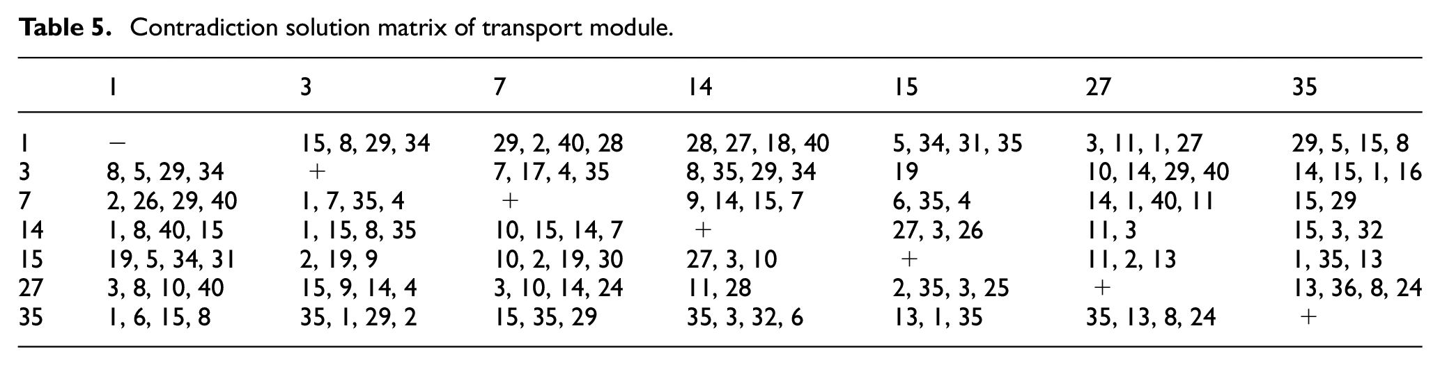
Combined with the real problem of transport module design and the contradiction solution matrix, No.1 (segmentation), No.7 (nesting), No.13 (reverse), and No.15 (dynamic) invention principles are adopted to resolve the conflicts. Based on segmentation principle, the transport module is divided into several joints with different motion functions. Each joint could adjust the relative posture to get approach to different cutter locations. The transport module is flexible and easily operated. Following the principle of nesting, a telescopic mechanism is designed to expand the motion range of transport module. It could be contracted during the off-time. Based on reverse principle, the cutterhead rotates to the position close to the storage cabin before operation. It could greatly shorten the movement path of the transport module. According to the dynamic principle, the sliding seat is connected with the storage cabin. When working, the sliding seat would get extent to the cutterhead, which reduce the moving distance of the transport module and improve the reliability of the transport module.
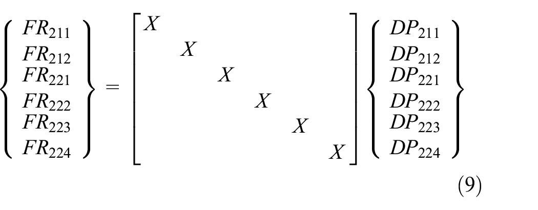
The contradiction of transport device is solved by means of TRIZ theory, then the function-structure mapping model is established by AD theory. The transport function
The set of FRs and DPs for transport module.


Hybrid matrix of the innovative transport module.
The cutter transport device includes sliding seat, pitching mechanism, rotating seat, flipping mechanism, telescopic mechanism, and swing mechanism, whose geometric model is shown in Figure 13. The transport module is horizontally placed on the bottom of storage cabin through the sliding seat so that it could slide inside and outside. The pitching mechanism, which is connected to the sliding seat, which can pitch within a certain range to expand the motion range of transport module. Above the pitching mechanism, a rotating seat is attached to determine the motion direction with the full rotation. The rotating seat is also jointed with the flipping mechanism which is able to flip forward and backward. Besides, connected to the flipping mechanism, the telescopic mechanism could adjust the length to reach the target cutter. Then the swing mechanism that is used to allow the operational manipulator into the cutter housing by adjusting the swing angle, is arranged at the front of the telescopic mechanism. When working, the cutter transport module could reach most space of the cutter without collision with other structures. When not working, it could be contracted in the storage cabin. On the whole, this device shows good performance of flexibility and adaptability.

Detail design of cutter transport device.
Exchange module design
The function of the exchange device is automatically replacing the worn cutters with new cutters. The behavior segments of cutter exchange process are shown in Figure 14, which contains four segments, handovering the cutter

Behavior segments of cutter exchange module.
Behavior information model of exchange module.

According to TRIZ theory, parameters of exchange module expected improvement are listed. When taking the cutter from the operational manipulator, the handover device is required to bear the weight of cutter, which means that the strength of object (No. 14) should be improved. It may have worsening effect on the volume of moving object (No. 7). The moving device is required to complete the motion between operational manipulator and placing device quickly which refers to the action time of moving object (No. 15). At the same time, the complexity of the device (No. 36) may get worse. As for the placing device, the reliability (No. 27) of the cutter placement need to be improved. And it should fit the structure characteristic of cutter and handover device to get rid of the interference, which represents the adaptability of the object (No. 35).
The general parameters of improvement and deterioration are obtained based on conflict analysis of exchange module, and the contradiction solution matrix is constructed, as shown in Table 8.
Contradiction solution matrix of exchange module.

No.7 (nesting) invention principle is adopted in the design of handover device. The handover device is designed to be telescopic. The handover device is moving with contractive state, while it is holding the cutter, the state becomes to be extended. No.15 (dynamic) principle is adopted in the design of moving device. The moving device is set with three directions, whose relative location is adjustable. No.13 (reverse) principle is applied in the design of placing device, where the placing device consists of a mobile one and a fixed one to avoid collision while placing.
The contradiction of exchange device is solved by means of TRIZ theory, then the function-structure mapping model is established by AD theory. The whole process could be regarded as three parts which are handover

The handover device

The set of FRs and DPs for operational manipulator module.

Hybrid matrix of the innovative exchange module.
The cutter exchange device includes crossbeam, translation column, right-angle seat, telescopic link, fixed rack, and mobile rack, whose geometric model is shown in Figure 16. The worn cutter would be disassembled and delivered into the storage cabin, after the new cutter exchange. The crossbeam could move back and forth at the top of storage cabin. While the translation column could move left and right under the crossbeam. Additionally, the right-angle seat can move up and down in the groove of translation column, the transport process between worn cutter and new cutter could be completed through combined movement along three directions. The right-angle seat is connected with the handover device, which consists of the telescopic link and saddle. When handovering the cutter, the telescopic link extends to the cutter location. The saddle contacts with the bottom surface of cutter to support the weight. The cutter placing device includes a fixed rack and a mobile rack. The fixed rack is arranged at the rear of the storage cabin, while the mobile rack could move forward and backward. When the cutter is descending, the mobile rack would move to the forefront. After the cutter bottom surface contacts with the top surface of the fixed rack, the mobile rack would move back to the lower of cutter to hold the cutter. The cutter exchange process is simple and convenient, which makes the whole cutter changing process efficiently and continuously.

Detail design of cutter exchange device.
Module combination
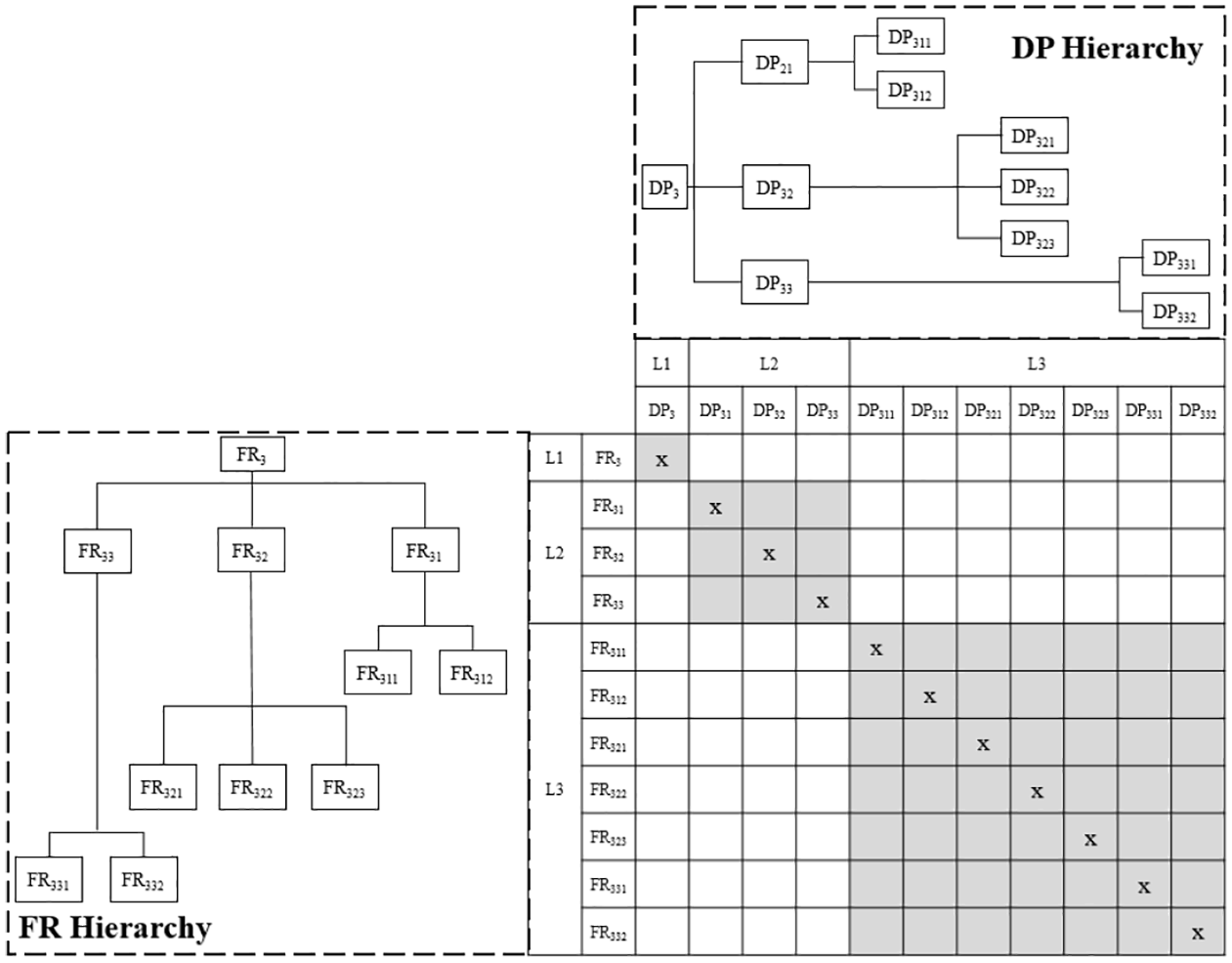
The three modules of the CCR is designed by integrating TRIZ and AD approach, and the DP and FR hierarchies are constructed, as shown in Figure 17.

Hierarchies of cutter changing robot: (a) FR hierarchies of cutter changing robot and (b) DP hierarchies of cutter changing robot.
The module connection model of three modules is established, including spatial, energy, material and information relations. As shown in Table 10.
The connection model between modules of CCR.

And the modules are combined as an integral system in sequence and placed into the slurry shield machine, as shown in Figure 18. The specific operation scenarios of each module are presented to validate the proposed model.

Module combination of cutter changing robot.
Process design
The operation process of the CCR are displayed in Figure 19, where the time order and space continuity are taken into consideration. Firstly, the cutterhead stops turning and discharges the soil. The position of cutter to be replaced is marked. And then, the door of air cushion cabin and CCR storage cabin are opened consecutively. Subsequently, the CCR moves out of the cabin and reach the cutter position through transport device. Then, the worn cutter is dismantled and taken out of the cutter by operational device. Afterwards, CCR returns to the storage cabin with the cutter. The exchange device is used to place the worn cutter and grab the new cutter. Then, CCR moves out of the cabin with new cutter, and arrives the cutter holder position. Installation and locking cutter are conducted by operational device, then CCR returns to the cabin, which means the whole process of changing a cutter is completed. If there are other cutters need to be replaced, CCR move out of the cabin again. If all cutters are replaced, the door of air cushion cabin and CCR storage cabin are closed consecutively.

Cutter changing process flow of cutter changing robot.
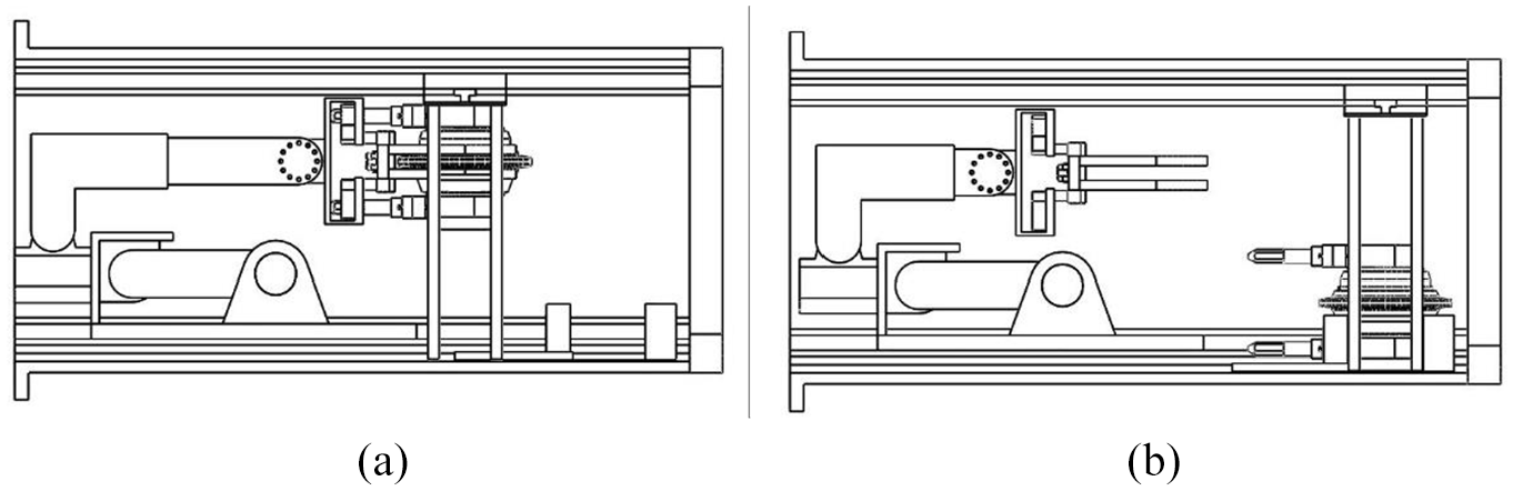
The main steps of cutter changing process are highlighted. Dismantling and installing cutter process is completed by operational device, whose main structure is install mechanism and clamping mechanism, as shown in Figure 20. And transferring the cutter from the storage cabin to the cutterhead is conducted by transport device. When changing the cutter at different position, the transport device has different movement paths and postures, as shown in Figure 21. The exchanging cutter process is also an important step of cutter changing process, which includes taking the cutter from the operational device and placing the cutter, as shown in Figure 22.

Dismantle and install cutter process: (a) dismantle and grab the cutter and (b) install and locking the cutter.

Postures of CCR when changing the cutter at different positions: (a) changing the cutter with the maximum radius and (b) changing the cutter with the minimum radius.
Cutter handover process in storage cabin: (a) handover cutter and (b) place the cutter.
Conclusion
A novel and systematic conceptual design approach using an integration of TRIZ, AD and modular design is developed and successfully applied to the conceptual design of CCR. In the module partition stage, scenario decomposition is used to divide the big complex cutter changing system into three independent and cooperative modules, which largely reduced the design period and complexity. Each module can be designed according to the characteristics of the shield machine to improve the applicability of the CCR. In the module design stage, the module is decomposed into behavior segments, whose attribute model are established in the aspect of motion form, spatial constraints and performance requirements. The contradiction between behavior attributes are easy to identify. Then, the generalized parameters and corresponding solutions of TRIZ is applied to solve the contradiction and deliver innovative solutions smoothly. By adopting the AD approach, the interdependency of FRs and DPs can be completely analyzed and hierarchically constructed in design process. In the module combination stage, proposed modules are grouped into a complete system well-regulated, where the spatial, energy, material, and information relations between modules are taken into consideration. Finally, the operation process of CCR is visualized in time orderly and space orderly, aiming to check whether the designed product can realize the overall function. It is expected that the modular design method integrated TRIZ and AD can be applied to the design of complex and innovative mechanical system.
The main benefit of the proposed approach is that scenario decomposition and behavior segments are introduced to make the preliminary conceptual design of new product visualize. The behavior attribute model gathers the valuable information together, which make it easy to find the design contradiction. Another benefit of the approach is that operation process design can verify whether the designed product meet the functional requirements, which make the conceptual design process systematic. The proposed approach can be applied to the conceptual design of new large-scale mechanical product under limited information environment. While it is not suitable for the small product design, the update of existing products.
However, the behavior attribute model of modules and the connection model between modules are qualitative and abstract, which would make the design process vague and nonspecific, it is necessary to further study to make the attribute characteristics and connection relationships more explicit or qualified to improve the design quality. Moreover, evaluation method is needed to make decision from alternatives.
Footnotes
Handling Editor: James Baldwin
Declaration of conflicting interests
The author(s) declared no potential conflicts of interest with respect to the research, authorship, and/or publication of this article.
Funding
The author(s) disclosed receipt of the following financial support for the research, authorship, and/or publication of this article: This work was supported by the National Key Research and Development Project of China (No. 2018YFB1306700), the National High Technology Research and Development Program of China (No. 2012AA041803), Major Science and Technology Project of Hunan Province (No. 2014FJ1002) and Independent Exploration and Innovation Program of Central South University (No. 2019zzts058).