
Abstract
At present, there is no appropriate way to measure the transverse vibration response of moving hoisting vertical rope in hoist. Therefore, a vision-based measurement method combining the digital image correlation (DIC) and digital image processing (DIP) algorithms is proposed in this paper. In this method, a reference line perpendicular to the vertical ropes is added in image sequence by DIP algorithm to form some virtual cross targets, which makes the improved DIC algorithm with adaptive template updating (ATU) rule can track the moving hoisting vertical rope without any labels. Then for distinguishing all ropes in the measuring area, a displacement threshold is set to locate the current measured rope and exclude the other ropes. The transverse vibration displacements of the hoisting vertical rope in an actual mine hoist was measured in three background situations, verifying the feasibility of the proposed method. Moreover, in a laboratory artificial vibration test, the measurement results from the proposed vision method and a laser displacement sensor yielded a very good agreement. The two experimental results indicate that it is fairly reasonable and effective to measure the transverse vibration displacements of hoisting vertical ropes.
Keywords
Introduction
The dynamic characteristics of hoisting vertical ropes are the important indexes to assess the running state of a multi-rope friction mine hoist, as shown in Figure 1(a), which is used in mine most widely. The upper and lower ends of hoisting vertical ropes are connected with the head sheaves and hoisting conveyance, respectively. In running hoist, as the stiffness and mass of moving vertical ropes change constantly, they are easy to vibrate. In addition, the faults of the guiding devices and the axial swing of the head sheaves lead to the transverse vibrations of vertical ropes. The sketch of hoisting vertical ropes transverse vibration is shown in Figure 1(b). If the vibration displacements of two adjacent vertical ropes in the same plane are very large, it may make them collide to each other. 1 This is an extremely dangerous state, which affects the safety of hoist and aggravates hoisting ropes, shortening their service life. For studying the vibration principle and vibration suppressing methods of flexible structures,2,3 first of all, it needs to measure their vibration parameters.
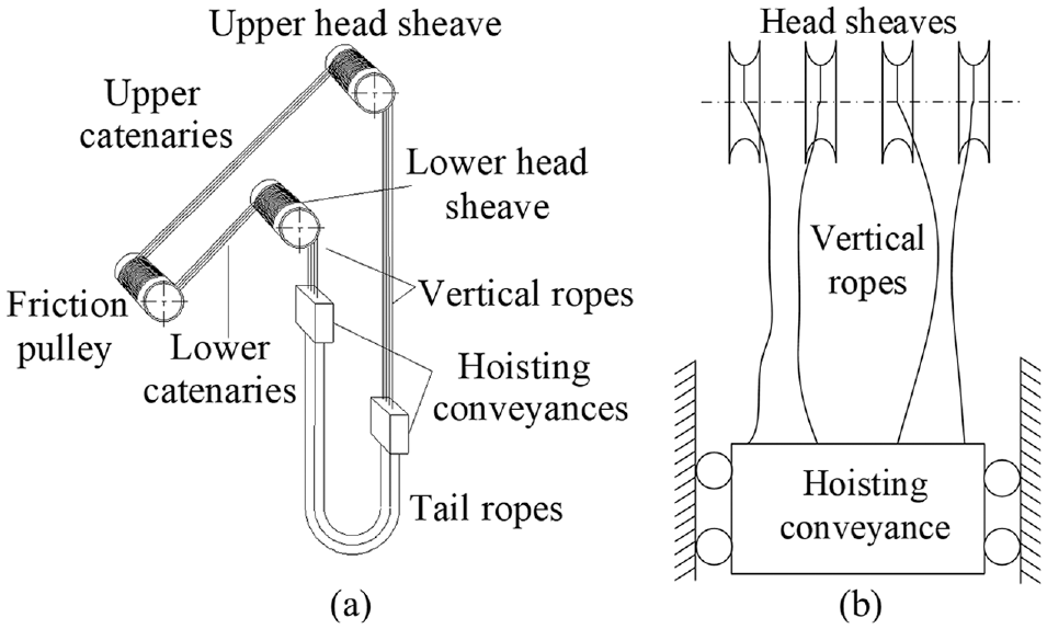
(a) A multi-rope friction mine hoist and (b) transverse vibration sketch of vertical ropes.
Hoisting rope is a typical flexible structure, which is a continuum of one-dimensional movement during operation of mine hoist. 4 Generally, under laboratory conditions, the acceleration, and velocimeter can be attached to hoisting vertical rope to measure its vibration responses, and they can only be used for a fixed point.5,6 However, for hoisting ropes in mine, installing sensors is difficult, and the measurement range is small as a result that the sensors cannot move round the head sheave; moreover, the torsion of sensor itself affect the measurement accuracy, so they are unsuitable and unreliable for the vibration measurement of hoisting ropes. Therefore, we need to consider adopting a non-contact and unmarked measurement method to obtain the vibration displacements of vertical ropes. However, there is no effective way that has been reported to measure the vibrations of moving vertical ropes so far.
For the vibration measurement of the linear structures possessing analogous properties with hoisting vertical ropes, the research of non-contact measurement techniques has made some achievements. The vibration responses on the stay cables for monitoring their health can be measured by microwave remote sensing technique,7,8 laser sensor, 9 GPS with an accelerometer, 10 and GPS with Beidou navigation satellite system (BDS). 11 Although the vibration measurements using microwave and laser sensors have very high accuracy, they are expensive for their single point and unidirectional measurement, and the sensors are difficult to be installed. GPS technology has a certain degree of accuracy, but it has a large error; in addition, the data are not easy to be collected and its economy is poor.
In recent years, machine vision-based measurement techniques are adopted increasingly,12,13 and they can perform multi-point vibration measurement of the flexible structures appears in a complete vision field.14,15 For instance, Ji and Chang 16 measured the tiny cable vibration displacement by using a proof-of-concept image-based technique. Park et al. 17 proposed a novel vision-based partitioning approach to obtain the relative displacements and rotational angles of the large flexible structure. Kim and Kim 18 and Kim et al. 19 estimated the vibration displacement of a stay cable by using the DIC methods to identify the position of the region of interest (ROI). Kim 20 proposed a multi-template matching algorithm to determine the center of the targets on the cable surface. Li et al. 21 studied a target center extraction formula based on grayscale image to observe the vibrations of stay cables. Shan et al. 22 measured the vibration response of stay cable by using center extraction method of a circular marker. Kohut et al. 23 calculated the vibration displacements of some feature points in the transmission line cable based on a DIP method. Feng and Feng 24 used a vision-based sensor and the robust orientation code matching (OCM) algorithm to measure the vibration displacement of a cable. Yan et al. 25 carried out the displacement measurement of the cables in a footbridge by target tracking algorithm. In previous work, we applied target tracking algorithm, 26 the digital graphics overlay method 27 and edge detection algorithm 28 to measure the transverse vibrations of mine hoisting ropes, but these approaches can only achieve positioning of single rope at integer pixel level, which is imprecise enough for multi-rope hoisting system.
The existing literature indicates that the main object of flexible structures vibration measurement is an unmovable cable. Previous researchers have not considered the issue that multiple cables in a vision field can interfere the recognition of the measured cable and the problem that the change of target image features may lead to the failure of tracking target. The differences between hoisting vertical ropes and the cable are that the upper ends of hoisting vertical ropes are unfixed and the spatial position of a certain point in moving ropes is changed. Therefore, unlike these cables, it is not feasible to paste any markers in vertical rope to separate the test point from other parts, and moving vertical rope make the measured target be variable slowly in an image sequence. Thus it is not only necessary to eliminate the interference of unmeasured parts on the test rope, but also it needs to recognize the change of target image features. All these problems are required to be solved for vibration measurement of hoisting vertical ropes.
In this work, for obtaining the accurate data for evaluating the dynamic characteristics of hoisting vertical rope, we proposed a non-contact vibration displacement measurement method without any markers based on the DIC and DIP algorithms. In this method, a reference line perpendicular to the vertical ropes is added in image to obtain an intersection point, which is the point of interest (POI) in vertical ropes for vibration measurement in space, so that the position of the measured point is fixed in a single direction and the common DIC method can track the vertical rope that moves up and down. After that, using an adaptive template matching algorithm to solve the problem that the conventional template matching algorithm cannot track the target region on the moving hoisting rope whose surface characteristics are changing. Finally, a simple displacement threshold method can extract the current measured vertical rope from multiple identical vertical ropes in the camera visual field, avoiding the failure of locating the current measured point, and making it possible that locating the multiple identical targets simultaneously.
The rest parts of this paper are described as follows. The next section introduces the vibration measurement principle of hoisting vertical rope and a new measurement method combining the DIP and DIC algorithms. Section “Case study” presents the measurement results of the transverse vibration displacements of three points on a vertical rope in an actual hoist. In “Experimental validation,” a laboratory test is performed to verify the proposed method. The last section gives the conclusion of this work.
Methodology
Measurement principle
The primary vibration of hoisting vertical rope is along the axis direction of head sheave, which is the transverse vibration mentioned above. The schematic of transverse vibration measurement principle for a single hoisting rope is given in Figure 2.

Schematic of the measurement principle.
Actually, a vertical rope is in the initial position at t = 0, and it moves round the head sheave in the vertical direction; and at t = ti, it is in the dynamic position. The offset distance between the dynamic position and the initial position is its vibration displacement. For determining the position of a measured point in an actual vertical rope, define a rope coordinate system with an origin o that is the tangent point of head sheaves and x-axis that is the central line of the vertical rope in initial position. The point M0 in vertical rope with a distance xm from origin o can be selected as a measured point. Thus a high-speed camera that is a non-contact sensing device can be placed at the position near the point M0 to capture images data. In the process of DIP, a reference line perpendicular to the vertical rope and passing through the measured point needs to be added, which can fix the measured position and the intersection point between the reference line and the vertical rope is a virtual marker in image.
As shown in Figure 2, the two intersection points are M0 and M i . Applying appropriate machine vision algorithm can determine their positions of in the video image sequence. It is assumed that the image coordinates of points M0 and M i can be determined as (x0, y0) and (xi, yi). Then, at t = ti, the transverse vibration displacement of the measured point can be calculated as follows:

where L(ti) is a transverse vibration displacement; λ is a scale factor with unit mm/pixel, which is used for translating the pixel distance to actual displacement; i = 1, 2, 3, …, N, and N is the frame number of video image sequence.
Image acquisition
Like the traditional sensor measurement technology, the high-speed camera is a kind of non-contact sensor for image data acquisition. In order to improve the measurement accuracy, an easy-to-install and high-speed camera with a CCD sensor and a portable lense is adopted, which is shown in Figure 3.
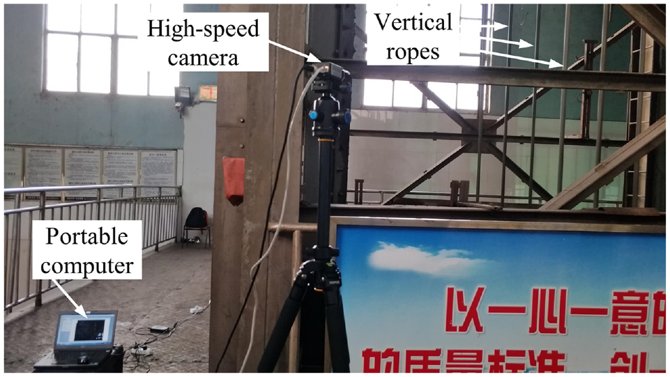
Image acquisition system in field.
The camera with a lens (16 mm) can capture the video images, which are digitalized at 768 × 1024 pixel resolution and each pixel is 8-bit data type, and its sample rate reaches 1000 fps. Moreover, the image acquisition system also includes a portable computer that is used to install image acquisition software and store the video images. During the process of image acquisition, it is usually possible to mount the camera directly to the tripod, which is necessary to be installed on solid ground. In the work, the vibration measurement of an actual hoisting vertical rope was executed at the auxiliary shaft of Yaoqiao Coal Mine attached to China National Coal Group.
Locating the vertical ropes
Figure 4(a) shows an original image that the surface characteristics of the adjacent part of a vertical rope can keep good consistency. Therefore, it is impossible to identify a measured point whose gray level has distinct difference from other parts of vertical ropes in an image directly. To this end, we added a reference line that is perpendicular to all vertical ropes in the original video images. Thus, their intersection area is regarded as a measured point for tracking the vertical rope. A reference line is obtained by changing the grayscale values of some confirmed pixels around the measured point in the original images. Generally, a pure white or black reference line that is obviously different from the image background is essential. So the grayscale values of these pixels identified can be set to 255 or 0, getting a pure white or black reference line.

(a) The first-frame original image and (b) the changed image with a black reference line.
In the case study that is the section 3 of this paper, we took the 3# vertical rope shown in Figure 4(b) as the research object to perform the transverse vibration displacement measurement of a vertical rope in service. The point M in the 3# vertical rope was selected as the measured point. Therefore, we added a black reference line that was through the measured point M and perpendicular to the vertical ropes in the original image by setting the grayscale values of the 10 pixel rows around the point M to 0. A changed image with a reference line is shown in Figure 4(b). Obviously, the point M is separated from the other parts of the 3# vertical rope, which makes the measured point be fixed on the reference line. In all images, the same reference line needs to be added in the same position.
In this paper, the research objects are vertical ropes, and the reference lines added in all images can be perpendicular to the linear ropes as long as they are horizontal. For non-vertical linear structures in images, it is necessary to determine their perpendicular lines in the image coordinate system firstly. Then a reference line is added by setting the grayscale values of the pixel points belong to several adjacent perpendicular lines around the measured point to 0 or 255.
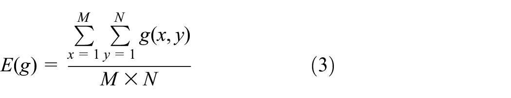
In the processed image, the image features of hoisting ropes in measured positions are extended to the two-dimensional state, which makes a common DIC algorithm can track the measured points on the rope. In this way, a DIC algorithm based on DIP is established. For indicating the correctness of this improved unmarked matching way independently, we chose the reliable normalized cross-correlation (NCC) algorithm 29 for locating the measured point in every image. An appropriate template can be used to search the best-matching region by calculating the NCC coefficients between the matching template and the different sub-regions in an image being searched pixel by pixel. Generally, NCC coefficients C(u, v) can be defined as:

where g(x, y) is a matching template whose size is M × N pixels; f denotes a sub-region of an image being searched with the pixel size of MM × NN, and MM > M as well as NN > N; (u, v) represents the pixel location of the sub-region being matched and u∈ [1, MM – M] as well as v∈[1, NN – N]; E(g) and E(f) are the average grayscale values of the matching template g and the sub-region f, respectively. E(g) and E (f) can be computed as follows:

Although the surface properties of adjacent parts on the hoisting rope are consistent, it can reach more than 1000 meters, and its surface of those parts close to the mine bottom will be polluted. Consequently, the surface characteristics of hoisting vertical rope are not identical in all parts, and the tracked object in the measured position is changing with the vertical rope moves up and down. Figure 5 shows two different sub-images from two images acquired at different times. The average grayscale values of the rope regions in the two images are 25 and 70, respectively, and they are significantly different from each other. In addition, the harsh environment and complex hoisting system accessories such as headframe and other auxiliary devices around hoisting ropes lead to the image background are complicated, which interferes the extraction of hoisting vertical ropes. All these facts make that the grayscale information of some pixel regions including vertical rope and its surroundings in different images are not similar. Therefore, using a single template to track the moving vertical rope can reduce the object recognition accuracy for the reason that the changeless template cannot track the object whose surface characteristics and surroundings are changing.

Vertical ropes in two different sub-images.
To tackle this problem, target tracking algorithms such as mean shift 26 normally use the best matched region in the current image as a template to track the target in the next image. However, the way makes that the template is updated too frequently, and it is easy to accumulate matching errors, causing the drift of the matching template and the failure of target tracking. For this, we proposed an adaptive template updating (ATU) algorithm based on current matching results, which can suppress the accumulated errors from frequent template updating effectively. The updated template T(i, j, t + 1) can be obtained by

where T(i, j, t) is the current template; O(i, j, t) is the best-matching region in current image; α is the maximum correlation coefficient from the current matching results.
The localization of a measured point at integer pixel level26–28 is not meet the desired accuracy of displacement recognition. For NCC coefficients C(u, v) and their corresponding coordinates (u, v), we utilized the three-dimensional fitting method to get their relationship, and a fitting result is shown in Figure 6.

The fitting result of NCC coefficients and their coordinates.
It can be seen from Figure 6 that all of the fitting curved surfaces around the peak positions are very similar to Gauss surface. Therefore, we developed a sub-pixel DIC algorithm by combining the Gauss surface fitting algorithm with the NCC algorithm. Thus, the sub-pixel coordinates corresponding to the extreme value of a two-dimensional Gauss function that expresses the fitting Gauss surface can represent the position of the measured point and be identified easily.
Extracting the measured vertical rope
For vibrations measurement of hoisting vertical ropes, a matching template with suitable size is the ROI in the first frame image. Actually, it is necessary to calculate the NCC coefficients pixel by pixel. However, if the pixel size of the image being searched is very large, the invalid computation load will also increase, which decreases the matching speed and makes the NCC algorithm be unsuitable for vibration monitoring. However, if the searching image is too small, the measured rope does not exist in it at some moments, making matching fail. In general, the searching image should be large as far as possible in the transverse direction, and it can be feasible to choose a sub-image including the two unmeasured ropes nearest the measured rope, ensuring that all possible positions of the measured point are in it.
Therefore, in every image, the rectangle region A shown in Figure 4(b) can be selected as the sub-image being searched, which includes the measured 3# rope, the unmeasured 2# and 4# ropes. An extracted region A is shown in Figure 7. In the region A of the first image, a semi-automatic template selection method can identify the matching template by clicking the position of measured point with the mouse according to a pre-set template size. In addition, the matching template selected is also shown in Figure 7.

A sub-image including the template.
However, during tracking the measured point M, it can locate to the point O or P on 2# or 4# rope in all probability, leading to the failure of vibration measurement. For solving the problem, we utilized a simple approach to optimize the matching results based on the fact that the distance between the two measured points in the two adjacent images is not too large as long as the sampling frequency of image data is large enough. Applying the approach needs to set a distance threshold to make the distance between the two measured points in two adjacent images is lower than this threshold, which ensures the matching point being measured is on the same vertical rope in every image.
Specifically, suppose the pixel coordinates of the measured point in the current image are (xi, yi), and its pixel coordinates obtained by the NCC algorithm in the next image are (xi+1, yi+1) with the maximal correlation coefficient; in addition, the distance threshold is set to T that is a possible maximum value of the distance D between the two measured points in two adjacent images, which can be calculated as:

If D < T, then (xi+1, yi+1) are the pixel coordinates of the measured point in the image being searched; Otherwise, it is necessary to search iteratively for the next maximum value of the correlation coefficient and determine the pixel position (xi+j, yi+j) of the matching point until D < T. Thus, (xi+j, yi+j) are the pixel coordinates of the measured point.
Case study
In this work, the transverse vibration displacement of a vertical rope belonging to a multi-rope friction hoist being in service was measured. As mentioned before, the point M shown in Figure 4(b) was the research object to measure the vibration of an actual hoisting vertical rope. In order to reduce the calculation load of using the NCC algorithm, a sub-image with the pixel size of 101 × 241, as shown in Figure 7, was regarded as the image being searched. In Figure 7, it has also shown the selected template with the size of 31 × 31 pixels. The point M in each frame of the video image sequence was tracked by using the improved NCC algorithm with ATU algorithm and setting a displacement threshold that was five pixels.
Using the improved DIC algorithm based on DIP, the sub-pixel coordinates of the point M were identified as (35.000 3, 111.995 2) in the first image. Similarly, the sub-pixel coordinates of the measured point in each image need to be determined, thus the vibration pixel displacement of hoisting vertical rope can be calculated. Subsequently, it is necessary to transform the pixel displacement to the actual displacement. In Figure 4(b), the width of a vertical rope was identified as 15 pixels by using edge detection algorithm, and the actual diameter of the vertical rope in the hoisting system is 40 mm. So the scale factor of the actual distance and its pixel distance can be calculated as 2.6667 mm/pixel.
The transverse vibration displacement of the point M on 3# vertical rope in the acceleration stage of the hoist was measured by using the proposed vision measurement method, and the transverse vibration displacement-time histories were recorded in Figure 8(a). Furthermore, the method reported in this paper can also carry out multi-ropes vibration measurement simultaneously. However, we selected the other two points on the same rope to illustrate the stability of the method. Therefore, the vibration displacements of another two points M1 and M2 in 3# vertical rope were also measured. It should be noted that the point M1 is in the region that the grayscale difference between vertical rope and image background is small, and the point M2 is in the region that the image background is diverse. The measurement results were recorded in Figure 8(b) and (c).

The displacement-time histories of the three measured points: (a) point M, (b) point M1, and (c) point M2.
Seen from Figure 8, there is no single mutation in all vibration displacements, making it clear that the measuring points can be tracked. Comparing the vibration displacement measurement results of the three points, it is easy to find that the three displacement-time histories are same fundamentally, only with a difference in amplitude. All of these situations indicate that the method reported in this paper is feasible to measure the vibrations of moving vertical ropes in various situations.
Experimental validation
Experimental setting
Owing to that the existing vibration measurement methods are not suitable to get the vibration displacement of the moving hoisting vertical rope directly, it is impossible to do a contrastive experiment to verify the proposed method in an actual mine hoist. Therefore, we designed a simulation experiment system under laboratory conditions, and all of the experimental setups are shown in Figure 9.

Simulation experiment system.
The two vertical ropes were parallel to each other, representing two adjacent hoisting vertical ropes in the actual multi-rope friction hoist. To perform contrastive experiment, a laser displacement sensor (LDS), which was at about 60 mm away from the vertical rope, was fixed to the magnetic stand through an iron sheet. The measurement accuracy of the LDS is 0.02 mm. A portable computer connected to the LDS by signal acquisition card was used to store sensor data. The high-speed camera with about 2 m away from the experimental ropes and the portable computer aforementioned were installed at the right place for images acquisition.
In order to simulate the transverse vibration of a vertical rope, we used the vibration force hammer to knock the appropriate position in the experimental vertical rope so that it could produce horizontal vibration with a certain largest displacement. In the vibration process of vertical rope, a LDS and the high-speed camera were utilized to collect vibration data simultaneously and store them in the computer for calculating the vibration displacement. An original image captured by the camera is shown in Figure 10. In the experiment, the vertical rope 1 is close to the LDS, which is the measured wire rope, and the adjacent vertical rope 2 is regarded as an interference rope.
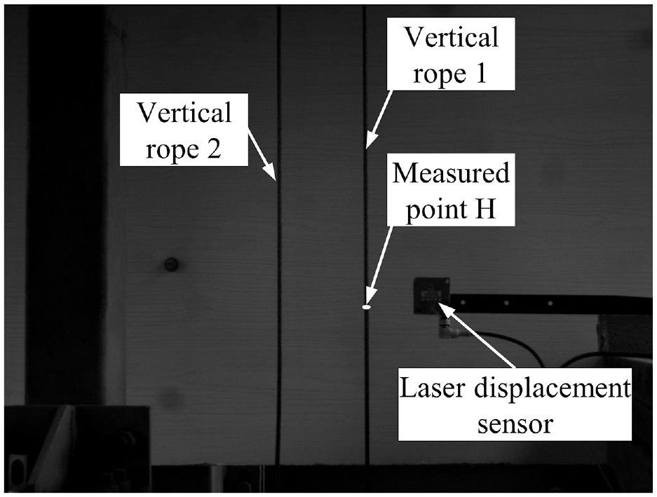
An original image including experimental vertical ropes.
Experimental results and discussion
In Figure 10, the point H on the vertical rope 1, which was the intersection of an experimental vertical rope and the laser beam produced by a LDS, was regarded as the measured point and the artificial transverse vibration of a vertical rope was measured. Figure 11 illustrates the vibration displacement-time histories of point H measured by the proposed vision measurement algorithm and the LDS. By comparing the two measurement results, obviously, the two displacement-time histories are very consistent in the degree and trend of vibration changes.
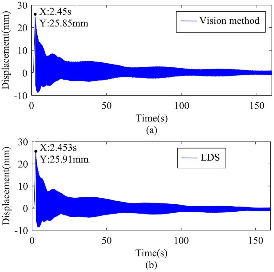
Displacement-time histories of the measured point H: (a) from the proposed vision measurement algorithm and (b) from the LDS.
In order to quantify the accuracy of stereovision measurement method, the normalized root mean squared error (NRMSE) is utilized to perform error analysis of measurement result, and the error value can be calculated by equation (7).

Where xi represents the ith data to be analyzed, and it is the displacement result measured by stereovision method; yi represents the ith data from the standard sensor. ymax and ymin are the maximum and minimum values of yi, respectively; n is the number of measurement data.
Through calculation from equation (7), the NRMSE of the measurement data obtained by using the proposed stereovision method is 0.2883%. It indicates that there is a very good agreement between the displacement records measured with the video system and with the LDS.
For implementing a comparative analysis of the two measurement results obtained from the proposed method and the LDS in the frequency domain, we used fast Fourier transform (FFT) to convert each vibration measurement result in the time domain into the frequency domain. The amplitude spectra of the vibration signals obtained by using the proposed vision method and the LDS are shown in Figure 12(a) and (b), respectively.

Amplitude spectra of the vibration signals: (a) from the proposed vision measurement algorithm and (b) from the LDS.
Figure 12(a) shows that the first-order vibration frequency of the measured point H in the experimental vertical rope are 4.57 Hz, and the second-order vibration frequency are 9.141 Hz obtained from vision measurement method, which are almost equivalent to those frequencies, which are 4.577 and 9.148 Hz shown in Figure 12(b), identified by the LDS. Through quantitative analysis, the deviations of the first-order and second-order vibration frequency are 0.15% and 0.07%, respectively.
The discrepancies between the measurement results based on the proposed measurement method and the LDS may be resulted from the low resolution and poor quality of the images. Noteworthy, like other machine vision measurement methods, it is possible to adopt higher resolution cameras for image acquisition to get a more precise measurement result. However, the displacement-time histories and amplitude spectra identified by the two methods are very consistent, which can verify the validity of the proposed machine vision vibration measurement method.
Conclusion
In this study, a non-contact, unmarked machine vision method is presented for transverse vibration displacement measurement of the hoisting vertical ropes in mine hoists. The application of DIP methods for adding a reference line makes the common DIC algorithm can track the points in moving vertical ropes, which possess consistent surface characteristics in some continuous parts, without any substantive markers. Then, the ATU and sub-pixel algorithm are introduced into the DIC algorithm to improve its robustness and accuracy for target tracking. A simple distance threshold method makes the proposed method can measure the vibration displacements of multiple ropes with different vibration states. The vibration displacements of three points in an actual hoisting vertical rope were measured and a verification experiment was carried out in a simulation experiment system, which verified the feasibility and accuracy of the reported approach.
The proposed machine vision measurement method is a promising tool to monitor the vibrations of moving hoisting vertical ropes in mine hoists, which can provide precise data support for reliability evaluation of hoist, researching on vibration mechanism and vibration abatement ways of hoisting vertical ropes. In addition, the resolution and sampling frequency of the camera may need to be raised to obtain more accurate measurement results. Moreover, this method not only makes it possible to execute transverse vibration displacement measurement of hoisting vertical ropes, but also it is very universal and can also be extended to applications in the vibration measurement of other flexible cable structures. However, the proposed method is time consuming, so real-time online measurement methods will be studied in future. In addition, multiple industrial high-speed cameras will be used to obtain the vibration displacement of hoisting ropes at the same time from multiple angles for improving the measurement accuracy and speed in our follow-up research.
Footnotes
Handling Editor: James Baldwin
Declaration of conflicting interests
The author(s) declared no potential conflicts of interest with respect to the research, authorship, and/or publication of this article.
Funding
The author(s) disclosed receipt of the following financial support for the research, authorship, and/or publication of this article: This work was supported by the National Natural Science Foundation of China (grant numbers 51675520 and 51975569).