
Abstract
Currently, there are no suitable means to measure the composite vibration response of mine hoisting rope. However, machine vision-based measurement technology is a potential way to solve this problem. Therefore, a non-contact and non-intrusive stereovision method is proposed to obtain the 2D vibration displacement of a moving hoisting rope. In this methodology, a novel 3D digital image correlation (DIC) method that combines digital image processing (DIP) algorithm with 2D-DIC algorithm is developed, and the method can simplify the procedure of rope target stereo matching in two synchronous image sequences. In order to confirm the correctness of the stereovision method, some free vibration responses of a rope are measured in a hoist experimental system. Test results demonstrate that the stereovision measurement technique can keep satisfactory consistency with the laser displacement sensor for vibration data identification. The method is verified to have high adaptability to different lighting conditions and be reasonable to measure the vibration parameters of dynamic mine hoisting rope.
Keywords
Introduction
Mine hoisting rope is the key component connecting the ground and downhole, and its dynamic characteristics can reflect the operational status of hoist.
1
Figure 1(a) shows the structure diagram of a friction mine hoist. Since the upper end of a vertical rope bypasses the head sheave and the other end is connected to the hoisting conveyance in the running hoist, the stiffness and mass of moving vertical ropes change constantly, which makes the hoisting rope prone to vibrate in space. The vibration diagrammatic sketch of hoisting ropes is shown in Figure 1(b). (a) Friction hoist in mine and (b) diagrammatic sketch of hoisting ropes vibration.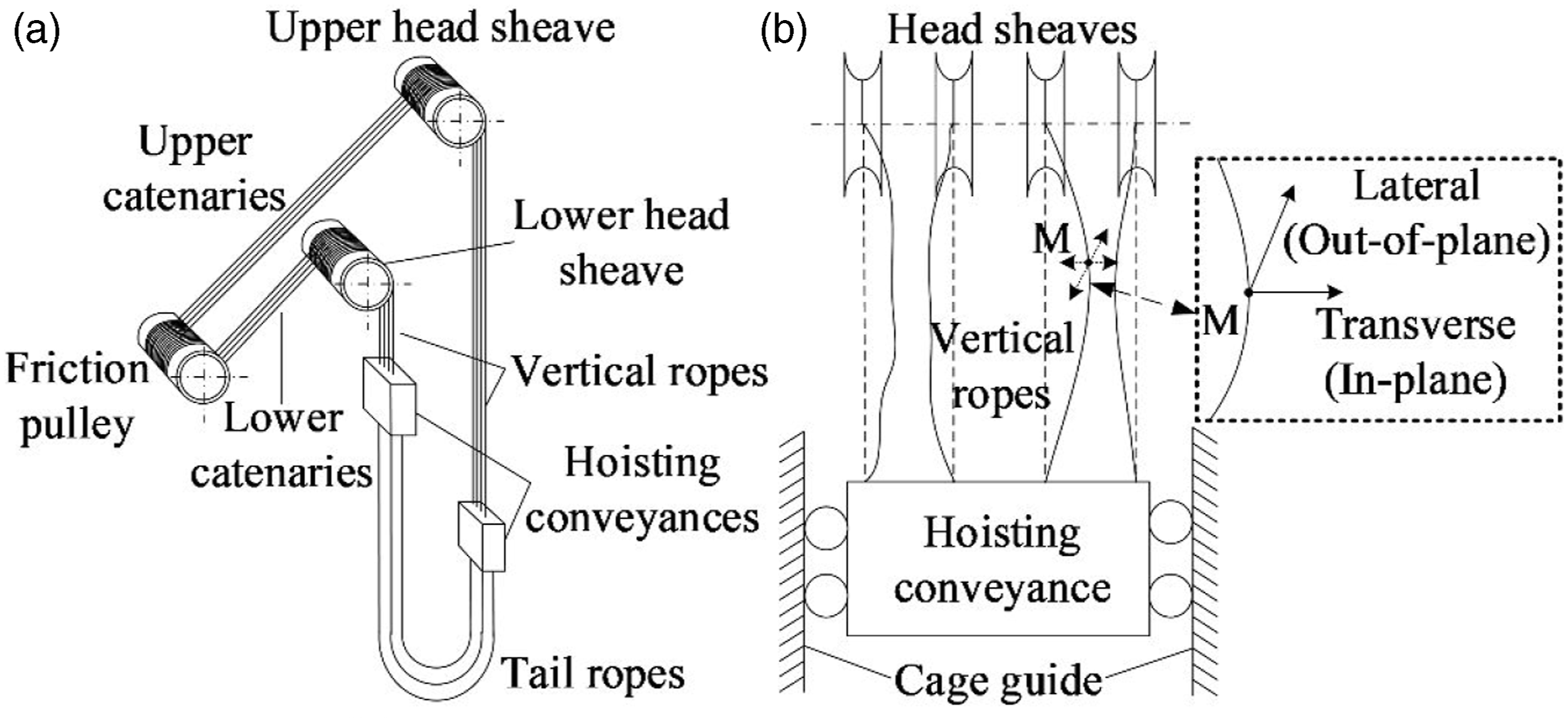
The free vibration of a hoisting rope, including the vibration displacements in the transverse (in-plane) direction and the perpendicular direction of transverse displacement that is called as the lateral (out-of-plane) direction, is composite. Generally, the transverse vibration is parallel to the axial direction of head sheave. Moreover, the faults of guiding devices and the axial swing of head sheaves lead to the composite vibrations of vertical ropes. Therefore, the vibration parameters of hoisting vertical ropes can provide accurate data for the structural health monitoring of a multi-rope hoist. If the vibration amplitudes of two adjacent vertical ropes are very large, it may make them collide with each other. This is an extremely dangerous state, which affects the safety of hoist and aggravates hoisting ropes, shortening their service life. 2 Therefore, in order to provide accurate data support for evaluating system operation status, it is necessary to research on the vibration monitoring methods of moving hoisting rope.
Generally, under laboratory conditions, the accelerometers can be installed on the moving hoisting vertical rope to measure its vibration response, and they can only be used for a fixed point 2,3 in a small measurement region for the reason that the sensor cannot move round the head sheave. However, it is difficult and risky to install sensors on the actual hoisting rope in mine, and the change of sensor installation direction caused by the torsion of hoisting rope will lead to measurement failure, so this way is unfeasible. Similarly, it is also inappropriate to fix markers with salient features and some known dimensions to the moving hoisting rope for vision methods. Therefore, it is necessary to use a non-contact and unlabeled way to get the vibration parameters of hoisting rope.
For the vibration measurement of flexible cable structure that is similar to hoisting rope, the non-contact sensors have been widely applied. The vibration responses of the stay cables are measured by microwave technique, 4,5 laser Doppler technology, 6 GPS with an accelerometer 7 and GPS with Beidou navigation satellite system (BDS). 8 Although the measurement accuracy of microwave and laser sensors is very high, they are expensive for their single point measurement in one direction, and it is inconvenient to install these sensors in the large-span space structures. In addition, there is a large error on GPS measurement technology, and its data acquisition is likely to be unfeasible due to signal masking in the first place and the data acquisition rate may not be suitable as well.
In recent years, the machine vision techniques by using DIP 9–11 and DIC methods 12–15 are increasingly applied to structural health monitoring, which includes vibration response measurement of stayed-cables. 16–20 In previous work, we applied a camera and DIP methods to the single transverse vibration measurement of mine hoisting rope. 21,22 All of these methods can perform multi-point dynamic displacement measurement of the flexible structures that appear in a complete vision field. 23–25 However, the current machine vision technologies utilize a camera to get the in-plane displacement of flexible cables and ignore the influence of out-of-plane vibration displacement, which will lead to inaccurate measurement results. In addition, these studies focus on the stay cables without axial movement, and there are few researches on the location recognition and vibration displacement measurement of 1D dynamic continuum, which is a structure that its size in one dimension is much larger than other sizes in the other two dimensions, and its movement are not constrained except for its two ends. The moving hoisting rope is a typical 1D dynamic continuum, and its image features are mainly in the axial direction.
In fact, 3D displacement measurement technologies of structures are also widely concerned by many researchers. 26–28 Helfrick et al. 29 developed a template correlation algorithm of surface speckle to identify the 3D deformation of a plane structure. Shan et al. 30 applied Zhang’s calibration method to two cameras calibration, and the 2D vibration displacements of circular marking point on a flexible cable are measured based on 3D deformation recognition algorithm in an experimental test. Diamond et al. 31 presented a new method based on optical flow technique to get the 3D vibration response of an electrodynamic shaker. Park et al. 32 identified the 3D vibration parameters of a confirmed sphere attached to T-bar based on the motion capture system (MCS) including three same cameras and circle center location algorithm. Chang et al. 33 utilized the close-range photogrammetric method to identify the 2D and 3D vibration displacement of substantial structure in a low-frequency section. Hunady et al. 34 described the relationship between affine transformation images to determine the positions of a target facet with stochastic speckle pattern in different images, and obtained its 3D vibration displacement through binocular stereovision technique. Lee et al. 35 carried out the star shaped target tracking through normalized cross-correlation (NCC) method, and the 3D vibration displacements of some different points in a plate structure were determined.
Most of the 3D vibration measurement techniques for various structures are applied with different markers on the structure surface, which greatly simplifies the implementing procedure of binocular stereovision technique. Therefore, it is feasible to determine the center position of the markers in two synchronous images separately for their 3D world coordinates reconstruction. The difference between the hoisting rope and these structures including stayed-cables in bridge is that the hoisting rope is moving along its axial direction, and thus the horizontal position of a certain point in moving rope is not constant. Therefore, it is impossible to predefine any substances on the hoisting rope.
In this paper, a stereovision technique without any substantive markers on the rope surface is proposed to obtain the 2D vibration response of a hoisting rope at a certain position in space, which includes transverse and lateral vibration, and it has been shown in Figure 1 and explained above. A novel 3D-DIC method is formed by combining the epipolar constraint equation and a DIP with 2D-DIC algorithm based on stereovision technique. A 2D-DIC method and the epipolar constraint equation are combined to form two matching reference lines, which can replace virtual polar lines, by using a DIP algorithm. Then the stereo matching of a same target can be carried out individually in two synchronous images. The validity of the new method was verified by comparing the vibration responses from laser displacement sensor (LDS) and the stereovision method in a free vibration measurement experiment of a hoisting rope.
Principle of stereovision-based hoisting rope vibration measurement
Figure 2 illustrates the complete procedure of stereovision vibration measurement method for moving hoisting rope, which allows simultaneous vibration identification of multiple points in the test area without any entity invading the rope. In this study, Zhang’s calibration method
36
is utilized to get the calibration parameters of binocular cameras and correct image distortion. The interesting space area selected for dynamic monitoring should also be identified prior to image acquisition, which needs to define a rope coordinate system. Moreover, the 2D vibration directions of a hoisting rope need to be specified in order to identify the optical axis direction of the camera, and it also ensures that the in-plane and out-of-plane vibration parameters represent the transverse and lateral vibrations, respectively, and makes it convenient to calculate the displacement. Then, two cameras are installed near the interesting area according to the vibration directions of rope. The detailed implementation process of the measurement method is clarified as follows. Flowchart of stereovision-based displacement measurement of hoisting rope.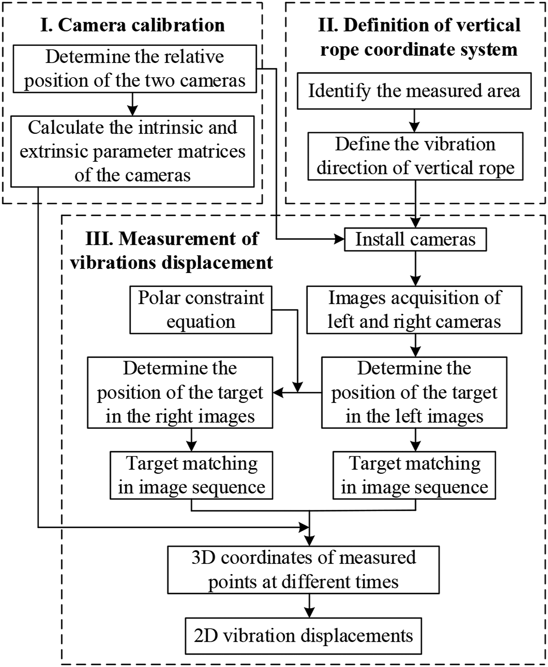
In the running hoist, the positions of all points on the hoisting rope are changing in the upright direction. Therefore, in order to obtain the 2D vibration displacement, it is necessary to fix the measuring point in a plane, which is determined by two intersecting lines in the transverse and lateral vibration directions of hoisting rope. The measurement schematic for a hoisting rope is given in Figure 3. Schematic diagram of displacement measurement for a rope.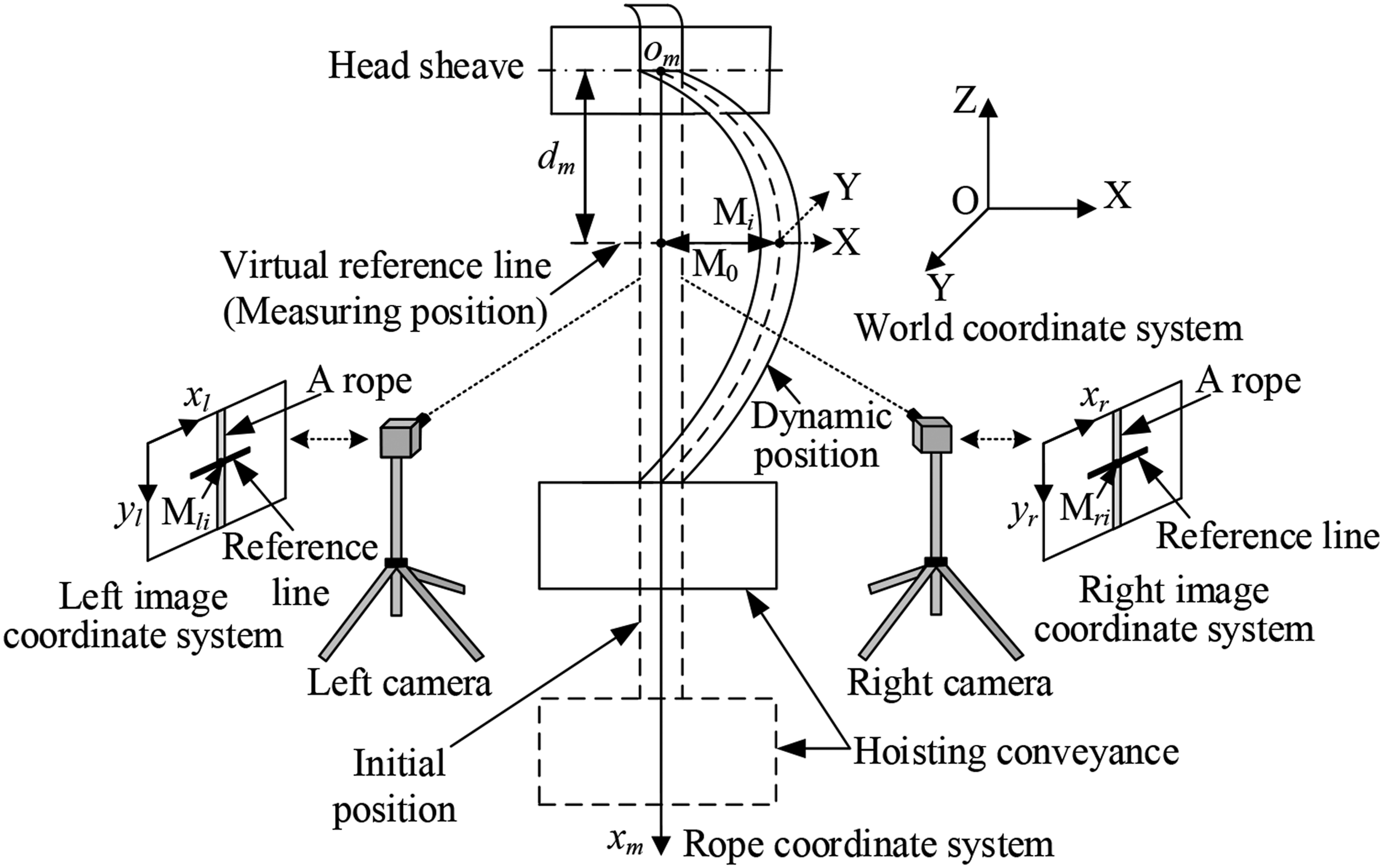
Actually, a hoisting rope moves round the head sheave in the upright direction, and it can vibrate from the initial position at t = 0 to the dynamic position at t = t i . It needs to define a rope coordinate system with an origin o m between head sheave and x m -axis that is the center line of the vertical rope in the initial position to determine the location of a measuring point on a vertical rope. An actual point M0 with a distance d m from origin o m can be regarded as a measuring point. M0 is the intersection of a virtual reference line and the rope in the initial position. Noticeably, the measuring point is not a fixed point on the rope, which represents some points passing through the measuring position.
A MCS with two high-speed cameras, that is, a set of non-contact sensing devices can be placed near the point M0 to capture images data. Obviously, a camera defines an image coordinate system, and a portion of the vertical rope filmed by the camera is a measurement area. Subsequently, the image feature of hoisting rope that is 1D dynamic continuum needs to be extended to the 2D state, which includes the features in the horizontal and vertical directions of the image, for distinguishing the current measuring point from other parts on the rope. Specifically, by means of DIP method, a reference line can be added to the measuring position, and the intersection region between the vertical rope and its perpendicular reference line is the position of a measuring point in the image. Significantly, the reference line should be in the whole image sequence.
Subsequently, an appropriate stereo matching algorithm can identify a matching reference line, and the two reference lines in a set of stereo images meet the epipolar constraint condition of stereovision imaging principle. Thus in the right image sequence, the spatial position that is consistent with the measuring point in the left image sequence is determined. According to the principle of machine vision, it is necessary to identify the image coordinates of the measuring point in successive images. If the position of a measuring point is determined, the target matching can be carried out independently to get its image coordinates (x
li
, y
li
) and (x
ri
, y
ri
) in the two image sequences, which can be transformed into the actual 3D world coordinates (X
i
, Y
i
, Z
i
) with the calibration parameters of two synchronous cameras. On the basis of the geometry constraint of binocular stereovision, if the rotation matrix
Finally, the 2D vibration displacement of a measuring point can be calculated by using the Euclidean distance formula between two points. 35
The theory of 3D-DIC combining 2D-DIC with Digital Image Processing
As for binocular stereovision technique, it is a key step to locate the measuring point in two image sequences. Considering the difference of a set of stereo images, image noises, perspective deformation, and the consistency of hoisting rope surface characteristics, there may be multiple points matching with the measuring point in synchronous images, leading to the matching distortion phenomenon. For this, a stereo matching method based on DIP and 2D-DIC is put forward. Generally, epipolar constraint, geometric similarity constraint, and unique constraint are used to supplement stereo matching. In the work, we chose epipolar constraint condition to support stereo matching of the measuring point in synchronous images.
DIP for target identification of hoisting rope
As for a hoisting rope, its surface characteristics of the adjacent positions on a certain part are identical. Therefore, it is impossible to identify a point of interest whose gray scale level has clear difference from other parts of a vertical rope directly. Thus during stereo matching of the measuring point, it can match other points that are above or below the current measuring point. Similarly, this kind of situation may appear for the target matching in a single image sequence. All of these phenomena will reduce the measurement accuracy and even cause measurement failure. To this end, an actual reference line mentioned above is necessary to be built in the original image sequence. Thus, the intersection area is regarded as a virtual marker that is clearly different from other parts on the same hoisting rope for conducting rope tracking.
In fact, a reference line can be obtained by simple gray scale transformation. Namely, the gray scale values of some definite rows around the measuring point selected in the original image need to be changed. Generally, a pure white or black reference line that is obviously different from the image background is essential. So the gray scale values of these known rows can be set to 255 or 0. Moreover, the gray value of the reference line is necessary to be different from the gray value of image background, which is easy to implement. As for the common DIC algorithm, as long as the target and image background are obviously different, the gray value has no effect on the positioning result.
In this work, the research object is vertical rope, and it is perpendicular to the linear rope as long as the reference line is horizontal. For non-vertical linear structures such as hoisting catenaries, it is necessary to identify their perpendicular lines first. Then a reference line is added by setting the gray scale values of the pixel points belonging to several adjacent perpendicular lines around the measuring point to 255 or 0.
Constraints of stereo matching
After determining a measuring point in an image sequence, it needs to carry out stereo matching of the point in another image sequence. For the epipolar constraint condition, the calibration parameters of two cameras are used to establish the epipolar constraint equation. As shown in Figure 4, the point P
l
and P
r
are on the left and right camera imaging planes, respectively, and they are defined as the projection points of an actual point P in space. Epipolar constraint model of binocular stereovision.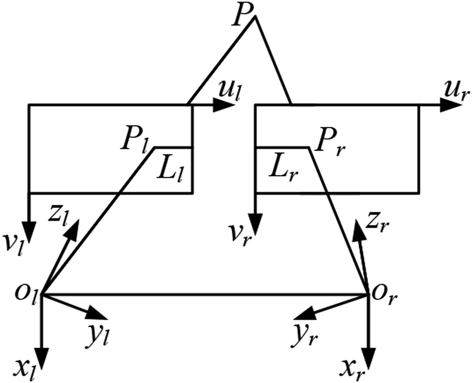
Obviously, O l and O r represent the optical centers of the two stereo cameras. The line connecting the two optical centers is called as baseline; the plane passing through the baseline is polar plane, and the image plane and the polar plane intersect to form an epipolar line. The intersecting lines between the polar plane and the two image planes are L l and L r , respectively, and the two lines are related to each other; that is, the projection points P l and P r of an actual point P in the left and right images are on L l and L r , respectively, which is the epipolar constraint condition. On the basis of general imaging principle, the epipolar constraint equation is derived as follows.
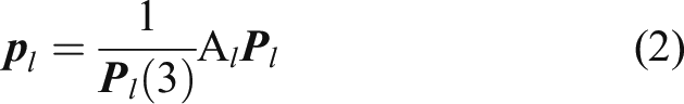
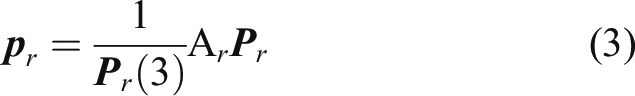
It is assumed that the two intrinsic parameter matrices of the two calibrated cameras are A
l
and A
r
, respectively; the rotation matrix and translation vector between the two cameras are R and
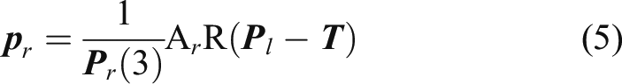
According to the position relationship of the two cameras, equation (4) can be obtained

Combine equations (4) with (3) to get (5)
Suppose

Evidently, the vectors


Suppose that the antisymmetric matrix of the translation vector

Therefore, the equation (9) can be written as equation (10)

Substituting equation (10) into equation (8) gives
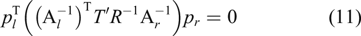
Equation (11) is the epipolar constraint equation, and suppose that

Evidently, F is a matrix with three rows and three columns, which is usually called the fundamental matrix of binocular stereovision. In this way, the simplified form of the epipolar constraint equation can be formulated as equation (13)

Consequently, provided that the homogeneous coordinate vector
Stereo matching of hoisting rope target
Supposing that the measuring point on a hoisting rope is fixed to the center line of the added reference line area in the left image sequence, then a line perpendicular to the hoisting rope can be obtained in the right image sequence. The two matching actual reference lines can be used to show and replace the virtual epipolar lines in all stereo images.
Specifically, in the initial frame of left original image sequence, arbitrary two points on the rope are selected along the radial direction of the vertical rope. Generally, the two points should be on the known center line of the overlapped part between the reference line and the vertical rope, which can determine two parallel lines in the first frame of right image sequence according to equation (13). In the study, a reliable 2D-DIC method that is the NCC algorithm
16,17,24,35
is utilized to carry out target matching in order to verify the correctness of this stereo matching way independently, and the centers of the two rectangle templates without reference line are the two points selected above. The correlation coefficients between the standard target image and the sub-images to be matched are calculated and compared pixel by pixel based on the image gray features. In general, the NCC coefficients C(u, v) can be defined as equation (14)
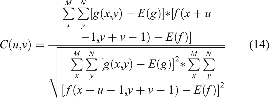
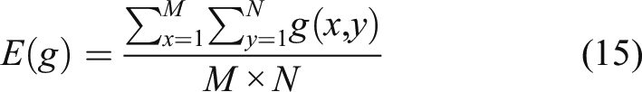
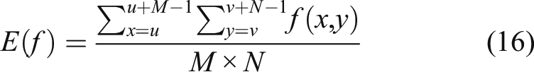
In this way, along the direction of the two parallel lines having been identified, two regions that are most similar to the two templates will be obtained, respectively, and their center points are the stereo matching points in the right image that are same with the two selected points in the synchronous image, respectively. The two center points define a straight line in the right image. In practical application, multiple points can be selected for linear fitting to obtain the more accurate matching line. The line can be regarded as the center line, and the same reference line that is matched with the added reference line in the left image sequence is constructed. So the intersecting region of the hoisting rope and the matching line can also be regarded as the virtual marker for conducting rope tracking in the right image sequence.
Depending on the unique constraint condition, in the right image acquired at a certain time, there is a unique point matching with the measuring point in the synchronous left image. Obviously, the virtual cruciform marker formed by the hoisting rope and reference line is at a unique location in each image. In this stereo matching method, two actual matching reference lines have met the epipolar constraint condition. Therefore, for the subsequent target matching, it only needs to match the target separately in the two image sequences for identifying the positions of these measuring points without calculating all epipolar equations and identifying all epipolar lines for independent stereo matching of the synchronous images at different times. Moreover, the template can be selected in the initial image of the left image sequence in order to avoid the inconsistency of template selection and simplify the target matching, and the template is applied to target matching in all images.
In target matching, we still employed the NCC algorithm with robust stability to environmental changes to track the measuring point in every image, and the location result is at integer pixel level. However, the measurement accuracy of displacement at integer pixel level is not enough. In order to determine the relationship between the NCC coefficients C(u, v) and their corresponding coordinates (u, v) for intersection target matching, the three-dimensional fitting method was used to get their relationship. A fitting result is presented in Figure 5, which shows that the fitting result around the peak position is very similar to Gauss surface. Therefore, we developed a sub-pixel template matching algorithm by combining the Gauss surface fitting algorithm with the NCC algorithm. The normalized cross-correlation coefficients and coordinates of intersecting target.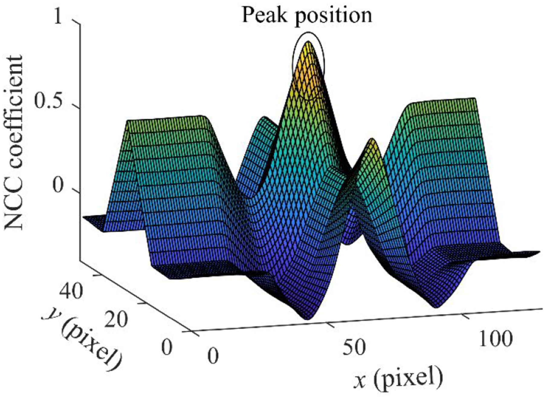
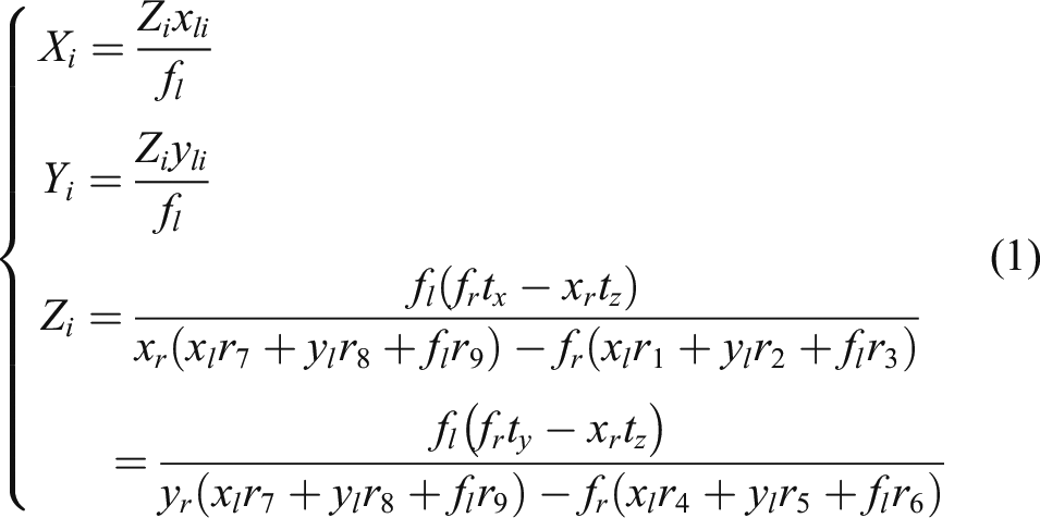
Thus, the proposed 3D-DIC algorithm can identify the sub-pixel image coordinates (x li , y li ) and (x ri , y ri ) of a measuring point in the two image sequences accurately. Based on the parallax principle of a measuring point in two simultaneous imaging planes, these image coordinates can identify the 3D world coordinates of the measuring point by equation (1), and they are utilized to obtain the 2D vibration displacement of hoisting rope.
Experimental validation
Experimental setting
Considering that the existing contact and non-contact sensors are not suitable to obtain the 2D vibration response of hoisting rope, a direct contrastive experiment for verifying the reportorial method cannot be performed in an actual mine hoist. For this reason, an experimental system under laboratory conditions was designed so that the two kinds of measurement methods including a standard LDS and the stereovision method could measure the free vibration of a hoisting rope synchronously. Figure 6 shows the schematic diagram of comparative experiment, and two cameras and two LDSs are used to collect the vibration data of hoisting rope. Experimental schematic diagram.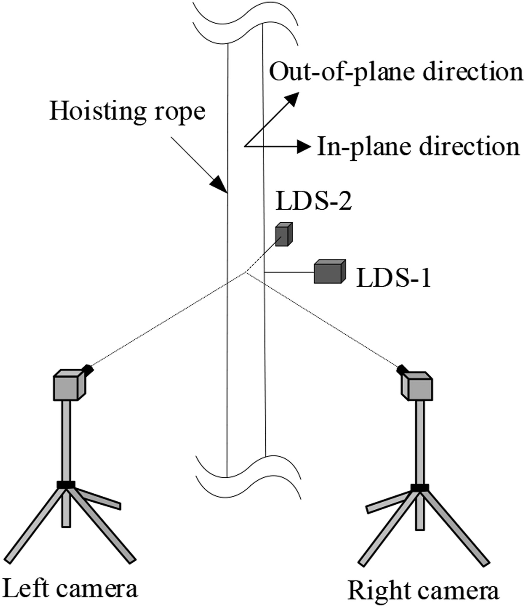
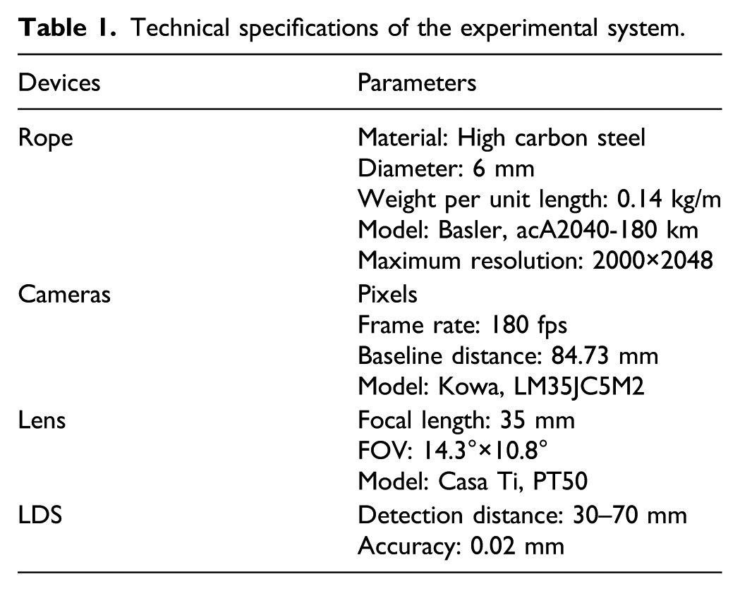
As shown in Figure 7, all of the experimental setups including sensor data acquisition system and image acquisition system are presented. The experimental hoisting rope belongs to a standard mine hoisting experimental system with a height of 13 m. The image acquisition system consists of two cameras, two portable lenses with fixed focal length, synchronous controller, image acquisition cards, an industrial computer, and control software. Some parameters of these devices are provided in Table 1
Experimental system. Technical specifications of the experimental system.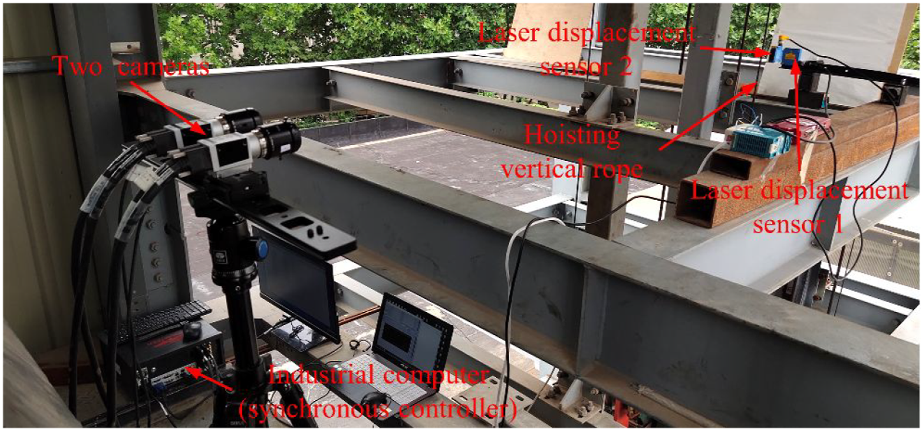
As for the two cameras, the 180 fps is their maximum frame rate corresponding to the maximum resolution. The resolution and frame rate of the two cameras are adjustable. With the decrease of resolution, the frame rate will increase appropriately. In order to ensure that the two cameras can track the moving target at the same time, a kind of binocular camera synchronization controller was chosen, and the synchronization control error for acquiring each pair of images is within .0001 s. The two cameras should be parallelly mounted on a tripod that is on solid ground, same as camera calibration. In addition, two laser displacement sensors are used to measure the rope vibration responses in transverse and lateral directions for performing contrastive analysis. Thus a contrastive experiment that could prove the correctness of the proposed stereovision vibration measurement method was carried out.
Contrastive experiment and results analysis
In order to indicate the measurement accuracy of the stereovision method, two free vibration tests were performed in the experimental hoist. In these tests, the two cameras were installed at the position with a distance of 1.5 m from the rope, which was close to the center of field-of-view. The two sensors were about 65 mm away from the vertical rope.
In the experiment, vibration responses of hoisting rope in the case that the hoisting conveyance was at rest were measured. A random transient excitation was given by knocking the experimental vertical rope along the appropriate directions so that it could produce random free vibration with a certain largest displacement in transverse and lateral directions, respectively. In this set of experiments, the artificial transverse (in-plane) vibration response of a vertical rope was primarily measured. The two kinds of data acquisition systems including laser displacement sensor-1 (LDS-1) and the two cameras were used to collect the vibration data. In order to get the vibration displacement of hoisting rope, all the captured images are input into MATLAB for image data processing and performing the stereovision method.
A measuring point H for the LDS-1 on the experimental vertical rope was also selected as the measuring point for the stereovision method. In the original left image sequence, a black reference line that was through the measuring point H and perpendicular to the vertical rope was added by setting the gray scale values of the 10 pixel rows around the point H to 0. Then, a same perpendicular reference line was constructed in the original right successive images by using the stereo matching algorithm introduced above. The result of adding a reference line to the original image is shown in Figures 8(a) and (b), and the laser displacement sensor-2 (LDS-2) is removed temporarily. For the sake of reducing the calculation load, the sub-image with the pixel size of 101×241, as shown in Figure 9, was regarded as the region of interest (ROI) being searched. Furthermore, Figure 9 also shows the selected template with 41×41 pixels, which has been different from the other parts of the experimental vertical rope. (a) A processed left image with an artificial black reference line and (b) a processed right image with a matching black reference line. A sub-image including the template.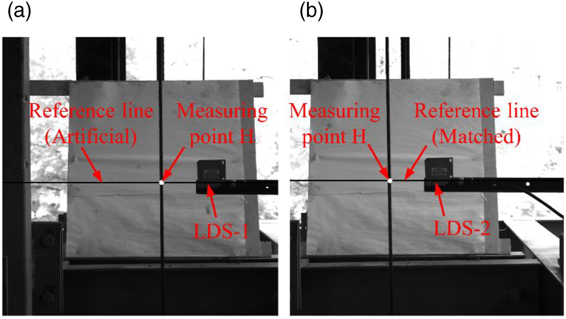
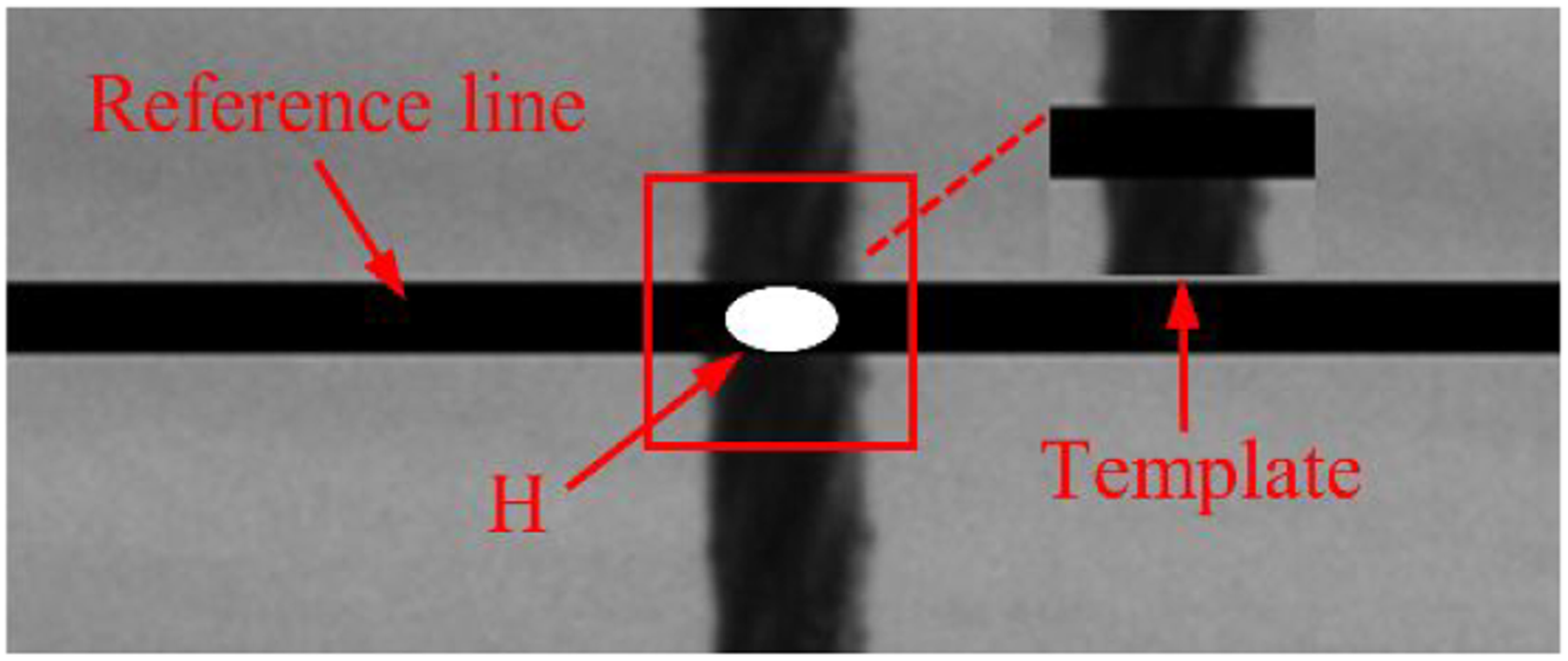
Figure 10 illustrates the vibration displacement measurement results of point H obtained by LDS-1 and the stereovision method based on 3D-DIC proposed in this paper. It is found that the two measurement results match quite well and are very consistent with a tiny difference. Moreover, the maximum and minimum of vibration displacement are 7.767 mm and −7.829 mm identified by the LDS-1, and they are almost the same as the maximum and minimum displacements that are 7.835 mm and −7.74 mm measured by the method proposed in this work. The artificial transverse vibration (in-plane) displacement of the point H.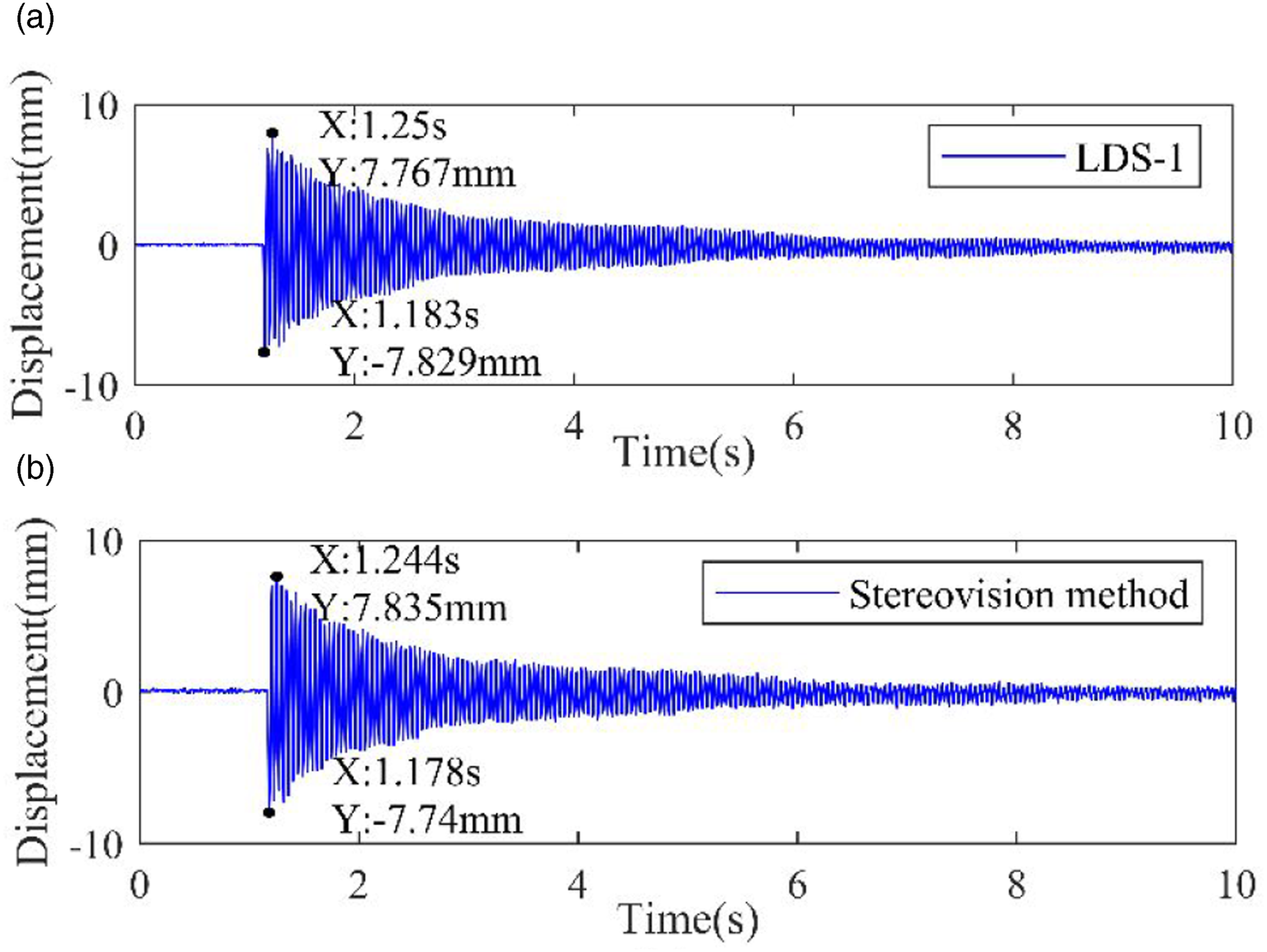
For the sake of quantifying the precision of stereovision measurement method, the normalized root mean squared error (NRMSE) is utilized to calculate the error of measurement result, and the error value can be calculated by equation (17)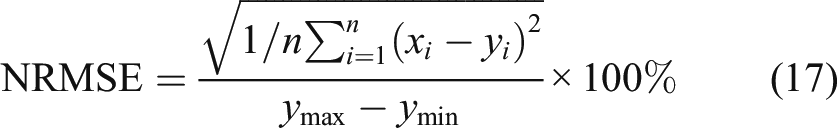
Through calculation with equation (17), the NRMSE of the measurement data obtained by using the proposed vision method is .3697%. It indicates that there is a very good agreement between the displacement records obtained by the vision system and the LDS, and the stereovision measurement method can obtain displacement measurement results with the same accuracy as LDS.
Then, fast Fourier transform (FFT) was applied to the measurement result transformation from time domain to frequency domain for implementing a frequency analysis of the two measurement results. Figure 11 demonstrates the transverse vibration amplitude spectra obtained by the two data acquisition systems. The first and second damped natural frequencies of point H in the experimental vertical rope are 23.0726 Hz and 46.1452 Hz identified by the stereovision method, and they are almost identical to those results measured by the LDS-1. Through quantitative analysis, the two test deviations of the first and second damped natural frequencies are all about .005%. The transverse vibration results in frequency domain: (a) from laser displacement sensor-1 and (b) from stereovision method.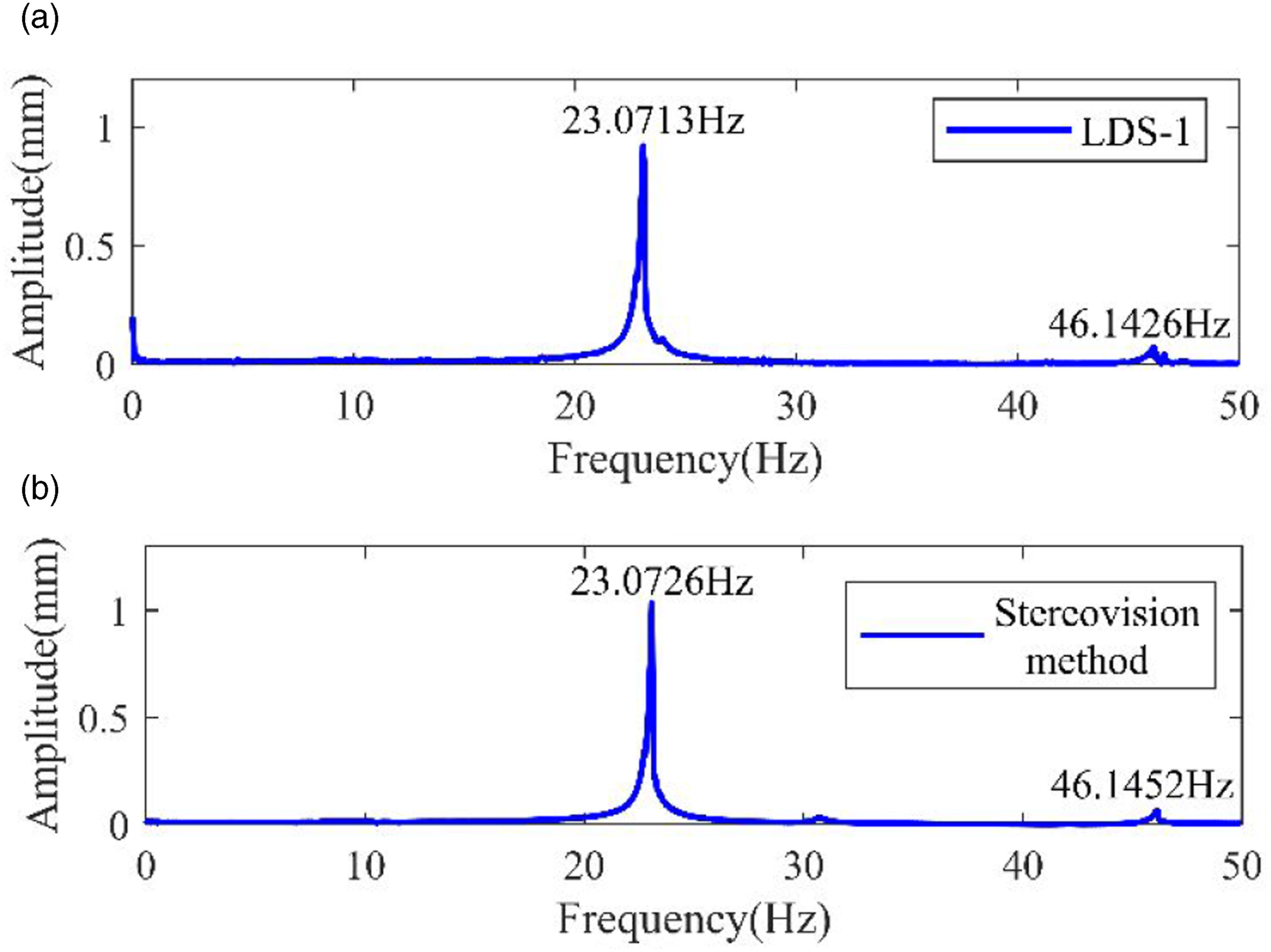
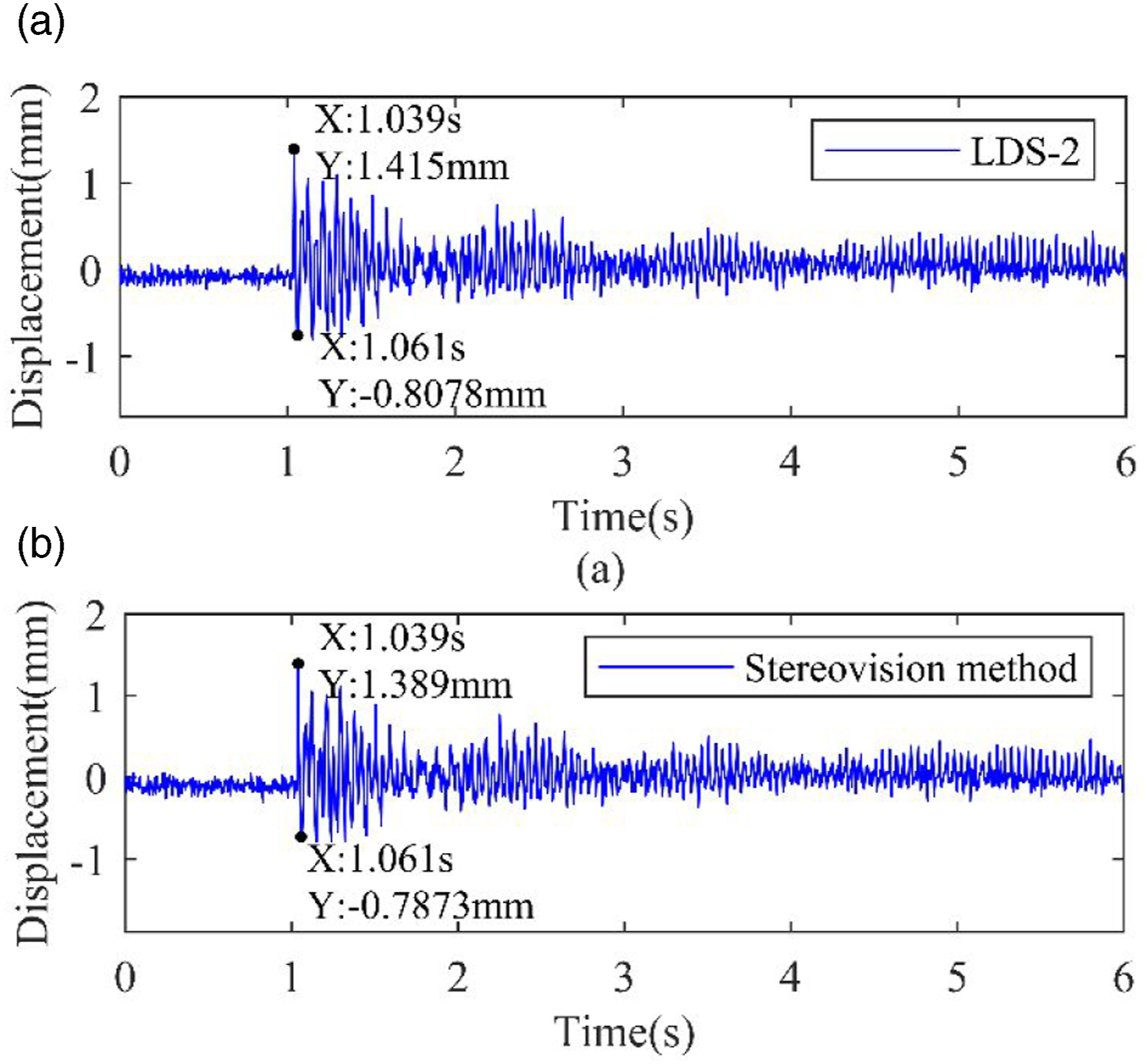
Next, another hammer impact experiment was conducted. In this test, the vertical rope could vibrate only in the lateral direction (out-of-plane). The displacement-time histories identified by the LDS-2 and the stereovision method were recorded in Figure 12. Comparing the measurement results from the two methods, and they are almost identical on the degree and trend of vibration change with a small difference in amplitude, which is mainly due to the inconsistency of two measuring points for the two measurement methods. The reason for this is that the LDS-2, as shown in Figure 13, has become the image background of vertical rope near the point H, which makes the gray features of vertical rope be the same with the background, and the parts of vertical rope cannot be tracked accurately. In this experiment, the point H1 for the stereovision method is about 15 cm away from the point H for the LDS-2. The artificial lateral (out-of-plane) displacement results: (a) point H and (b) point H1. The positions of measuring point H and H1.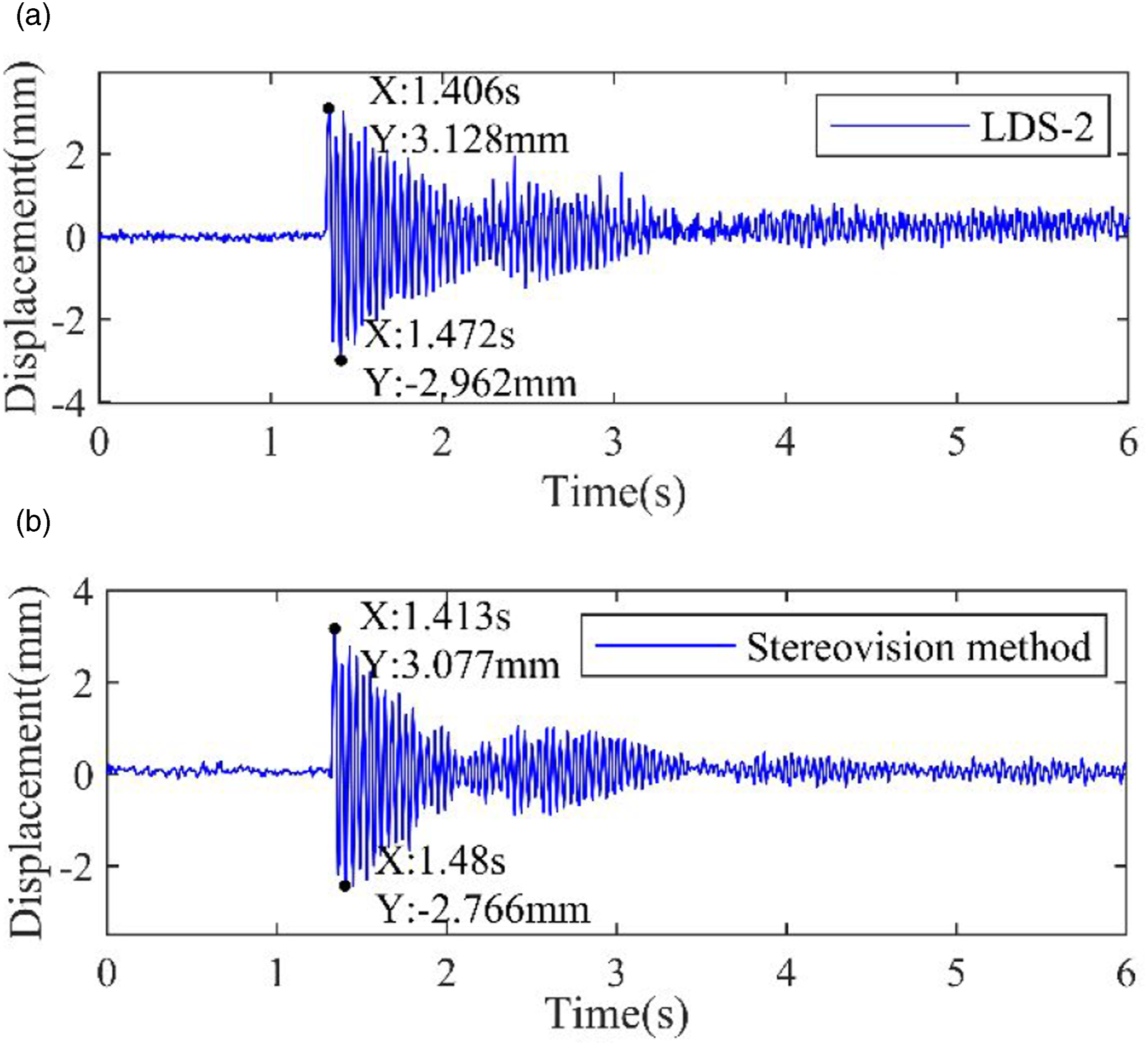
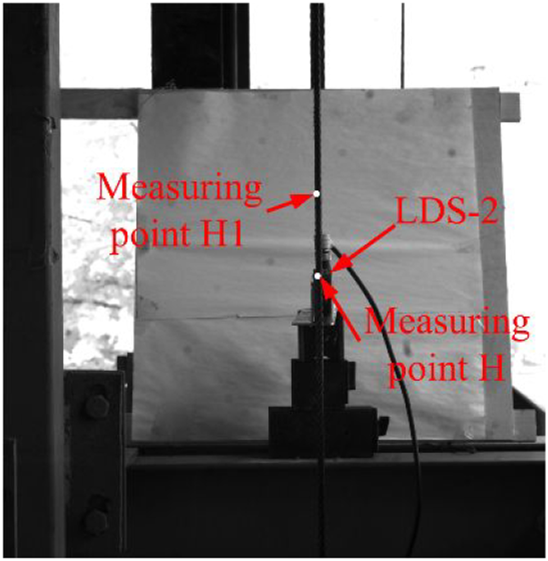
Figure 14 shows the lateral vibration amplitude spectra obtained by the LDS-2 and the stereovision method. The two first damped natural frequencies of out-of-plane vibration measured by these two ways are 24.17 Hz, and the two second damped natural frequencies are approximately 46.93 Hz. Obviously, the identified first two orders vibration frequencies are almost identical. Quantitative analysis reveals that the deviation of its second-order vibration frequency is about .021%. All these measurement results indicate that the vibration response of hoisting rope identified by the new vibration parameter measurement method is in reasonable consistency with them measured by a standard LDS. The lateral vibration results in frequency domain: (a) from laser displacement sensor-2 and (b) from stereovision method.
Effect of lighting condition
Considering that the experiment system is built in the outdoor environment, the vibration measurement experiment for studying the effect of light condition on the accuracy of the proposed method is carried out in three periods of a day, which correspond to different lighting conditions. For convenience, the three different lighting conditions are defined as lighting 1, lighting 2, and lighting 3, respectively.
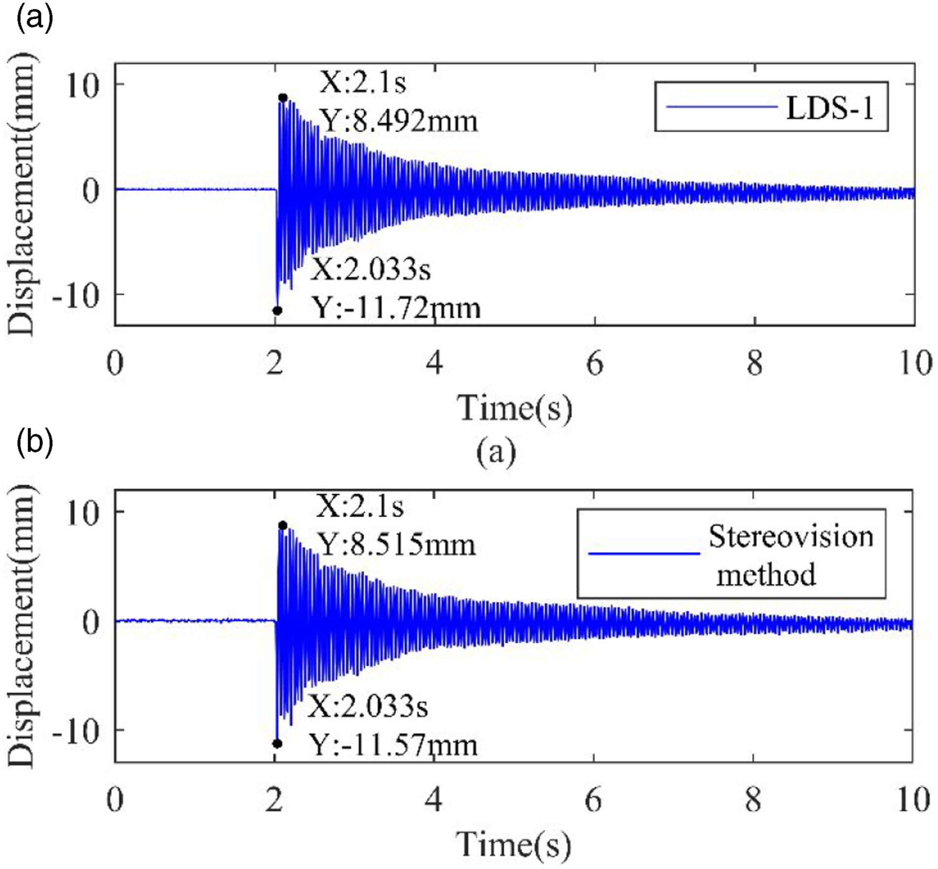
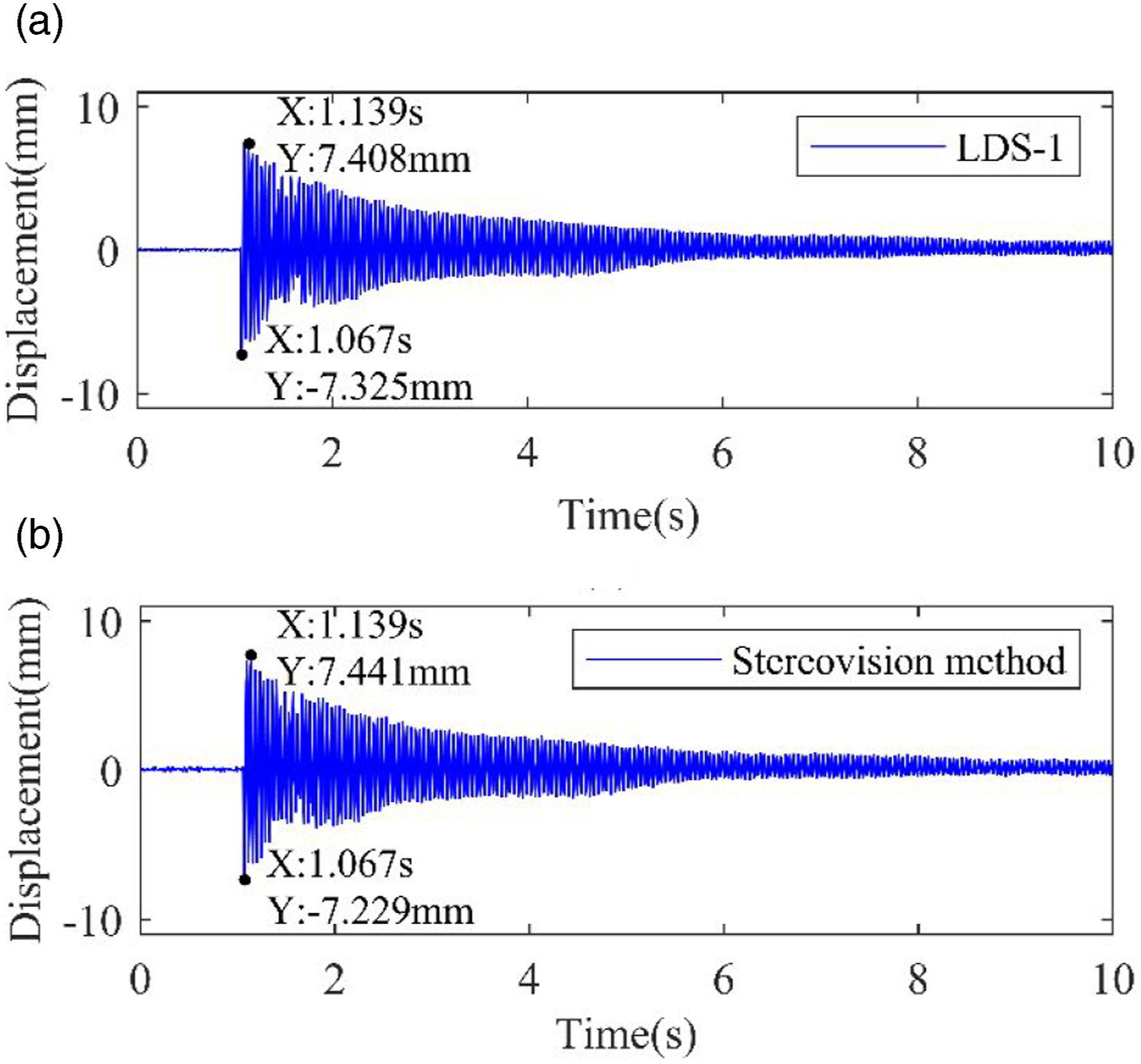
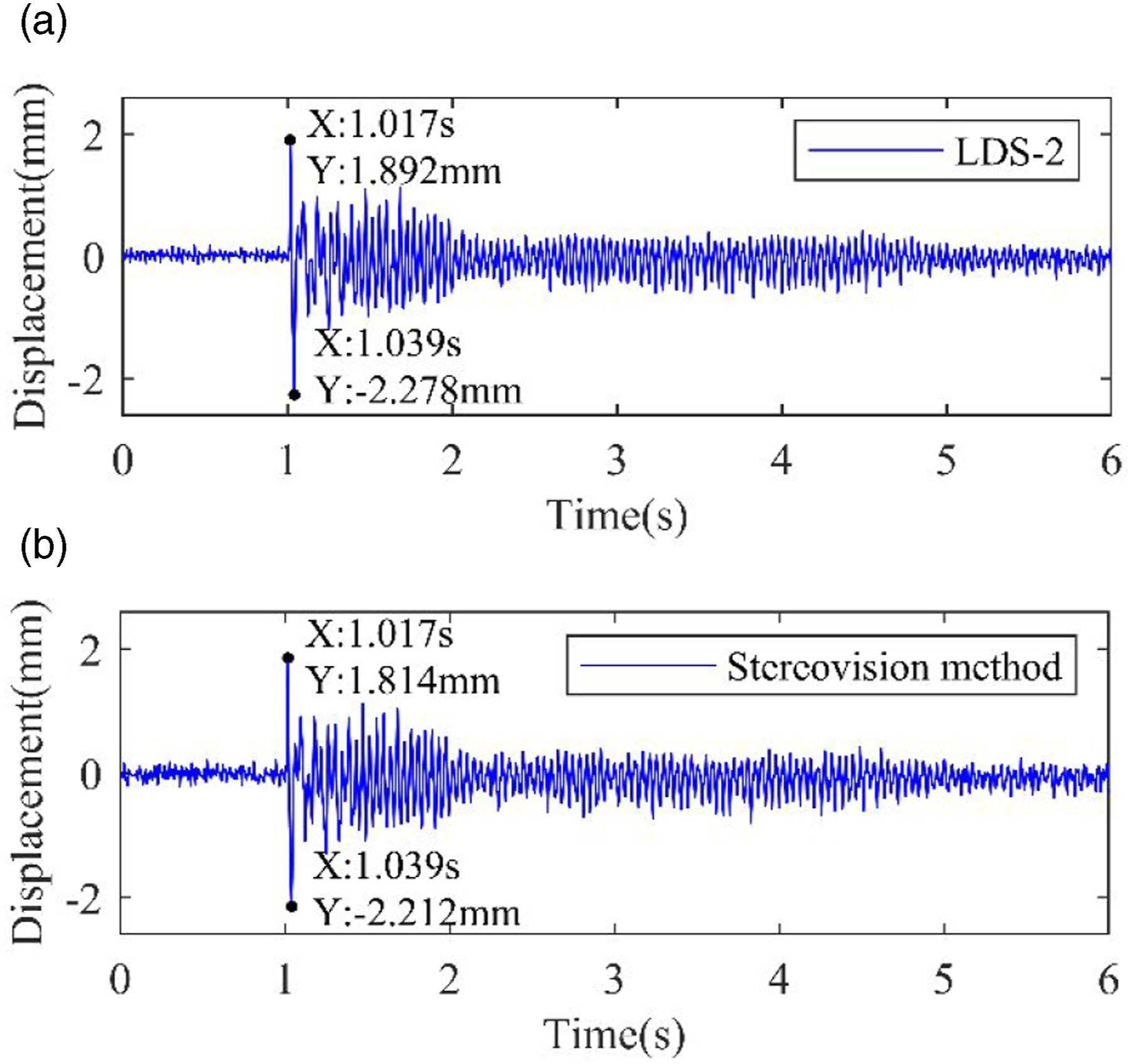
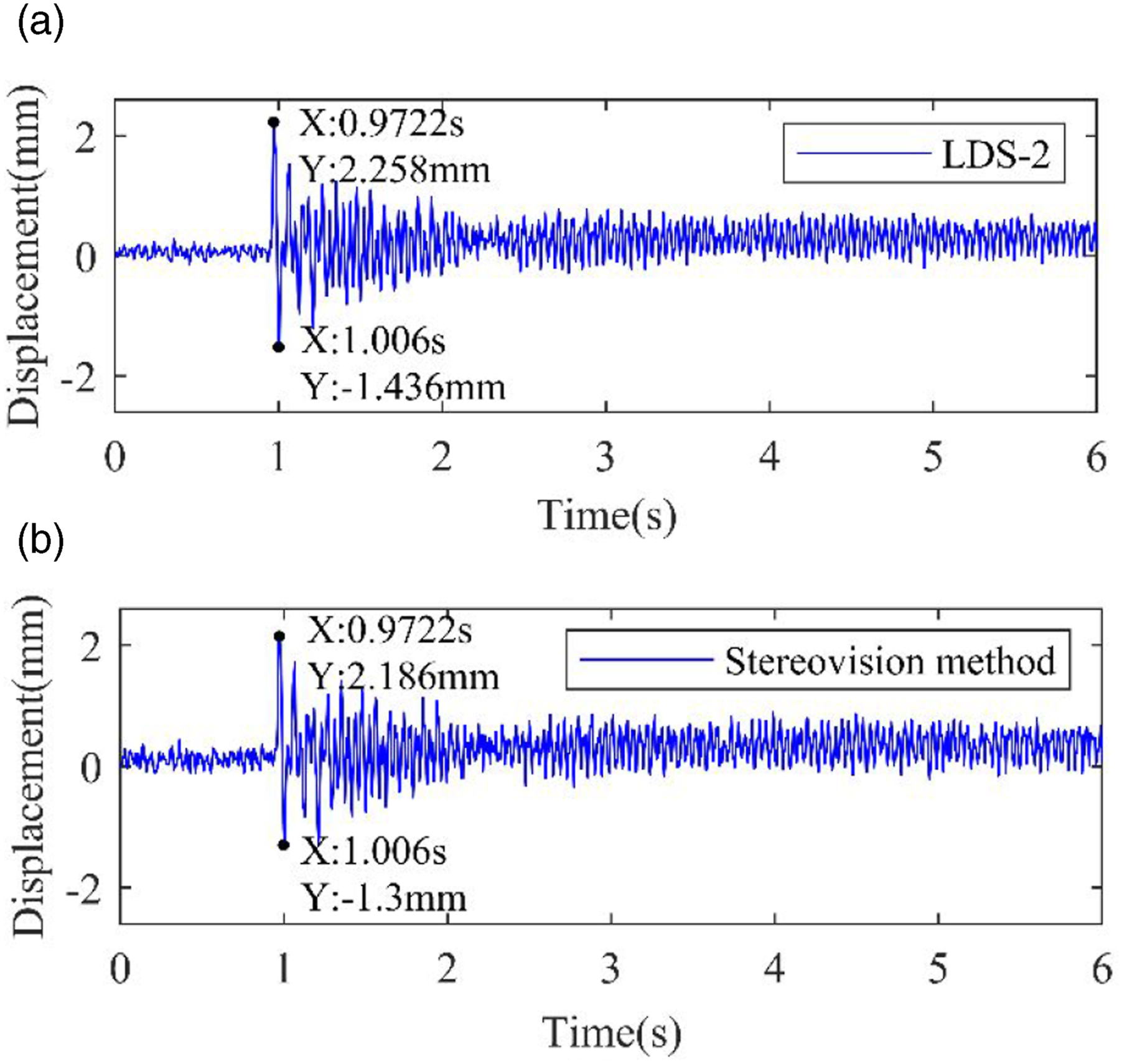
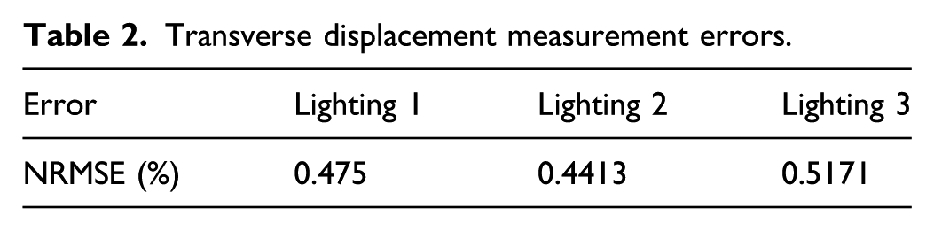
Figures 15–17 and Figures 18–20 show the transverse and lateral vibration displacements of experimental rope under three lighting conditions, and the change degree and trend of vibration curves obtained by the vision method and LDS are identical. Through calculation, the three NRMSEs between the transverse displacement data obtained by the vision method and LDS are recorded in Table 2. The errors of lateral vibration displacement results are not calculated, and the reason has been explained above. Transverse displacement-time histories with lighting 1: (a) from the laser displacement sensor, (b) from the vision method. Transverse displacement-time histories with lighting 2: (a) from the laser displacement sensor, (b) from the vision method. Transverse displacement-time histories with lighting 3: (a) from the laser displacement sensor, (b) from the vision method. Lateral displacement-time histories with lighting 1: (a) from the laser displacement sensor, (b) from the vision method. Lateral displacement-time histories with lighting 2: (a) from the laser displacement sensor, (b) from the vision method. Lateral displacement-time histories with lighting 3: (a) from the laser displacement sensor, (b) from the vision method. Transverse displacement measurement errors.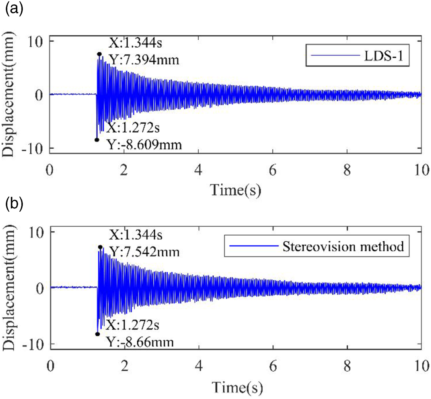
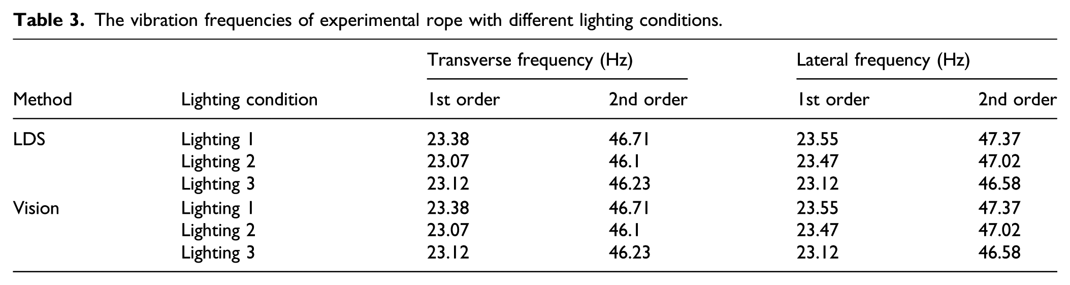
The vibration frequencies of experimental rope with different lighting conditions.
Discussion
The stereovision measurement method based on the proposed stereo matching algorithm is verified under laboratory conditions. In all experiments, the discrepancies between the measurement results obtained by LDS and stereovision method may be caused by the following reasons: (1) there is a slight change in intersection position of laser beam from the LDS and the hoisting rope; (2) the optical axis of camera is not strictly parallel to the actual 2D vibration plane of vertical rope. However, the discrepancies do not affect the consistency of the two measurement results from the two methods.
The stereovision method proposed in this paper is a non-contact and unmarked method. Its main advantages include the following: (1) it solves the problem that the sensor cannot be installed on the moving hoisting rope for vibration measurement, (2) introducing virtual marker makes the linear rope target can be located in the image without adding any substantive marker, and (3) the combination of DIP algorithm and epipolar constraint equation simplifies the process of image stereo matching. However, this method also has some disadvantages for the vibration measurement: (1) the camera cannot be moved in the current vision measurement technology, (2) in the field application, the measurement accuracy may be reduced under complex environmental conditions, and (3) the installation error of binocular camera and the small movement of camera will reduce the measurement accuracy.
In addition, although the current camera is an inexpensive device compared with LDS, a camera with higher resolution and frame rate is required to obtain higher measurement accuracy, which may increase the cost of this technology.
Conclusion
In this study, a new non-contact and non-intrusive binocular stereovision method is presented to identify the 2D vibration response of mine hoisting rope. A reference line is constructed by DIP method in image, which is perpendicular to the rope, so that a cruciform virtual marker can be formed. Therefore, the common 2D-DIC algorithm can track the moving vertical rope whose surface features in some continuous parts are very consistent without any substantive markers. A 3D-DIC algorithm is developed to locate the measuring points in the stereo images acquired by two cameras, and two matching reference lines simplify the stereo matching of measuring points in two image sequences. Two groups of free vibration test experiments of hoisting rope are carried out, and all displacement identification results from the stereovision method and LDS keep good consistency, verifying the accuracy and adaptability to changes in lighting condition of the reported method.
The stereovision measurement method is a promising tool to monitor the vibration responses of hoisting ropes in mine hoist, and these vibration parameters can be applied to the hoist reliability evaluation. In addition, it is very universal and can be extended to measure the vibration responses of other flexible cables or linear structures. In actual mine field application, several factors that may affect measurement accuracy need to be considered. For example, it is necessary to avoid optical noise as well as camera motion. Moreover, the measurement accuracy can also be improved by researching a more accurate 2D-DIC algorithm, and it needs to increase the sampling frequency and resolution of two cameras if the hoisting load and speed are both larger. As for method validation, the accurate analytical or Finite Element analysis results are possible to be used to carry out comparative analysis in the future.
Footnotes
Declaration of conflicting interests
The authors declared no potential conflicts of interest with respect to the research, authorship and/or publication of this article.
Funding
The authors disclosed receipt of the following financial support for the research, authorship, and/or publication of this article: This work was supported by the National Natural Science Foundation of China (grant number 51675520 and 51975569).