
Abstract
The aim of this study is to obtain the deflection curve equations of endplates with one to five clamping belts which allows investigating endplates deflection for uniform contact pressure distribution. Based on an equivalent mechanical model for a large fuel cell stack, the effects of the thicknesses of endplates, numbers, and positions of clamping belts are discussed, and the optimal thickness of endplate with different clamping belts is obtained, and moreover the optimal position of intermediate and outer clamping belts on the endplates. Finally, a three-dimensional finite element analysis (FEA) of a fuel cell stack clamping with steel belts and nonlinear contact elements is compared to what the equivalent mechanical beam model predicts. The result of this study shows that the equivalent mechanical model gives good prediction accuracy for the deflection behavior of endplates and the clamping force of the fuel cell stack, which is effective and helpful for the design of a large fuel cell stack assembly.
Keywords
Introduction
Nowadays, the emissions and energy use on transportation are challenge to environment all over the world.1,2 PEM fuel cell is a promising power source with high efficiency running on hydrogen with various advantages, such as low operating temperature, quick startup, and zero emission, etc.3,4 Thanks to the wide development of the electric vehicle, fuel cell can extend its advantages in modern transportation field working as the fuel cell engine for a long range and quick refuels.5,6 A large fuel cell stacks of 100 kW are essential to provide the sufficient output power for fuel cell engine, which mainly consist of bipolar plates (BPP) and membrane electrode assembly (MEA), the sealants and the end plates (EP) as shown in Figure 1.

Schematic of main components of the fuel cell stack.
The end plates are one of the main components located opposite of the fuel cell stack, which can assembly the components together with enough clamping force in order to evite the leakage of the hydrogen, and meanwhile provide a uniform contact pressure between components. The contact pressure on the multiple contact interfaces between BPP and MEA plays a key role to affect the failure or critical damage of MEA,7−9 gas transportation,10−12 and the electric resistance,13−15 eventually the performance and durability of the fuel cell stack. However, meanwhile the critical large clamping force for such large fuel cell stack easily leads to the improper deflection of endplates and moreover the non-uniform contact pressure distribution between BPPs and MEAs. As a structure of large fuel cell stack, the longitudinal structure as shown in Figure 1 (i.e. the clamping force direction of the fuel cell stack) is highly larger than the horizontal structure of the fuel cell stack, the dimension of endplates is far smaller than the longitudinal cross-section of the fuel cell stack. Especially, some methods usually used to the uniform contact pressure distribution analysis in the single cell or small fuel cell stack are not anymore suitable for such a large fuel cell stack. The analysis method for the uniform contact pressure distribution is important to a large fuel cell stack assembly.
In previous studies, many valuable works are conducted to obtain a uniform distribution of contact pressure inside the fuel cell stack. Barzegari et al. 16 designed a pneumatic endplate with proportional pressure regulator to minimize the deflection of endplate and to obtain the uniform contact pressure distribution on the MEA, however the pneumatic clamping system with gas pump, values, etc. is complex and high cost. Asghari et al. 17 early focus on influence of the thickness and deflection of the endplate on the performance of the fuel cell. A disk spring stack model and the endplate under a certain clamping force is proposed based on finite element analysis (FEA), one important criterion is obtained as the least thickness results in maximum endplate deflection and BPP stress and vice versa. An optimum thickness of the endplate is proposed to decrease the deflection of the endplate and the uneven contact pressure inside the fuel cell stack. Yu et al. 18 also consider the deflection of the endplate with the classical laminated plate theory, and the modeling of one endplate based on the FEA is established. An asymmetric shape of the endplate with a proper pre-curvature is presented in order to narrow the deflection of the endplate. The least thickness of the endplate can be obtained by this pre-curvature design. Carral et al.19,20 developed a FEA model to investigate the effect of the different numbers of cells (1–16) and their position on the endplates of the fuel cell stacks, the results revealed that with the greatest number of cells, a better uniformity of the contact pressure on MEA could be obtained. The deflection of endplates can be indicated the uniformity of contact pressure on the MEA. Liu et al. 21 also developed a finite element model based on response surface methodology to study the effect of the assembly parameters on the contact pressure of MEA. The robust solution of the assembly parameters (assembly pressure and bolt position) is achieved for PEM fuel cell stack. Alizadeh et al. 9 developed a FEA PEMFC model to study the contact pressure distribution. The effect of some parameters such as thicknesses and materials of the endplates, numbers of the cells, and position of the cell are investigated. The contact pressure distribution obtained is compared with those obtained by pressure sensitive film. Zhou et al. 22 also studied the contact pressure distribution with a finite element model to analyze the effects of clamping force. A large improvement of the uniform contact pressure distribution in the fuel cell stack has been achieved and also the performance of the fuel cell. Karvonen et al. 23 investigated the contact pressure distribution on interfaces with different endplate structures by an FE method. The simulation results revealed that uniform contact pressure distributions can be obtained if ribbed-plate structures are utilized instead of conventional endplates. Alizadeh et al. 9 simulated the contact pressure distribution over MEA with a finite element model and the effect of thickness and material properties of the endplates, numbers and position of the cells are also investigated. The contact pressure distribution over the MEA obtained by FE method with those obtained by pressure sensitive film are compared.
All these works indicate that the uniform contact pressure distributions are affected by the deflection of the endplate, cell numbers, and positions during the design of the fuel cell stack assembly. Although the finite element analysis is obviously the most common modeling method and has been achieved some important knowledges for assembly of fuel cell stack, however the FE model is often concerned of complex simulation and huge calculation resource. Moreover the contact behaviors between BPPs and MEAs also add extra great difficulties to simulate the large-scale fuel cell stack for accurate results. For this reason, some new methodologies for large fuel cell stack are valuable to realize for efficient analysis. Lin et al.24,25 proposed an efficient assembly analysis method with a simplified equivalent stiffness mechanical model for a large PEM fuel cell stack, and compared with a three-dimensional FE modeling. The results showed that the equivalent stiffness model was effective and could be feasible to predict the contact pressure distribution with an acceptable tolerance. Yu et al. 26 established a simplified beam model to minimize the deflection of the endplate in order to obtain the uniform contact pressure, meanwhile ensure an appropriate flexural rigidity, weight of the endplate structure with proper thickness. Qiu et al. 27 also proposed a continuous equivalent model to predict the contact pressure in the fuel cell assembly, the results showed that the equivalent model is feasible and effective for the study of the contact pressure distribution and assembly design of fuel cell stack.
As introduced in literature review, few studies have been conducted on the endplate’s deflection during assembly of a large fuel cell stack, the endplates are supposed to be a rigid body and the deflection of the endplate is ignored. Moreover, most research has focused on PEM fuel cell stack with few cells. In addition, the research has not investigated an efficient mechanical method of the endplates deflection for the uniform contact pressure distribution. For this reason, this paper will consider the issue of an endplates deflection clamping with different steel belts, which is one of the practical methods used to control uniform contact pressure distribution of PEM fuel cell. Furthermore, an equivalent beam model of the endplate is firstly proposed with different clamping belts for a large fuel cell stack. Optimal range of the deflection of endplates combined with different pattern of the geometry of endplates, the numbers and position of clamping belts should be carried out, in order to obtain as uniform as possible for the contact pressure during a fuel cell stack assembly.
Equivalent mechanical beam models of the endplates
Considering convenient assembly of a fuel cell stack, three main contents will be discussed here in order to narrow the deflection range of the endplates for uniform contact pressure distribution: (1) different numbers of the clamping belts; (2). balance of different numbers of the clamping belts and the thickness of endplates; (3) relative position of the clamping belts on the endplates.
Compared to the total dimension of the whole fuel cell stack with 370 unit cells, 28 the end plates and the clamping steel belts can be simplified as an equivalent beam model with clamping forces in the longitudinal direction of the end plate. The assumptions of this simplified mechanical model are: (1) without the steel belts in the model, the clamping force are directly applied at the middle center of steel belts; (2) the elastic modulus of the sealants is much larger than the MEA, and the restoring force of sealant cannot be ignored; (3) steel belts always uniformly contact with the end plate without gap.
Equivalent mechanical beam model
The equivalent mechanical beam model of the endplates clamping with steel belts is summarized and compared in Table 1. During the assembly process of fuel cell stack, the upper and lower endplates are actually assembled and deformed by the clamping steel belts, and the loads (clamping force) are applied by the steel belts, meanwhile, the sealants supply the react forces on the endplates. Since the endplate is deformed in bending under the clamping force with steel belts, wherein the endplate is equivalent to be one beam element, and the steel belts are equivalent to be the movable brace, the react force
Summarize and comparison of different mechanical model of the endplates with clamping belts.

The distribution of the clamping steel belts applied on the endplate is symmetric dues to the symmetric endplate structure and symmetric applied clamping belts. Here half of the equivalent beam structure is established in Figure 3 corresponding to the full model in Figure 2, and if the symmetrical cross-section of the beam is at the position of the movable brace (i.e. Figure 3(a), (c) and (e)), or the symmetric constraint can be added as shown in Figure 3(b) and (d).
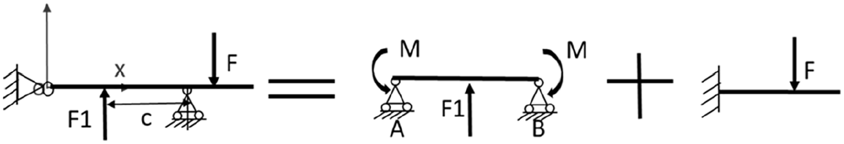
In order to solve the deflection and slope equation, the equivalent mechanical model of the endplates with clamping belts in Figure 3 is transformed into equivalent determinate beam model as shown in Figure 4. Then based on the material mechanics method, it is an equivalent system and the deflection curve and cross section slope equation can be individually obtained. F1 and F2 represent the clamping force by belts applied on the endplate, l represents the half length of the endplates, and a is the distance of the middle of sealant to the end of the endplates, b is the distance of the first clamping belt to the end of endplates, and c is the distance of the second clamping belt to the end of endplates. Since the clamping belts are uniform distribution for the uniform contact pressure between contact components, c can be represented by l, b, and n, where n is the numbers of the clamping belts applied on the endplates.
Deflection curve equations of endplates with one to five clamping belts
The following will discuss for the deflection curve equation of the endplate clamping with one to five belts corresponding to Figure 4(a) to (e):
Part I: Deflection curve equation of the endplate clamping with one belt
Based on the differential equation of the deflection curve equation by material mechanics method, the study of deflection curve equation of the endplate with one clamping belt can also be divided into two cases by the position of clamping belt x applied on the endplates:
If


Boundary conditions:


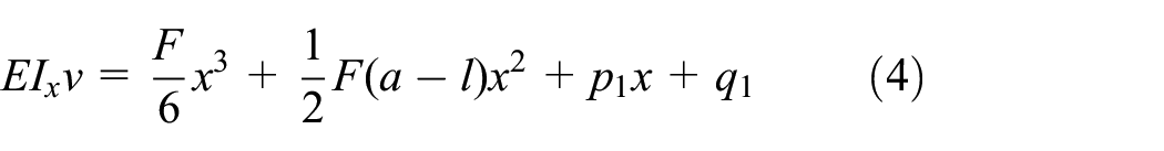
According to equations (3) and (4) and the boundary conditions, then

If


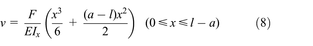
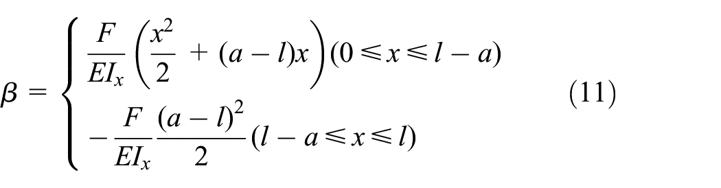
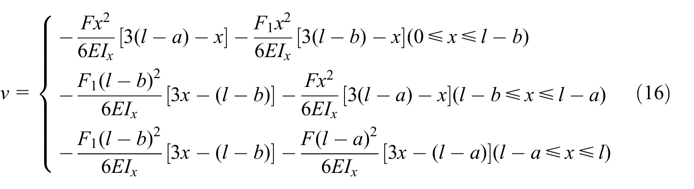
Finally, the deflection curve equation ν and cross section slope equation β of the endplate with one clamping belt can be concluded as:

Part II: Deflection curve equation of the endplate clamping with two belts
If the endplate is clamped with two belts, there has several loads comes from clamping belts and sealants. The superposition method is suitable to solve this case. The deflection and cross section slope of the endplate under several loads can be composed by the superposition of the deflection and slope under loads. The Figure 4(b) can be divided into two substructures shown in Figure 5.

Equivalent model of endplate with two clamping belts based on superposition method.
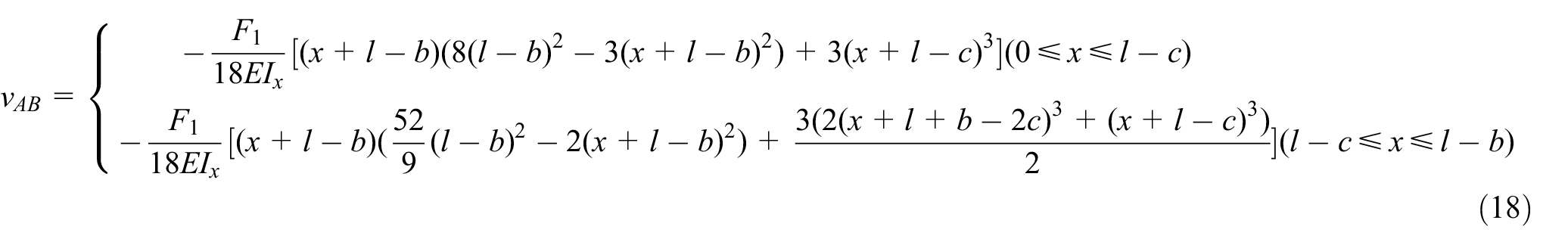
The deflection curve equation of segment AB as shown in Figure 5 can be written as:
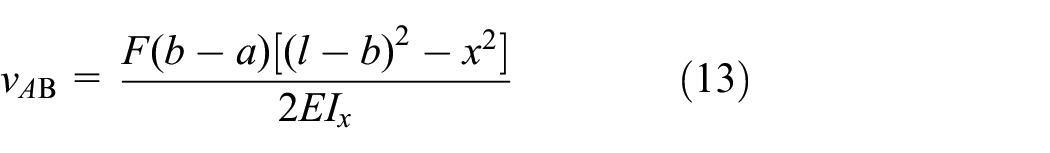
Then the deflection curve equation of the right part except AB is:

Based on equations (13) and (14), the deflection curve equation of the endplate with two clamping belts can be written as:

Part III: Deflection curve equation of the endplate clamping with three belts
If the endplate is clamped with three belts, there also has several loads applied on the endplate, and the deflection curve equation can also be similarly obtained as above based on the superposition method shown as:
Wherein the relationship between the restoring force of sealant F and the clamping force of belt F1 is:

Part IV: Deflection curve equation of the endplate clamping with four belts
If the endplate is clamped with four belts corresponding to Figure 4(d), the whole model can be divided into two substructures as shown in Figure 6: one substructure is the endplate with two clamping belts, which is the same as part II.
Equivalent model of endplate with four clamping belts based on superposition method.
The other substructure is the segment AB, the deflection curve equation can be written as:

And the relationship between the reaction force of sealant F and the clamping force of belt F1 is:

Similar to the deflection curve equation of the endplate clamping with two belts in part II, based on superposition method, the deflection curve equation of the endplate clamping with four belts is shown as:

Part V: Deflection curve equation of the endplate clamping with five belts
If the endplate is clamped with five belts corresponding to Figure 4(e), the equivalent model can be regarded as the superposition of three cantilever substructures. It is similar to obtain the deflection curve equation as shown:

Wherein the relationship between the reaction force of sealant F and the clamping forces of belt F1 and F2 is shown as:


Optimize the deflection of the endplates
The deflection curve equations of the endplate with different clamping belts have been obtained based on the equivalent mechanical model, which can be contributed to evaluate the effects of different numbers, position of clamping belts on the endplates, and thickness of the endplates on the uniform contact pressure distribution.
Deformation height to evaluate the deflection of the endplates
As the deflection of the endplates is a variable correlated to the position x of the clamping belts based on the formula of the deflection curve equation ν. In this part, one parameter can be defined to represent the comprehensive effect of the average deflection of the endplate. At case of three steel belts as an example in Figure 7, the sum of the shaded area of the endplates deflection in Figure 7(a) and the width d of the flow field shown in Figure 7(b) are considered, their ratio will be taken as the evaluation factor which can be named as “deformation height” as common use for the average deflection of the endplate. 29

Schema of deformation height of the endplate: (a) shaded area of the endplates deflection and (b) width of the flow field.
The deformation height can be obtained by integration of the deflection curve of shaded area and the width of flow field d, and expressed as:

Where d is the 1/2 flow field width,
Influence of the different numbers of the clamping belts
The deformation height of the endplate with different numbers of clamping belts will be studied in this part. Except the numbers of clamping belts is variable, the other dimension parameters are constant as shown in Table 2. The end plate is rectangular cross-section, with cross-section length b0 and cross-section height h0, elastic modulus of the end plate is 158 GPa, all these data come from one 55 kW self-design fuel cell stack with 270 cells for vehicle. The fuel cell stack is assembled by an air cylinder, the restoring force F of the sealant can be obtained by:
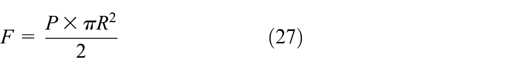
Wherein p is pressure of air cylinder during the stack assembly, here p is 0.6 MPa; R is the cylinder radius, here R is 100 mm.
Dimension parameters of the end plate clamping with steel belts.

The Figure 8 individually shows the deflection curve of the end plate with one to five clamping steel belts, the horizontal coordinate is the position of the endplate to its symmetric center, and the longitudinal coordinate is the deflection of the end plate obtained based on the deflection curve equations of the endplate.

Deflection curve of the end plate clamping with one to five belts.
At the case of one clamping steel belt applied, since the clamping force is applied at the middle of the endplate for symmetric load, the maximum deflection of the endplates appears at two ends of the endplate which will easily result in the leakage of the hydrogen and the improper distribution of the contact pressure inside the fuel cell stack. At the case of two clamping belts applied, since the clamping force is applied at the two sides of the endplate where corresponds to the position of the sealants, the endplates will swell and the maximum deflection exists at the middle of the endplate, which will result in the small contact pressure distribution around the center of the fuel cell stack. However, at the case of three to five clamping belts, the deflections of the endplate are small compared to the cases with one to two clamping belts which will obtain the relative uniform distribution of contact pressure in the fuel cell stack. Therefore large numbers of the clamping belts on the endplate have an important influence to decrease the deflection of the endplate and meanwhile to enhance the uniform contact pressure distribution.
However it is not too obvious to find the difference among the deflections caused by different numbers of clamping belts, especially for the three to five clamping belts case. Therefore the deformation heights defined in equation (26) of the endplate with one to five clamping belts are presented in Figure 9, wherein the horizontal coordinate is the numbers of the clamping belts, and the longitudinal coordinate is the natural logarithm of the deformation height h of the endplates.

Deformation height of the end plate with one to five clamping belts.
In Figure 9, it is obvious to find that the deformation height of the endplate decreases with the numbers of the steel belts, but the difference with two and three clamping belts is particularly obvious which is similar to Figure 8. However the advantage of the defamation height can be presented to indicate the small difference among the deflections at the case of three to five clamping belts which cannot be obviously found in Figure 8. Therefore, the deformation height of the endplate will be applied to present the deflection of the endplate. And it can also be found that it is better to have at least three clamping belts for the assembly of a fuel cell stack which corresponds to a relative small deformation height in Figure 9, therefore three or four clamping steel belts will be commonly recommended during the assembly of a fuel cell stack.
Balance the different numbers of the clamping belts and the thickness of endplates
Although the large thickness of the endplates is effective to decrease the deflection of the endplate introduced in previous studies, however the small thickness will reduce the volumetric power density of fuel cell stack. Thus it is necessary to balance the numbers of steel belts and thickness of endplate while keeping the same deformation height of the endplates. Except the thickness of the endplate b0, the other parameters are also the same as listed in Table 2. The relationship between the deformation height, different numbers of the clamping belts and thickness of the endplates can be obtained by the equivalent mechanical model as shown in Figure 10.

Relationship between the numbers of clamping belts and thickness of end plates.
In Figure 10, the horizontal coordinate is the thickness of endplate b0, and the longitudinal coordinate is the natural logarithm of the deformation height. Considering of the thickness of the endplates corresponding to the different numbers of clamping belts, two different zones are divided to present. In the zone A1, it is interesting to find that under the same deformation height, different clamping steel belts individually correspond to five different thickness of the endplate: for example one steel belt corresponding to the thickness of endplate ln1_e, two steel belts corresponding to the thickness of endplate ln1_f, three steel belts corresponding to the thickness of endplate ln1_d, four steel belts corresponding to the thickness of endplate ln1_b, and five steel belts corresponding to the thickness of endplate ln1_a. It is obvious to find that large numbers of clamping belts can obtain less thickness of the endplate under the same deformation height. Therefore, it is practical to determine numbers of clamping steel belts and the thickness of endplate by using this practical curve in Figure 10 during the assembly design of a fuel cell stack for engineers.
Based on this analysis, large numbers of clamping belts are effective way to decrease the thickness and weight of endplates without increasing any cost. For example in this case of Figure 10, two clamping belts corresponding to 40 mm thickness of the endplate, however if three clamping belts are applied to clamp the fuel cell stack corresponding with only 18 mm thickness of the endplate under the same deformation height. It is impressive to find that 55% the reduction of the thickness of end plate is achieved and by only adding one clamping belt from two to three. However it should pay attention to the zone A2 in Figure 10, not all the clamping belts can correspond to a proper thickness of the endplates, which resulted in the large difference between the deformation heights.
Influence of the outer and intermediate position of the steel belts on the endplates
The endplates are clamped by several steel belts for assembly a large fuel cell stack, the position variable of the clamping belts on the endplates have important influence to the deflection range of the endplate. Since the position of clamping steel belts represents the position of the clamping force on the endplates, and moreover influence the uniformity of contact pressure distribution. As discussed, three or four clamping belts are enough to obtain relative small deflection of the endplate. The outer steel belt and intermediate steel belt on the endplate are two important positions to assembly the fuel cell stack.
The effects of the position of the outer steel belt and intermediate steel belt on the endplate will be individually discussed: (1) the position variable of the outer steel belt in three or four clamping belts cases, defined as the variable b, that is the distance of the outer clamping steel belt to the end of the endplate as shown in Figure 4(b); (2) the position variable of the intermediate steel belt, defined as the variable c, that is the distance of the intermediate steel belt to the end of the endplate as shown in Figure 4(d).
In order to well represent the influence of the relative position of the steel belts for the deflection, the coefficients of position variable kb and kc of the clamping steel belts on the endplates are defined as the ratio of the position variable b and c compared to the half-length of the endplate l as shown in the equations (28) and (29).


For the three clamping steel belts, the position range of the outer steel belt on the endplate is defined as 7 × l/8 (

Schematic diagram of the position of three or four clamping steel belts on the endplate: (a) position variable of the outer steel belt with three clamping steel belts and (b) position variables of outer and intermediate steel belt with four clamping steel belts.
Based on the equivalent mechanical model, the deformation heights of the endplate with the position variable coefficient kb are individually shown in Figure 12 for three and four steel belts. As shown Figure 12(a) of the three clamping steel belts case, the deformation height of the end plate increases with the position variable coefficient kb of the outer steel belt, and which is close to an exponential growth. When the range of kb is about 0.125–0.3, the range of deformation height of the endplate is relative small which means the deflection of the endplate is also small, that is better to the uniform contact pressure distribution. But if kb exceeds 0.125, the range of the deformation height of the endplate increases. As discussed in equation (26), the deformation height represents the deflection of the endplates. Therefore, in order to decrease the deflection of the endplate with three clamping steel belts, it is necessary to control the narrow range of the position variable coefficient of the outer steel belt, which means the position of the outer steel belt on the endplate is better near to the position of the sealants. The deformation height is minimal when the position of the outer steel belt is l/8, that is the position of the outer steel belt b is just on the position of the sealants on the endplates.

The deformation height of the endplates with the position variation coefficient kb of the outer steel belts for three and four clamping belts: (a) three clamping belts case and (b) four clamping belts case.
For the four clamping steel belts case as shown in Figure 12(b), the deformation height of the endplates initially increases and after a peak of kb = 0.35, and then decrease with the position coefficient kb of the outer steel belt. In order to obtain a minimum deformation height, for the endplate with four clamping steel belts, the position variable coefficient kb of the outer steel belt is also 0.125 in the Figure 12(b), that is the position of the outer steel belt is located at the position of the sealants as l/8 on the endplates. Therefore, in order to narrow the range of the deformation height of the endplate as small as possible, the optimal position of the outer steel belt is recommended at l/8 on the endplate where it is at the position of the sealants.
Since the intermediate steel belts with three clamping belts is just at the middle of the endplate, here the position variable of the intermediate steel belt is only presented in the four clamping belts case. The deformation height of the endplate with the position variable coefficient kc for four clamping steel belts is shown in Figure 13. It can be found that the deformation height of the endplate decreases with the position variable coefficient kc, the deformation height can be minimal with kc = 1, that is the position of the intermediate steel belt c is l which means intermediate steel belt close to the middle of the endplate, the deformation height of the endplate will be minimum. Therefore the intermediate steel belt for the four clamping steel belts should be arranged as close as possible to the middle of the endplate, and then the four clamping steel belts work as the three clamping steel belts. It also indicates that if the numbers of the clamping belts are odd (for three or five steel belts), the intermediate steel belt can be arranged at the middle of the end plate in order to benefit the narrow range of the deflection of the endplates.

The deformation height of the endplate with the position variation coefficient kc of the intermediate steel belt for four clamping belts.
In summary, based on the analysis of the position variable kb and kc of the clamping steel belts on the endplates, in order to narrow the deflection of the endplate and improve the uniform contact pressure distribution in the fuel cell stack, odd numbers of the clamping belts for the fuel cell stack assembly are recommended and in detail, the intermediate clamping belt on the endplates is better located at the middle and the outer clamping belts on the endplate are better near to the sealants.
Validate the equivalent mechanical model with a finite element analysis
As analyzed above, in order to validate this equivalent mechanical model, a finite element model of a fuel cell stack with BPPs, MEAs, sealants and endplates is established, and straight flow channel in the flow field is enough to study the influence of the contact pressure distribution between BPP and MEA. A 3D symmetric model with its meshing is shown in Figure 14 considering of the limit calculation resource.

A finite element 3D 1/8 modeling of the endplate with BPP and MEA: (a) A 3D model and (b) meshing.
The dimension and material characteristics as shown in Table 3 are all comes from the self-design fuel cell stack of 55 kW with 270 cells. The boundary condition is applied on the symmetric surface as the symmetric constraint, and the clamping force is directly applied on the contact surface between the endplate and steel belts as the same as the equivalent model. Based on this finite element analysis, the effect of different numbers and position of the steel belt on the end plate will be validated and compared to what the equivalent mechanical beam model has predicted.
Main material characteristics of the fuel cell components.

The variance of contact pressure distribution with the different distance between steel belt and the sealant is shown in Figure 15, wherein kb is the position variable coefficient of the outer steel belt in equation (28) and ka is the position variable coefficient of the sealants. ka can be defined as:

Where a is the distance of the sealant to the end of the endplate. Here,

Effect of distance between sealant and different numbers of steel belts on the contact pressure distribution.
The Figure 16 presents the variance of contact pressure with different numbers of clamping steel belt and thickness of the rectangular endplate obtained by the finite element analysis. As shown in Figure 16, the variance of the contact pressure decreases with the increasing of the numbers of the steel belts, in detail, the difference is small with three to five steel belts as shown in the local zoom part which is in coincidence with the results shown in Figure 8. Moreover the variance of the contact pressure decreases with the increasing of the thickness of the endplate, which is also in coincidence with the results shown in Figure 10. Therefore, it can be found that the variance of contact pressure decrease with the thickness of the endplate and with the numbers of clamping belts, which corresponds to the result obtained by the equivalent mechanical model.

Finite element verification result of the matching relationship between the number and the thickness of steel belts.
Therefore, the analysis of this part can validate the equivalent mechanical model of is effective and can be efficient to study the deflection of endplate and the uniform contact pressure distribution of fuel cell stack with relative limit calculation resource compared to the FEA. It is also practical for engineers of the vehicle enterprise to quick and convenient design during a fuel cell stack assembly.
Conclusion
An equivalent mechanical model is established to efficiently analyze the deflection range of the endplates under the combined action of clamping belts and sealants. Considering the several important variances during fuel cell stack assembly, including numbers of clamping belts, outer and intermediate position of clamping belts on the endplates, and thickness of endplates, in order to narrow the deflection range of the endplate and improve the uniform contact pressure distribution, the allowable or the optimal range of the deflection of the endplate is obtained. Based on the analysis in the present paper, the following conclusions can be obtained.
Firstly, with the increase of the numbers of clamping belts, the allowable range of the deflection of the endplate obviously becomes small. The factor of deformation height can be indicated the deflection of the endplate and at least three clamping steel belts are proposed for a small deflection of the endplates. Secondly, the large numbers of the clamping belts can significantly reduce the thickness of the endplates to obtain a small deflection of the endplate and a practical curve is proposed to balance the relationship between the thickness of the endplate and the numbers of the clamping belts. Thirdly, the position of the outer clamping belts close to the sealant will lead to a smaller deflection of the endplate and uniform contact pressure distribution. Finally, the intermediate position of the clamping belts is at the middle of the endplate which can minimize the deflection of the endplate and improves the uniformity of contact pressure if the numbers of clamping belts are odd. This study can provide the theoretical basis and design criteria for uniform contact pressure distribution during the fuel cell stack assembly.
Footnotes
Handling Editor: James Baldwin
Declaration of conflicting interests
The author(s) declared no potential conflicts of interest with respect to the research, authorship, and/or publication of this article.
Funding
The author(s) disclosed receipt of the following financial support for the research, authorship, and/or publication of this article: This work was supported by Natural Science Foundation of Shanghai (19ZR1460000).