
Abstract
Carbon fiber reinforced polymer (CFRP) is widely used in the aerospace field due to its light weight and high strength. The CFRP milling process is prone to damage such as burrs and tears. The cutting force is closely related to the damage of CFRP and tool wear. In this paper, a back propagation (BP) neural network model of cutting force and edge force coefficients was established. The model considers the effects of instantaneous uncut chip thickness, fiber cutting angle, spindle speed, and axial depth of cut. The unidirectional CFRP laminate instantaneous milling model considering the cutting edge force was further established. The instantaneous milling force prediction model was extended to multi-directional CFRP laminates. And the relationship between the damage mechanism of CFRP and the instantaneous milling force was analyzed. Experiments have proved that the instantaneous milling force prediction model built in this paper has high accuracy.
Introduce
Carbon fiber reinforced polymer (CFRP) has a series of advantages such as high specific strength, corrosion resistance, low thermal expansion coefficient, and strong shock resistance. Therefore, CFRP is more and more widely used in the fields of automobiles and aerospace.1–4 CFRP parts are produced near net shape, but a large amount of secondary processing such as drilling and milling is still required during the equipment process. CFRP is a composite material composed of carbon fiber as the reinforcing phase and resin as the matrix. Due to the difference in the properties of carbon fiber and resin, it is easy to form damage such as delamination and tearing burrs during processing.5,6 CFRP is a hard and brittle material, and the tool wear in processing engineering is also very serious. The cutting force is an important machining index in the machining process, and it has an important influence on the stability of milling, the wear rate of the tool and the quality of the workpiece. Therefore, accurate prediction of CFRP cutting force is of great significance to the optimization of machining parameters, tool design, and improvement of machining efficiency and stability.
International scholars have done a lot of research on CFRP milling force prediction. Zaghbani et al. 7 used a straight-edge polycrystalline diamond (PCD) milling cutter to carry out multi-directional CFRP laminate milling experiments. Through the experimental design, the influence of resonance and other factors on the cutting force signal was eliminated, and the milling force model is established. The predictive force obtained by the model is in good agreement with the measured force. Karpat et al. 8 used empirical functions to establish the instantaneous specific cutting energy prediction model during CFRP slot milling, and analyzed the relationship between instantaneous cutting force and CFRP machining quality. Sheikh-Ahmad et al. 9 used regression model and artificial neural network model to establish the CFRP milling force prediction model, and found that the prediction accuracy of the artificial neural network model was better than the regression model. Slamani et al. 10 studied the influence of the ratio of cutting speed to feed rate on milling force, and established an empirical formula for predicting milling force considering tool wear. The results show that the resultant milling force increases with the ratio of cutting speed to feed rate. Su et al. 11 took the milling of woven CFRP as the research object, and successfully predicted the cutting force using the average specific cutting energy method. The prediction model took into account the impact of spindle speed, feed speed and the depth of cut. Experiments had proved that the relative error between the predicted value and the experimental value is less than 10%. Kalla et al. 12 established a force model for predicting the milling of CFRP by converting the cutting specific energy of right-angle cutting into the cutting specific energy of bevel cutting. Min et al. 13 comprehensively considered the effects of axial depth of cut, feed speed, spindle speed and fiber cutting angle on instantaneous milling force, established a unidirectional CFRP instantaneous milling force prediction model, and extended the model to multi-directional CFRP laminate. He et al. 14 established a unidirectional CFRP milling force model considering the edge force based on the empirical formula method. The experiment proved that the accuracy of the model was high. But the model did not consider the influence of the spindle speed, feed speed and other processing parameters.
Accurate prediction of CFRP instantaneous milling force is of great significance for studying the mechanism of tool wear and material damage. From the research status at home and abroad, it can be known that most of the research objects of the published milling force model are unidirectional CFRP, and the influence of edge force and axial depth of cut are not considered. However, the edge effect has an important influence on the total cutting force and cannot be ignored, 15 CFRP used in aerospace is dominated by multi-directional laminates. The CFRP milling force is decomposed into the edge force and cutting force in this paper, and the method for determining the edge force and cutting force is derived. Then a prediction model of instantaneous milling force of unidirectional CFRP laminates considering the edge force is established based on BP neural network. The linear superposition method is used to extend the unidirectional CFRP laminates prediction model to multi-directional CFRP laminates. The model not only can more accurately predict the CFRP instantaneous milling force under different axial cutting depth, spindle speed, instantaneous chip thickness and fiber cutting angle, but also reveals the relationship between cutting force and machining damage.
CFRP milling force analysis
Instant fiber cutting angle and uncut chip shape
The CFRP used in aerospace is mostly multi-directional CFRP laminate, which is composed of four typical laminating directions (0°, 45°, 90°, 135°) of unidirectional CFRP layer by layer, as shown in Figure 1. Therefore, analyzing the milling process of unidirectional CFRP laminate is the basis for analyzing multi-directional CFRP laminate.
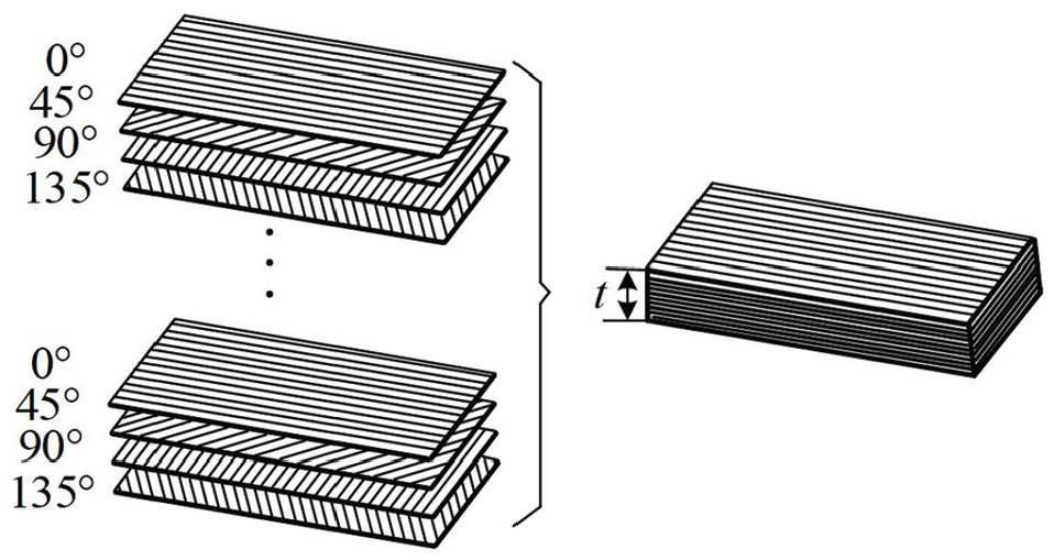
Schematic diagram of multi-directional CFRP laminate.
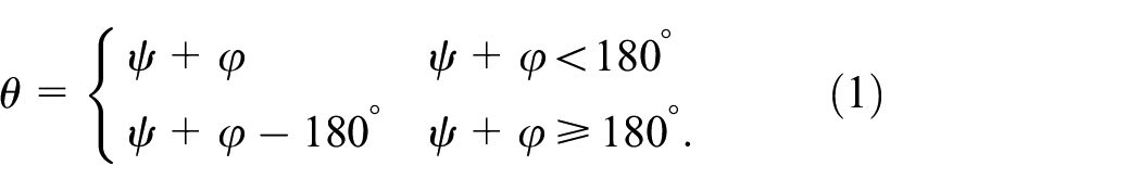
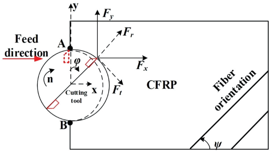
CFRP is a typical anisotropic material. The cutting force is not only related to processing parameters such as spindle speed and feed rate, but also affected by the fiber cutting angle θ. This paper takes the commonly used double-edged straight milling cutter in CFRP as an example to study the CFRP milling force. The specific parameters of the milling cutter are shown in section 3. Figure 2 is a schematic diagram of unidirectional CFRP milling, where the fiber layer direction Ψ is 0°, θ is the fiber cutting angle, af is the feed speed (feed per tooth) and φ is the tool rotation angle. For the convenience of description, when the tooth is at point A and point B, the tool rotation angle is recorded as 0° and 180°. Therefore, the value range of φ is 0∼180°. For unidirectional CFRP laminates, the fiber cutting angle can be expressed as 13

Schematic diagram of unidirectional CFRP milling.
During the milling process, the cutter teeth are in cycloidal motion. The uncut chip of a single tooth is crescent shape. And the instantaneous chip thickness tc changes with the change of the tool rotation angle φ during the milling process. 13

Modeling method of instantaneous milling force of unidirectional CFRP laminates considering edge force
Figure 3 is a schematic diagram of the cutting force of a single tooth in the CFRP milling process. Fx and Fy are the instantaneous forces in tool feed direction (X direction) and perpendicular to the feed direction (Y direction) in the horizontal plane during the tool milling process, which were measured by the dynamometer. Ft and Fr are the tangential force and radial force in the milling process, and the directions of Ft and Fr change at any time during the milling process. The relationship between the two can be derived from the geometric relationship:

Schematic diagram of CFRP single tooth milling force.
According to the classic milling force model of materials, the cutting force is equal to the product of the correlation coefficients and the cutting area, and the instantaneous milling force can be expressed by the following formula16,17

In the formula, KSt and KSr are the tangential cutting force coefficient, radial cutting net cutting force coefficient; KBt and KBr are the tangential edge force coefficient and the radial edge force coefficient. For CFRP; the instantaneous cutting area Ac can be written as the following formula

where ap is the axial depth of cut,

Method for determining instantaneous cutting force and edge force coefficients
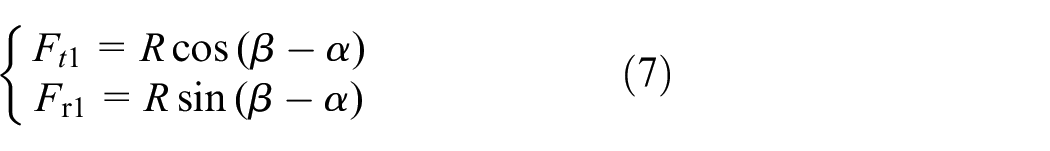
The total cutting force in CFRP processing process includes fiber cutting force, ploughing, and pressing force. International scholars have proposed a cutting force analysis model that considers fiber cutting force, ploughing, and pressing force at the same time. This model divides the cutting area into two parts, as shown in Figure 4. Region 1 is the cutting action area, and the cutting force is the net cutting force R.14,15 From the geometric relationship:

Schematic diagram of cutting force analysis. 15
Among them, Ft1 and Fr1 are respectively the tangential and radial cutting force components of region 1 force. Region 2 is the pressing region where the ploughing and friction effects are dominant. In region 2, the pressure perpendicular to the cutting direction is P. According to Coulomb friction law

where Ft2 and Fr2 are respectively the tangential and radial cutting force components of region 2 force.
Combining equations (7) and (8) can obtain the total cutting force in the tangential and radial directions

From equation (9) we can get
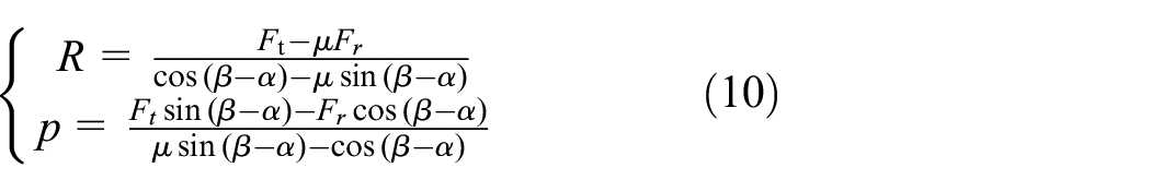
According to equations (6) and (9), we can get 14
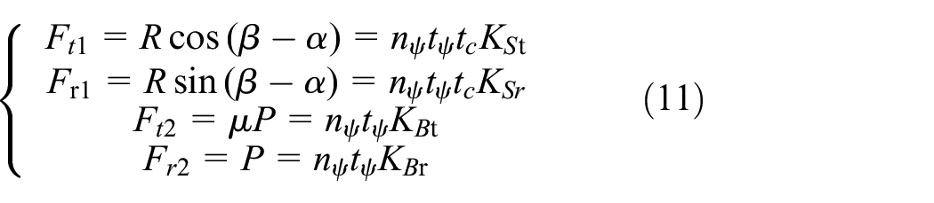
From equation (11) we can get the coefficients KSt, KSr, KBt, and KBr, and the expression is

It is noted here that the rake angle α is zero for the tool used in this experiment. The friction angle β can be determined from equation (13) when μ is known:

In the above formula is the friction coefficient. The friction coefficient between the carbon fiber and the tool is 0.12–0.14, and this paper takes 0.13. 18
Establishment of instantaneous milling force model for multi-directional CFRP laminate based on linear superposition method
The essence of milling multi-directional CFRP laminates is to simultaneously mill unidirectional CFRP laminates with different laying directions. Therefore, the milling force is the sum of the milling force for simultaneous milling of unidirectional laminates with different ply angles. 19

Due to the effect of curing between multi-directional CFRP laminates, CFRP is constrained by adjacent layers in multi-directional CFRP laminates. The cutting force is quite different from unidirectional CFRP laminates. Therefore, this paper introduces the multi-directional plate milling force correction factor.

where
CFRP milling experiment design
The machine tool used in the experiment is an XK714D vertical machining center equipped with Siemens 828D system. The CFRP was fixed by bolts. The cutting forces in X, Y, and Z directions were measured by a Kistler 9272 three-way piezoelectric dynamometer. The data acquisition frequency is 2000 HZ. The experimental layout is shown in Figure 5. The materials used in the experiment are 4 mm thick T700/epoxy resin LT-03A unidirectional laminate and multidirectional laminate. The tool used is a double-edged straight milling cutter with a diameter of 6 mm. The material of the cutting edge is diamond. The rake angle of the milling cutter is 0°, and the back angle is 10°. The radius of the tool tip arc is 7 μm, as shown in Figure 6.

Experimental layout: (a) data acquisition device and (b) workpiece clamping diagram.
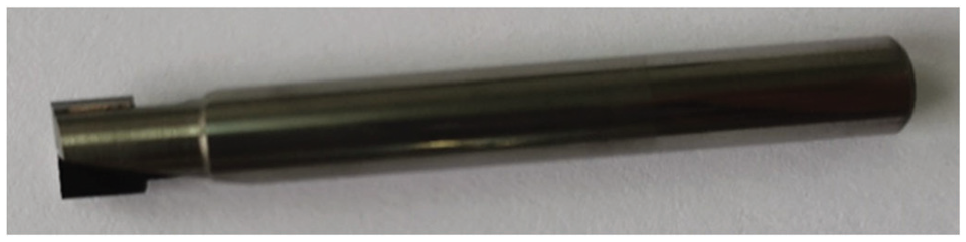
Milling cutter used in the experiment.
In order to accurately establish the instantaneous milling force prediction model, four lay-up directions of unidirectional CFRP and multidirectional CFRP were used for milling experiments. The milling experiment adopted a full-factor experiment design, and 27 experiments were performed for each CFRP. The milling width is 6 mm, and the parameters are shown in Table 1.
Experimental parameters.

CFRP instantaneous milling force prediction model based on BP neural network
Instantaneous milling force modeling of unidirectional CFRP laminate
In this section, a unidirectional CFRP laminate milling force prediction model is established based on the data collected in the experiment. In recent years, common milling force prediction methods include linear regression, response surface method and neural network method. BP neural network is a data prediction method that uses the method of tutor-guided learning for multi-level feedback and has strong nonlinear fitting capabilities. And there is a strong non-linearity relationship between the correlation coefficients and the processing parameters. Studies have shown that for anisotropic, multi-layered structure and multi-processing parameter CFRP milling force prediction, the neural network has higher accuracy than other methods. 20 Therefore, the neural network method is adopted in this paper. From the analysis in section 2.2, we only need to know KSt, KSr, KBt, and KBr to accurately predict the unidirectional plate milling force. The model building steps are as follows:
First, the cutting force was measured by the dynamometer. The instantaneous Fx and Fy corresponding to slot milling were gotten on stable cutting. Figure 7 shows the three-way milling force when Ψ = 0, af = 0.1 mm/tooth, n = 3000 rpm, ap = 4 mm. The force in Z-direction is almost 0.
According to formula (3), the instantaneous cutting forces Fx and Fy are converted into instantaneous radial force Fr and instantaneous tangential force Ft, as shown in Figure 8.
The instantaneous values of KSt, KSr, KBt, and KBr corresponding to the instantaneous radial force Fr and instantaneous tangential force Ft were find by equations (10) and (12), as shown in Figure 9.
With ap, n, tc, and θ as independent variables, the prediction model of KSt, KSr, KBt, and KBr was established by BP neural network. According to formula (6), the prediction of unidirectional CFRP instantaneous milling force is completed.

Three-way milling force.

Tangential and radial milling forces.

Instantaneous values of KSt, KSr, KBt, and KBr.
The schematic diagram of the cutting force coefficient prediction neural network model is shown in Figure 10, which includes the input layer, the hidden layer, and the output layer. The number of neurons in the input layer is 4, which are the axial depth of cut, spindle speed, fiber cutting direction angle and uncut chip thickness. The number of neurons in the hidden layer is 150. The output layer has four neurons, which are KSt, KSr, KBt, and KBr. The transfer function is “logsig.” The learning rate of the neural network is set to 0.1. The learning accuracy is 4 × 10⁻⁵. From the 3312 data points obtained in the experiment, 2318 data points were randomly selected as training samples (training set), 497 data points were used as test samples (test set), and 497 data points were used as verification samples (verification set). The training results are shown in Figure 11. It can be found that the determination coefficient R is greater than 0.95, and the data fit is better.

BP neural network model.

The correlation between experimental values and predicted values of KSt, KSr, KBt, and KBr.
Instantaneous milling force modeling ofmulti-directional CFRP laminate
According to the 27 multi-directional CFRP laminate milling experimental data in Table 1, the instantaneous value of the milling force of each transient multi-directional plate was read and substituted into equation (16). The trimming coefficients l1,n and l2,n for each transient are obtained. In order to reduce the error, the correction coefficients are averaged:

After calculation, the tangential milling force correction coefficient l1 is 0.92, and the radial milling force correction coefficient l2 is 1.21.
Milling force prediction model verification
To verify the accuracy of the CFRP instantaneous milling force prediction model, this paper carried out verification experiments. The experimental materials were a 0° layered unidirectional CFRP laminate and a multi-directional laminate. During the experiment, the cutting width is equal to 6 mm, n = 4000 rpm, af = 0.1 mm/tooth, ap = 2 mm. The CFRP instantaneous milling force prediction model established by Wan et al. ignores the edge force, while the model built in this paper considers the edge force. Figures 12 and 13 show the comparison of the predicted and experimental values of the tangential and radial forces of the two laminates. 13 It can be found that the instantaneous milling force prediction model built in this paper has a good fit with the experimental results. The maximum relative error is less than 12%, and the average relative errors are 6.7% and 9.3%, respectively. The average relative errors between the predicted value of the model established by Wan et al. and the experimental value are 9.1 and 13.4, respectively. The prediction model considering edge force can reduce the average relative error by more than 35%. It proves that the milling force prediction model built in this paper is suitable for unidirectional and multidirectional CFRP, and the prediction accuracy is high.

Comparison of predicted and experimental values of unidirectional CFRP laminate milling force: (a) tangential force and (b) radial force.

Comparison of predicted and experimental values of multi-directional CFRP laminate milling force: (a) tangential force and (b) radial force.
Analysis of CFRP cutting force and damage
Figure 14 shows the changes of R, P, and friction of CFRP in four typical laminating directions when af = 0.1 mm/tooth, n = 4000 rpm, and ap = 2 mm. It can be found that the magnitude of P is generally greater than R and friction, which also explains the reason why the radial force is greater than the tangential force in the milling process.
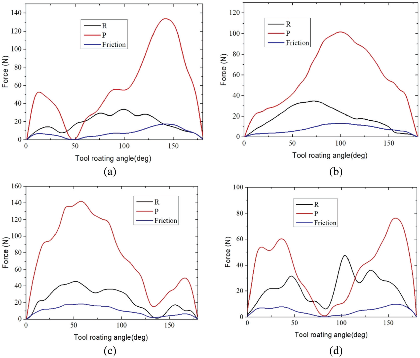
R, P, and friction of unidirectional CFRP: (a) Ψ = 0°, (b) Ψ = 45°, (c) Ψ = 90°, and (d) Ψ = 135°.
Table 2 shows the range of tool rotation angle and fiber cutting angle when P is relatively high. It can be found that when the CFRP ply angle is 0°, 45° and 90°, the corresponding fiber cutting angle when P is larger is around 150°. Because when the fiber layup angle is 135° and the fiber cutting angle is about 150°, the corresponding uncut chip thickness is very small. The larger area of P is that the fiber cutting angle is 155°–175° and 105°–125°. This is similar to the results gotten by He et al. 14 The possible reason for this phenomenon is that when the fiber cutting angle is about 150°, the movement direction of the cutter teeth is close to the direction of the fiber, and the fiber is easily squeezed under the cutter and cannot be cut. Therefore, the squeezing effect of fibers on the cutter in this area increases.
Tool rotation angle and fiber cutting angle corresponding to the larger area of P.

Figure 15 shows the damage of CFRP slot milling in four fiber layering methods (af = 0.1 mm/tooth, n = 4000 rpm, ap = 4 mm). By comparing Table 2 and Figure 15, it is found that the area with larger P value is the area where burrs and tears exist. It can be seen from the Coulomb friction law that the friction force and P have the same changing trend, so it can be concluded that the material damage is caused by excessive pressure and friction.
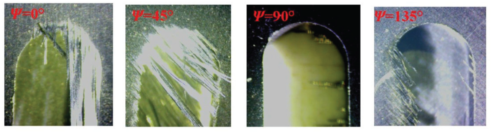
Unidirectional CFRP laminate slot milling damage.
Conclusion
The prediction model of the unidirectional CFRP laminate milling force considering the cutting edge force was established. Experiments show that the accuracy of the milling force prediction model considering the cutting edge force is higher than that of ignoring the cutting edge force.
The unidirectional CFRP laminate milling force model was successfully extended to the multi-directional CFRP laminate milling force prediction by superposition theory. Experiments prove that the predicted results are in good agreement with the experimental results.
When the CFRP layup angle are 0°, 45° and 90°, the corresponding fiber cutting angle when P is larger is around 150°. When the CFRP layer angle is 135°, the larger area of P is the fiber cutting angle of 155°–175° and 105°–125°. The cause of material damage is P and friction, and the CFRP damage in the area with larger P and friction is more serious.
Footnotes
Handling editor: James Baldwin
Declaration of conflicting interests
The author(s) declared no potential conflicts of interest with respect to the research, authorship, and/or publication of this article.
Funding
The author(s) disclosed receipt of the following financial support for the research, authorship, and/or publication of this article: This research was funded by Key R&D Project of Sichuan Provincial Department of Science and Technology, grant number 19ZDZX0055.