
Abstract
The expansion of preform and the optimization of preform have become important steps in the molding process. At present, there are some questions in the expansion of thermoset composite material preform and precompression, for example, the inaccurate dimensions, cracks, and wrinkles. For the expansion of preform, the finite element inverse algorithm is used as the expansion algorithm, and then the initial solution is optimized by the arc length mapping method, the expansion of preform is realized by the iterative equation which is solved by the ABAQUS solver. The effectiveness of the expansion of preform is verified through the comparison between the finite element inverse algorithm with DYNAFORM. The optimization of the precompression process is researched in order to solved the problems of cracks and wrinkles in the integral precompression method of preform. Firstly, the precompression sequence is adjusted by the precompression method, and then the precompression direction is optimized by the genetic algorithm. Through numerical simulation, the maximum thinning rate is reduced to 13%, and the maximum thickening rate is reduced to 6%, which improve the problems of cracks and wrinkles of preform, and the effectiveness of the optimization method is verified.
Keywords
Introduction
In the molding process, the quality of composite products can be improved by preforming the prepreg and then molding. First of all, the prepreg needs to be expanded into a certain shape of blank before preforming, the phenomenon of crack, and wrinkle during preforming can be reduced by the reasonable blank shape, as well as the trimming workload will be reduced after molding. 1 Then, in order to improve product quality and improve product production efficiency, the prepreg is pressed into a certain shape through preforming. The quality of preform will be affected by the factors such as the direction of precompression when preforming.
The blank expand method of preform could be divided into two types: the geometric method and the mechanical method. In the geometric method, the geometric relationship between the expanded shape and the preform was only considered. The common geometric methods are: analytical method, surface parameterization method, ABF method, discrete Gaussian curvature to parameterize the surface, Gaussian curvature, and geodesic principle combined, complex surface development based on mesh edges, etc.2,3 The influence of the constitutive equation of the stress-strain relationship of the prepreg on the expansion of the blank was not considered in the geometric method, and the result does not match the actual situation exactly. In the mechanical method, the constitutive equation of the raw material is applied to the blank expansion. Kim et al. 4 proposed a rigid-plastic finite element method based on the variational principle to calculate the relationship between stress and strain at each point. Yang et al. 5 combined with Kim’s idea and proposed an elastic-plastic finite element method, transformed the stress-strain matrix, derived the elastoplastic stress-strain matrix, and promoted the application and development of mechanical preform expansion. Liang and Bin 6 proposed a constrained nonlinear optimization method for the expansion of preform, but the global optimal results could not be got. Azariadis et al. 7 proposed an improved algorithm for the global optimization expansion of any blank surface, and the optimized expansion of preform was obtained by genetic algorithm. However, most of the current researches focus on the blank expansion of metal materials or thermoplastic prepreg, and the research on the blank expansion of thermoset composite prepreg is still very few.
The conventional method for solving the expansion of the preform is the finite element incremental method, but it has many preconditions and its use is restricted. The finite element inverse algorithm only considers the initial configuration and the final configuration, which increases the calculation speed. The inverse finite element algorithm requires an initial solution and iterative solution. At present, the vertical projection method and the spherical projection method are often used to determine the initial solution. However, the projection area will be zero when the projection point is not selected properly during the calculation in these two methods which determine the initial solution, and the effective solution can be obtained.
The preform is got through the precompression of multi-layer prepreg after blank expansion. The process of precompression can be divided into single-process precompression, compound mold precompression and continuous mold precompression. The traditional precompression design mainly relies on the designer’s experience, various precompression parameters are modified repeatedly, and it is time-consuming, high-cost, and difficult to adapt to the requirements of modern industry. 8 At present, many researches have been carried out on the forming law of preforming during precompression, and numerical simulation has been used in the field of molding widely.
First of all, the thickness and wrinkles of the preform were affected by the pressure and temperature of preform. Ivanov and Lomov 9 calculated the law of prepreg thickness change with pressure from the perspective of mechanics, and explained the thickness deformation mechanism of prepreg during compression. Ho et al. 10 reduced forming defects through improving the mold and considering the mechanical properties of laminated composite materials with different thicknesses. Somashekar et al. 11 researched the characteristics of the compression and rebound of glass fiber preforms, and found that the rebound characteristics of preform were related to the maximum pressure, the rebound thickness was unchanged when the pressure exceeds the critical value. Sun et al. 12 found that the generation of wrinkles in laminates was related to the friction mechanism closely, and the friction mechanism could be changed by increasing the preforming pressure.
Furthermore, the relationship between the layup sequence of the prepreg and the mechanical properties of the preform was studied. Wang et al. 13 simulated and analyzed the tensile properties of several preforms with different layup orders by using finite element theory, and found that the influence of the layup order on the rigidity of the preform. Lee et al. 14 evaluated the effect of different stacking sequences of prepregs on mechanical properties, then the validation of bending stiffness prediction model was performed by comparing the load per stress roller stroke through three-point bending analysis and test.
In addition, the cause of the defect was clarified by analyzing the interlayer change mechanism of the precompression prepreg through the numerical simulation of preforming. Wang et al. 15 analyzed the in-plane shear behavior of thermoset prepregs during preforming, and proposed that the relationship between stress and strain would change under different preforming speeds. Wang et al.16,17 studied the interfacial behavior between prepreg laminates, and established a finite element model of prepreg preforming which considered the effects of preforming pressure, then the preforming experiments of the prepreg laminates were implemented and simulated by using the proposed FE mode, comparisons between experimental results and simulation data verified the numerical model. Boisse et al. 18 proposed the second gradient method to describe the generation of wrinkles based on the research of slippage phenomenon in the preforming process of prepreg, and simulated it with meso finite element models used for macroscopic forming. Zhang et al. 19 established a interaction model through the research of influence of the precompression direction on the interaction between different prepreg laminates during prepreg preforming, and proposed a comprehensive computational material engineering method, then the preforming process was simulated from the micro and macro perspectives.
Different preforming processes and optimization of process parameters have been studied, and the preforming winkles, mechanical properties and other indicators have been improved. Sorrentino and Bellini 20 researched the hot drape forming process for preforming, which improved the wrinkles and irregular thickness. Kim et al. 21 evaluated the effect of different molding conditions on the mechanical properties of composite materials, and the optimized molding process parameters were obtained after experimental comparison. Di et al. 22 proposed that the maximum initial contact area was the main criterion for establishing the precompression direction based on the grid data of the cover, and established the algorithm model with the direction vector as a variable, then developed the corresponding module which could determine the precompression direction quickly.
However, there are many analyses on the preforming mechanism in the preforming process of prepregs, and there are few applied researches on the process optimization methods of the preforming process, especially the multi-objective optimization of prepreg preforming quality has not been studied.
In this paper, firstly, a finite element analysis model for composite material prepreg expansion is established. The mechanical expansion method based on the constitutive equation of the prepreg is used, combined with the inverse finite element algorithm to solve the equation, and then the arc length mapping method is used to optimize the initial solution which is obtained by the vertical projection method, and the numerical simulation of the composite material prepreg expansion is carried out. The effectiveness of the finite element inverse algorithm for composite material prepreg deployment is verified through theoretical analysis, numerical simulation, and comparison. Then, after the expansion of preform, multiple precompression regions of the preform will be selected, the precompression direction is used as the process parameter, the overall thinning rate of the multiple regions is used as the optimization target, and the genetic algorithm is used to optimize the precompression direction, the effectiveness of the optimization results are verified by the simulation.
Materials and methods
Materials
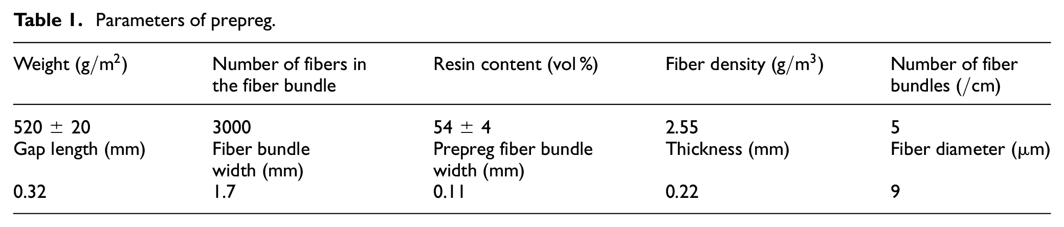
In this paper, glass fiber/epoxy resin prepreg is used to research, some structural parameters of the prepreg is shown in Table 1, including some parameters are provided by Taian Joy Composite Material Technology Co., Ltd., Taian, China.
Parameters of prepreg.
Mathematical model of expansion
The basic principle of the finite element inverse algorithm
Lee and Huh 23 proposed the finite element inverse algorithm. Assuming that the preform process of the blank is loaded proportionally, the initial shape and final configuration of the blank are considered only, and the intermediate deformation process is not considered. Figure 1 is a schematic diagram of the finite element inverse algorithm.

Schematic diagram of finite element inverse algorithm.
In Figure 1, the blank A0 becomes the final configuration A under the action of the mold force, and the final configuration A is discretized triangularly. The position B0 of the node B in the blank A0 is obtained by the finite element method, and B is the final configuration at any point on the above, the initial blank shape of the preform and the thickness distribution after precompression can be obtained by comparing B and B0.
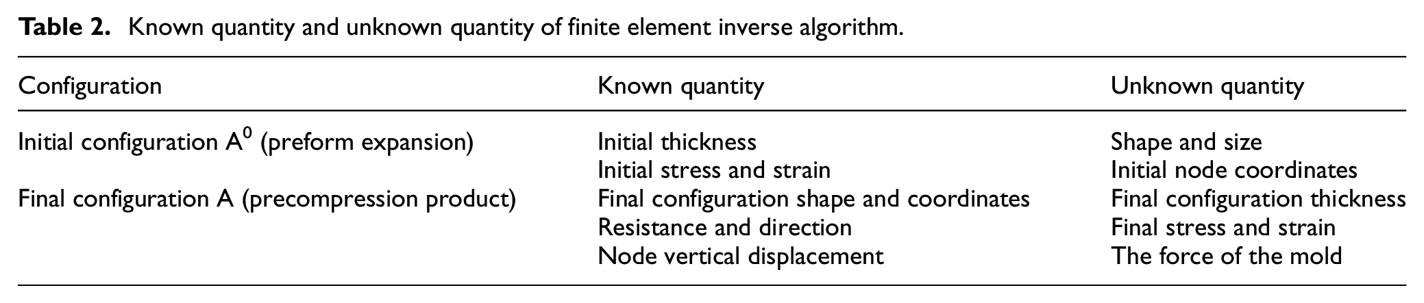
The configuration shape of the precompression product and the initial thickness of the blank are known conditions, and the geometric shape of the preform deployment and the thickness distribution of the final configuration are obtained. Through the known conditions and using the plastic work equation to obtain the unknown conditions, the desired geometry of the preform expansion can be obtained. The known and unknown quantities in the finite element inverse algorithm are shown in Table 2.
Known quantity and unknown quantity of finite element inverse algorithm.
The equation of the finite element inverse algorithm
Blank motion description and strain equation
When t = 0, the configuration where the object is not deformed or does not move is the initial configuration. When t > 0, it is called the current configuration. In the theoretical research, the Lagrange coordinate system (Matter coordinate system) can be introduced to determine the position of the initial configuration. In order to specifically express a point in the initial configuration, it is represented by X(
As shown in Figure 2, the Lagrange coordinate system is combined with the Euler coordinate system, and the current configuration is obtained from the initial configuration through a certain time t.
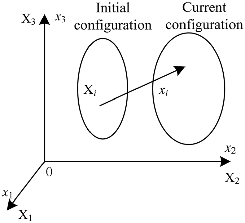
Two configurations at t = 0 and t > 0.
Combining the nodes in the graph with time t, the expressions of positions

The displacement of the node which is required to move from the initial configuration to the current configuration,

In the initial configuration, there are two nodes

The distance between the two nodes in the current configuration,

The Taylor series expansion at

The matrix
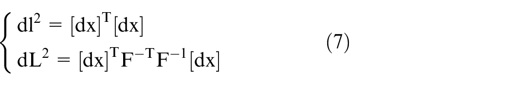
The Lagrange coordinate system is taken as an independent variable, from equation (5), the lengths of line elements,

The right Cauchy-Green deformation tensor is defined as
The Euler coordinate system is taken as the independent variable, from equation (5), the lengths of the line elements,
The left Cauchy-Green deformation tensor is defined as
Assuming that any amount of deformation in the current configuration is expressed as elongation

From equation (8),

In the preforming process of the blank, strain is introduced to describe the deformation of the blank. The final configuration is discretized into multiple triangular cells by using triangular unit cells. The complex equations of the entire region can be estimated by the deformation analysis of the triangular cells. As shown in Figure 3, each unit belonging to the final configuration is mapped to the initial configuration unit. The strain of the entire element can be obtained by calculating the amount

Element mapping from final state to initial state.
The equation for obtaining unit strain is known as:

Let

Constitutive relationship
The constitutive relationship represents the relation between stress and strain. In this paper, the epoxy glass fiber prepreg is used for preforming. It can be expressed as:

Where

In this constitutive equation (12), there are six parameters,
In this paper, epoxy resin,

For coupling viscosities

Minimum plastic work and iterative equation
Chung and Richmond 26 combined the deformation theory with the extreme value work path and proposed the ideal deformation. The ideal deformation can be applied to the process of the preform and the finite element inverse algorithm program will be developed. Considering the deformation process as a uniform speed process, the incompressible condition of plastic deformation is also considered, the plastic work of uneven deformation is expressed as:
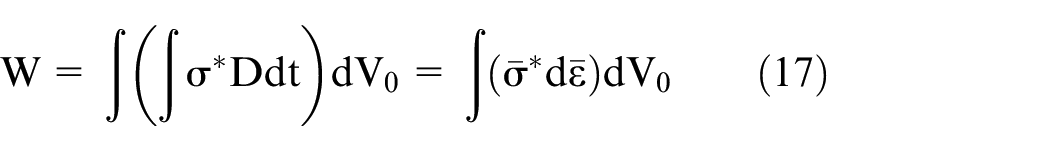
Here,

And the relationship between the coordinates of the initial configuration and the final configuration is:

Here,

Here,

In the equation (21),
Initial solution and optimization
The nonlinear equation (21) is difficult to solve directly, so it is necessary to give an initial estimate
The initial solution
Lee and Huh 23 proposed to use linear mapping to map the final configuration to the initial plane, and then obtained the initial solution in the finite element inverse algorithm. However, the vertical projection method is used in the linear mapping method, which will affect the correctness of the initial solution and the solution of the inverse algorithm in special cases. Figure 4 is a schematic diagram of the vertical projection method.

Schematic diagram of vertical projection.
The principle of the vertical projection method is used to project the discrete nodes in the final configuration vertically onto the initial plane along the precompression direction, so the initial solution can be obtained. There are many problems in practical applications. When a part of the element is
The optimization of initial solution
In order to solve the above problems, the arc length mapping method is used to optimize the initial solution in this paper. The arc length mapping method can avoid the situation where the projected area of the element is zero, and improve the accuracy of the result. And the initial solution is calculated by the arc length mapping method is closer to the result obtained by the inverse algorithm, which can accelerate the convergence speed of the inverse algorithm. As shown in Figure 5.
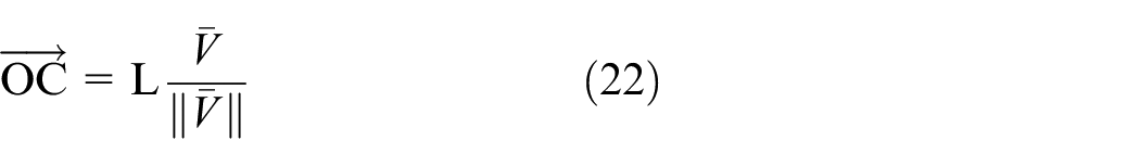
(1) O is the expansion center point, A is the selected starting point, B is the selected current node, the section perpendicular to the X–Y plane formed by the two points is P, and the arc length between the section and the final configuration is L.
(2) The projection of the section on the X–Y plane is supposed as
(3) Transform point B into all the nodes of the final configuration, and traverse all the nodes to get the initial calculate value

Schematic diagram of arc length mapping method.
The solution can be solved by the Newton-Raphson method iteratively after obtaining the initial solution
The optimization of precompression direction
For the expansion prepreg, the integral precompression process is used firstly, then the step-by-step precompression method is used to change the precompression sequence, and the precompression direction is optimized by genetic algorithm to improve the preform quality.
Evaluation function
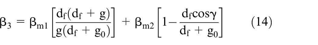
The angle

Section analysis schematic diagram.
The initial contact area as:
The uniformity of the distribution of initial contact points as:

The degree of dispersion of the initial contact points as:

The uniformity of precompression resistance as:

Where
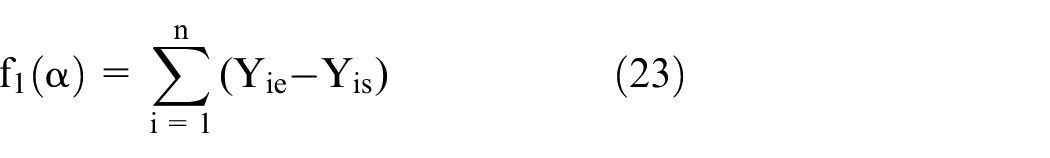
The evaluation function method can be used to transform multi-objective optimization problems into single-objective optimization. The evaluation function U(α) can be expressed as:

Genetic algorithm optimization
There is a nonlinear relationship between the thinning rate of each region and the direction of precompression. In this paper, the genetic algorithm is used to optimize the direction of precompression, and to find the global optimum of the thinning rate of each region.
During the operation of the genetic algorithm, the feasible solutions are operated to achieve the purpose of optimization. The process is shown as in Figure 7.

Genetic algorithm workflow.
Coding
The z axis is taked as the reference direction, the decision variables are the rotation angle
Fitness
The value range of the function is always non-negative, and that the maximum value of the function can be solved is the optimization goal. Therefore, this paper takes the individual fitness directly as the corresponding evaluation function value.
Choose
The proportional selection operator is selected in operation.
Crossover
The single-point crossover operator is used in crossover operation. In each generation group, the number of individuals performing the crossover operation is determined by the crossover probability. Here, this parameter is defined as a constant.
Variation
The basic bit mutation operator is used in mutation operation. The probability of mutation here is defined as a constant.
The generation of the next generation group is generated after the three operations of selection, crossover and mutation for the individuals of the previous generation group. In addition, the situation of each generation of individuals is output, including the genotype and phenotype of each generation of individuals, the value of the evaluation function, the average value of the evaluation function of each generation, and the current optimal value. Then, the optimization of the stamping direction is completed finally.
Results and discussion
This section may be divided by subheadings. It should provide a concise and precise description of the experimental results, their interpretation as well as the experimental conclusions that can be drawn.
Expansion of battery box preform
Expansion of the finite element inverse algorithm
The battery box of the electric car is selected as the object. The battery box is 1700 mm long, 1000 mm wide, and the highest part has a height of 300 mm. Discrete the triangular unit of the battery box CAD model, as shown in Figure 8, which contains 76,633 nodes and 23,834 units, Figure 9 is an expansion of the battery box model.

Discrete model of triangular element for battery box.

(a) Expansion diagram of the finite element inverse algorithm and (b) expansion diagram of DYNAFORM.
The initial solution is plugged into the solver for calculation, and that the blank shape of the product is get only takes 15 s. It can be seen that the optimized initial solution algorithm based on the arc length mapping method is suitable for finding the final solution of the finite element inverse algorithm. The expansion of the preform is shown in Figure 9(a). In order to verify the accuracy of the inverse algorithm, Figure 9(b) is the expansion diagram of DYNAFORM software.
Analysis of expansion calculation of battery box perform
For clear comparison, the size difference between the two expansion methods are compared, and the larger part of the difference for calculation is intercepted, as shown in Figure 10. Through calculation, it is found that compared with the calculation by DYNAFORM software, the expansion of the blank by the finite element inverse algorithm is in a compact state, with a maximum reduction of 10.2 mm, and the overall reduction of prepreg is 5.45%, which reduces the cutting workload of composite materials in the later period.

Shape comparison between finite element inverse algorithm and DYNAFORM.
Precompression process design
Integral precompression process
DYNAFORM is used to simulate the integral precompression process. The blank is a glass fiber epoxy prepreg with a thickness of 2 mm, a precompression of 2000 N, and a precompression direction of −Z. Figure 11 shows the thickness distribution after precompression.

Thickness distribution diagram of integral precompression preforming method.
It can be seen that the thickness of the three points A, B, and C is between 0.56 and 0.95 mm, with a thinning rate of 52.5% −72%, the phenomena of cracks are occurred. The thickness of the three points D, E, and F is between 2.3 and 2.4 mm, which indicates that the wrinkles are generated.
Step-By-Step precompression process
Division of precompression area
In view of the above problems, a Step-By-Step precompression process is proposed. Multiple precompression at different positions is performed on the same station and the same mold. The sequence of the precompression is shown in Figure 12.

Step-By-Step precompression sequence diagram.
There are 11 cylinders for precompression, and the Roman numerals are used to represent the precompression sequence:
I. Integral positioning and precompression.
II. Two-wing positioning precompression.
III.IV. The most severe part of cracks.
V. VI. The most severe part of wrinkles.
Optimization of solution
According to the genetic algorithm, the solution of precompression direction optimization can be got. The precompression sequence I and II do not need to change the precompression direction, it is still −Z direction, the precompression sequence of the precompression sequence III and IV is (±
Verification of simulation
Through the Step-by-step method, the precompression direction of some areas are changed, the remaining conditions remain unchanged, and the thickness distribution map of the simulated stepwise precompression is obtained, as shown in Figure 13.

Thickness distribution of Step-By-Step preforming after optimizing the direction.
From Figure 13, we can find that the preforming effect is better. The thickness of the H part is 1.74–1.92 mm, and the thinning effect is reduced obviously. The thinning rate is 4% −13%, which is a normal thinning situation. The thickness of the G part is between 2.05–2.12 mm, and the wrinkling is also slowed down significantly.
Conclusions
In order to solve the problem of the inaccurate dimensions of preform, the principle of blank expansion is analyzed in this paper, and the finite element inverse algorithm is used to expand the blank of preform according to the constitutive relationship of the thermoset composite prepreg, then a typical composite material is selected. The battery box is taken as an example, and it is realized by ABAQUS programming, and then compared with DYNAFORM, the expansion shape of the inverse finite element algorithm is more accurate, and the amount of prepreg can be reduced by 5.45%. Aiming at the problems of cracks and wrinkles in the preform during the integral precompression, the preform of the battery box is divided into 11 areas in this paper, and the Step-By-Step precompression method is used for preforming. Then, the evaluation function is established according to the precompression direction of different areas, and the precompression direction is optimized by the genetic algorithm, the optimal angle of the precompression direction is obtained in different regions. In the numerical simulation, the maximum thinning rate is reduced to 13%, and the maximum thickening rate is reduced to 6%, the cracks and wrinkles of the preform have been improved significantly.
Footnotes
Handling Editor: James Baldwin
Author contributions
Conceptualization and methodology, J.H., B.Y. and J.X.; software and validation, J.H., Q.H.; formal analysis and writing—original draft preparation, J.H., Q.H.; writing—review and editing, B.Y. and J.X.; All authors have read and agreed to the published version of the manuscript.
Declaration of conflicting interests
The author(s) declared no potential conflicts of interest with respect to the research, authorship, and/or publication of this article.
Funding
The author(s) disclosed receipt of the following financial support for the research, authorship, and/or publication of this article: This research was funded by National Key R&D Program of China, Grant/Award Number: 2017YFD060080204; Science and Technology R&D Program of Heilongjiang, Grant/Award Number: TSTAU-R2018002