
Abstract
Nondestructive test method for residual stress in a structural member is always an important research subject, as a new technique for measuring residual stress loading measuring method needs to consummate for the convenience of engineering. The paper proves that nondestructive test loading measuring method is effective and accurate when compared with the result from hole-drilling method. Taking the measurement of residual stress of injection-molded part in automotive lamp as example, the residual stresses in the surface of injection-molded parts of automotive lamp measured by the two methods are very close based on the two measuring results. It shows that loading measuring method, a new method is used to measure the residual stress, has enough accuracy and credibility when it is used to measure the residual stress of complicated injection-molded part. It provides a basis for popularization and application of loading measuring method in engineering. The paper discusses the basic principles of loading measuring method and detailed procedure of the measurement of residual stress by loading measuring method; it gives out some advices to reduce the test errors.
Introduction
Residual stress test technique development up to now, began from 1930s, there have been dozens of test methods. The hole-drilling method and layer-removed method are more mature and widely used as means of mechanical measuring method. Hole-drilling method proposed by Mathar, 1 first because the operation is simple and convenient, less damage to the member and high measurement accuracy, is a general semi nondestructive test method for measuring the surface residual stress for current engineering materials. American Society for Testing Materials (ASTM) has developed a test standard in 1981 2 based on it.
In recent years, many scholars have conducted in-depth research on the hole-drilling method. Cong 3 used the finite element analysis software ABAQUS to study the relationship between the release coefficient, drilling position and drilling depth, and obtained the corresponding fitting curve. By used of the finite element numerical model Zhao 4 simulated the distribution of stress and strain for two different conditions before and after drilling. In combination with the strain measurement mechanism, the optimum parameters such as hole diameter, hole depth, and the position of strain rosette were finally determined. Kim et al. 5 compared the numerical simulation with the experimental results and obtained the reliability of using the hole-drilling method to measure the residual stress of injection molded parts, especially on injection molded parts with complex shapes. Seifi and Salimi-Majd 6 analyzed the influence of the plasticity and mechanical properties of the material on the residual stress measured by the hole-drilling method. When the performance of the material is close to the ideal elastic-plasticity, the measurement error is relatively large. Using an appropriate correction coefficient can effectively reduce the measuring error. Sicot et al. 7 studied the influence of drilling depth, position of the strain rosette relative to the borehole center, and correction factor on the accuracy of the hole-drilling method. Lee et al. 8 used EDM drilling and high-speed drilling methods to measure the residual stress of the tool steel. The results showed that the two results were very close.
The procedure of layer-removed method is to remove material layer by layer through cutting or electrochemical corrosion, which leads to relax residual stress and strain, and the stresses of each layer of the member layer removing can be obtained by use mechanical or viscoelastic model to calculate the stress value and correction value after layer removing and measuring relaxing strain. 9 However, this test method is only suitable for flat-plate type members, and it cannot be measured using this method for injection moldings with complicated shapes.
The paper 10 proposed a new nondestructive test method of residual stress-loading measuring method, and gave the basic principle and steps of the method for measuring residual stress by an example.
In order to estimate accuracy of the loading measuring method, residual stress distribution in a member was obtained by the loading measuring and hole drilling methods in this study. Through the experiment residual stress distribution of automotive lampshade injection molded part with complicated geometry was measured by these two methods. To insure measuring precision the loading strategy was discussed.
Residual stress test method
The principle of loading method
Loading measuring method, 10 loading method for short, is based on the linear superposition principle. Its main procedure is applying specific loads in the area of the member existing residual stress. The residual stress in the member is superposed with a known loading stress field, known as simulation stress, and the superposition stress is measured by strain test.
Its kernel is to measure the superposition stress, known as experimental stress, by strain test at measuring points of the member undertaking specific loads, and calculate simulation stress at measuring points by CAE simulation analysis on the member undertaking the same restraint and loads, Residual stress is obtained by subtracting experimental stresses with simulation stresses at measuring points.
Obviously the advantage of this method is nondestructive, residual stress could be obtained without hole drilling or layer removing on member.
Measuring steps of loading method
The basic steps of measuring residual stress using loading method are as follows:
Based on the computer geometry model, simulation stresses on measuring points of the member are obtained under certain restraints and specific loads by use of CAE method.
By strain test experimental stresses on measuring points are obtained under the same restraints and loads with step (a).
Residual stresses on measuring points of the member are obtained by subtracting experimental stresses with simulation stresses on measuring points.
In Figure 1 can be observed a flow chart of the loading method. The kernel points of this method are applying reasonable restraints and loads, where loading way will influence reasonability of state of simulation stresses directly. The basic features of reasonable simulation stress are as follows:
The applied load must ensure that the deformation of the member is within the elastic range, so that the residual stress field of the member, denoted by
In order to ensure the measurement accuracy, the applied load should not be too small; otherwise the simulation stresses also will be small, and error of strain test and stress superposition will be large.

The flow chart of loading method.
The loading way involves the number of loads, the position of load point, and load size, so called the loading strategy. Obviously, the loading strategy has great influence on measuring precision, so step (a) is very important. Usually a cut-and-try method is used for the reasonable loading strategy. The following takes hole-drilling method as comparative reference to investigate loading method by use of injection molded parts of the lampshade as an example, and discusses the loading strategy.
Calculation formula
Strain test of the step (b) in the above section uses 45° strain rosette, which is composed of three strain gauges as shown in Figure 2. The experimental stress

Where ε0, ε45, ε90 are the strain values of the strain rosette in three different directions, ε0 is the strain measurement of the R1 strain gauge parallel to the x-axis, ε45 and ε90 are 45° and 90° to the x-axis, respectively. As shown in Figure 2, σ1 and σ2 are principal stresses, θ is the angle between σ1 and the x-axis. And E is elastic modulus, μ is passion ratio of the member.

Map of strain rosette and stress state at a point.
On the other hand, simulation stress is obtained in the global coordinates, denoted as

The main procedure of hole-drilling method is that it drills a small hole in the area of residual stress to release residual stress, and measures this release amount through the strain test to determine the residual stress.
As shown in Figure 2, there is residual stress in an area of an isotropic member, assuming that it’s maximum and minimum principal stresses are σ1 and σ2, respectively. A 45° strain rosette is pasted at measuring point, and a small hole is drilled at the center of the strain rosette to measure the release strain. The formula for calculating the residual stress is (3). 11

Where A and B are the release coefficients when the borehole is a through hole. 11

Here r is the distance between the center of the strain rosette (location of the drilling hole) and the midpoint of R1, and ‘a’ is the radius of the drilled hole. When blind holes are used, the release coefficients A and B need to be recalibrated.
In order to compare the experiment results between these two measuring methods, the stresses values of formula (3) need to be translated to the local coordinate systems R1R2R3 as shown in Figure 2. The formula (2) also is used for translation after replacing
Experiments for contrasting test
Geometric features
Injection molding is one of the main methods of polymer processing. Injection molding process and the shape of some injection molding products inevitably lead to residual stress in injection molded parts and affect their performance. Therefore, reducing residual stress of injection molded parts is one of the research focuses in the injection molding processing industry. 12
As shown in Figure 3, the object studied is a lampshade for injection molded parts. Most of the automotive lamp parts are produced using injection molding processes, such as lampshade. When laying for a time after the injection molding completed, the surface of the lampshade is prone to cracking, which affects the production yield of the lamp. The reason is that the residual stress in lampshade is too large, and the deformation or cracking of the injection molded part is caused by the release of the residual stress. 13

Model of lampshade.
The material of the lampshade is known as Polycarbonate (PC for short), with a modulus of elasticity of 2.5 × 10⁹ Pa and a Poisson’s ratio of 0.4. Since the maximum length of the lampshade is 517 mm, the maximum width is 240 mm, and the thickness is 2 mm, it can be studied as a thin-walled part. That is, the finite element loading model of the loading method can be used as a shell model, and via hole could be drilled when measuring the residual stress for the hole-drilling method.
Experiment with loading method
According to the experimental procedure given by the loading method, the first step is to obtain the simulation stress of the measuring points on the surface of the lampshade by simulation. So the geometry model is constructed for the lampshade as shown in Figure 3, and the measuring points and loading points are given out in the defect area existing residual stress on the surface of the lampshade. According to the observation of the lampshade, one defect area is on the front of the lampshade, the other on the side. These two areas are taken as the measuring areas, and measuring points are selected, front A1, A2, and A3, side A4, A5; for loading points, front B1, B2, side B3, B4, as shown in Figure 4. Here, the loading strategy is: the affected area of the loading point is within the defect area of the lampshade, that is, it includes the measuring points; and a pair of uniformly distributed load with a radius of 1.5 mm centered on the loading point is applied. In this way, the load stress in the area between the two loading points is relatively uniform, which helps to reduce the measurement error. 10

(a) Front measuring and load points and (b) side measuring and load points.
The constraining way of the member is studied, which is easy to fix the member in the loading experiment. Because the shape of the lampshade is an irregular surface, the degree of freedom needs to be restrained according to the specific shape in the experiment. Therefore, a special fixing device is designed for its specific shape to ensure the lampshade not moving during the loading experiment, as shown in Figure 5(a). Figure 5(a) shows the constraints corresponding to Figure 4(a), which are applied to the two sides of the lampshade. The length of one side is 200 mm, and their three degrees of freedom are completely constrained; the other side has two supporting points with an area of 5 mm × 6 mm. In this way, a static model with simple supported boundary constraints and uniform load at two loading points is established. It is used to measure the residual stress at the three measuring points on the front of the lampshade. Similarly, as shown in Figures 4(b) and 5(b), a similar static model is also established for measuring of the residual stress on the side.

(a) Front fixing device and (b) side fixing device.
Now a computer geometric model could be established for the member, impose the same constraints and loads as the actual member, that is, establish the same simulation model for the member as the actual loading state, and perform linear elastic finite element static analysis. For this example, two simulation models need to be established. The purpose of establishing the simulation model is to determine the size of the applied load so as to ensure that the stress at the measuring points is not only in linear elastic range, but also large enough to ensure that the stress superposition calculation is reasonable without loss of significant figure. Than the simulation stress of the member is calculated after determining the size of the applied loads. For the member of the lampshade, the determined load size is 40 N, and the simulation stresses at the measuring points under this load are obtained.
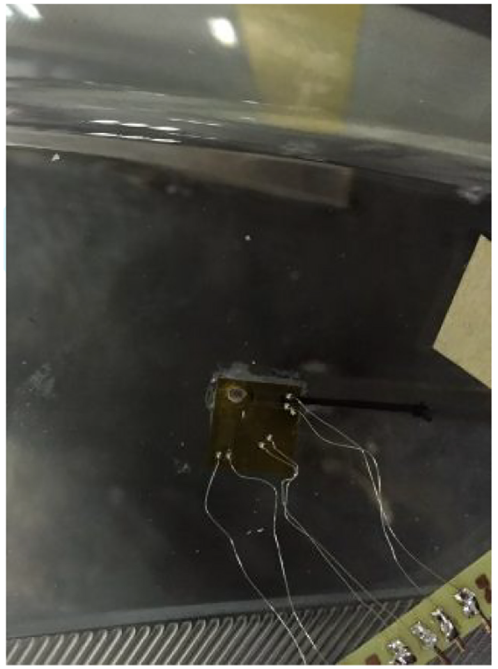
The second step is to complete the strain experiment. A 45° strain rosette are pasted at each measuring point, and the directions of R1 and R3 of the strain rosette are the X and Y axes of the point’s local coordinate system. Strain rosettes and strain gauges are connected by 1/4 bridge method. The temperature compensation adopts dynamic compensation method. That is, a temperature compensation sheet is attached to another identical part and is connected to the strain gauge, as shown in Figure 6.

Strain rosette wiring diagram.
Experiment with hole-drilling method
Two test members with the same injection molding process are used for the hole-drilling experiment. The diameter of drill bit used for drilling is 2.5 mm. A via hole is drilled in the measuring point in a direction perpendicular to the surface of the lampshade by using a pistol drill, as shown in Figure 7, and then the strain rate is recorded from the strain gauge, which is the stress release caused by drilling.
Hole drilling schematic diagram.
Experimental data processing for hole-drilling method
The first part of Table 1 shows the data measured by the hole-drilling method. As shown in Figure 2, the distance between the center of the strain rosette and the midpoint of R1 is 5 mm. According to the formula (3) and the data in Table 1, σ1 and σ2, the maximum and minimum residual stresses at each measuring point, can be obtained. In order to be able to compare with the results of the loading method, the residual stresses of each measuring point are converted to the local coordinate system of the measuring point. σx, σy, and τxy are obtained, as shown in the second part of Table 1.
The experimental data and analysis results.

Experiment data processing for loading method
The first part of Table 1 shows the experimental data obtained by the loading method and the hole-drilling method experiment. According to these experimental data, the residual stresses of the measuring point can be obtained using the corresponding calculation formula. The experimental data processing for the loading method is as follows.
First, the simulation stresses at measuring point obtained by the finite element analysis are converted to the local coordinate of the measuring point. The simulation stresses are represented in the global coordinate, and the experiment stresses obtained by the strain experiment are expressed in the local coordinate at each measuring point. Therefore, it is necessary to translate them to the same coordinate to perform the superposition operation. The paper performs the superposition operation using the transformation formula of stress tensor at local coordinate system of the measuring point. The simulation stresses σb given by finite element analysis of each measuring point are translated to local coordinate by formula (2).
Second it is to perform calculations for experiment stresses. According to the strain experimental data in the first part of Table 1, the experiment stresses σc in the local coordinates of each measuring point can be obtained by use of the formula (1) for the 45° strain rosette.
Last the residual stresses, σa, is obtained from the residual stress calculation formula, σa = σc-σb, as shown in the second part of Table 1.
The third part of Table 1 shows the results of comparative analysis of the residual stresses measured by the loading and drilling methods. It can be seen that the results obtained by the two methods are relatively close, which indicates that the residual stress measuring applied to the injection molded part by the loading method has sufficient accuracy and reliability.
From the experimental procedures of the loading method it can be seen that the following points are easy to cause measurement errors:
Differences between measuring points and loading points in the experiment, and measuring points and loading points in simulation calculation. In the simulation calculation it can accurately give out the coordinates of the measuring points and the loading points. However, in actual experiment, these points are determined manually and there are errors, especially for the members of injection molding part with curved surface shape.
The direction and size of the applied load in the experiment. Due to the manual applied load, there is a gap between the direction of the load and the direction required by the method. The load calculated by the simulation is a uniform load with a radius of 1.5 mm centered on the loading point, and it is difficult to ensure uniform distribution for the experimentally applied load.
Finite element simulation calculation error. This error has a certain influence on the precision of stress superposition.
Conclusion
This paper explores concrete steps of the loading method, a non-destructive test method, through a residual stresses measuring example for automotive lampshade injection molded parts, also discusses the measurement errors generated in each step of measuring process. The conclusions are as follows:
Through comparative analysis with the hole-drilling method it provides the basis for engineering application of the load method. The surface residual stresses of the lampshade measured by the two experimental methods are very close. It shows that the loading method has enough reliability and accuracy to measure the residual stress of complicated injection molded parts.
The loading strategy has great influence on measuring precision. On the premise of ensuring elastic deformation, loading should be as big as possible, and the stresses within certain range of measuring points should be as uniform as possible, which is benefit to reduce measuring errors.
Footnotes
Handling Editor: James Baldwin
Declaration of conflicting interests
The author(s) declared no potential conflicts of interest with respect to the research, authorship, and/or publication of this article.
Funding
The author(s) received no financial support for the research, authorship, and/or publication of this article.