
Abstract
In this study, the accuracy of blind-hole method on weld residual stress estimation is investigated. A modified parameter group has also proposed to improve the accuracy. The thermal-elastic-plastic finite element model is employed to build up the residual stress distribution and the blind-hole process. The MSC Marc finite element software package is used to simulate the welding process and the welding residual stress and strain distributions around the weld of two inconel 690 alloy plates filled with I-52 GTAW filler. Then the process of the traditional blind hole is simulated by employing the inactive elements. The data of the residual strain variations of strain gages located around the blind hole is introduced into the blind-hole method to estimate the original residual stress components at the hole center. The effects of drilling depth, drilling size, gage radius, gage position, and the distance on the accuracy of estimated residual stress have also been studied and discussed. Based on the residual stress components simulated from the welding process, a modified stress parameter group has also been proposed to improve the accuracy of blind-hole method. Numerical results indicate that the accuracy of estimated residual stress can be improved significantly by employing the proposed blind-hole parameters.
Keywords
Introduction
The hole-drilling strain-gage method can be divided into through-hole drilling and blind-hole drilling (BHD) methods. The through-hole drilling method involves directly drilling holes through a workpiece and observing the elastic strain energy release. The BHD method involves drilling a hole to a depth comparable with the hole size. Because the BHD method only generates local fractures, and the small hole drilled typically does not affect the normal usage of mechanical objects, the BHD method has been widely applied in industrial practice.
During an actual strain measurement process, measuring precise strain values is difficult and requires multiple measurements, hole-drilling method is the most to be used. 1 To employ the advanced computational capacity and enhanced software functions of computers, a finite element software package MSC Marc was employed to generate a residual stress field in a simulated engineering processing procedure. Subsequently, the BHD method was applied to determine the strain value around the hole and theoretically calculate the residual stress. On the basis of the simulation results, applicability of the BHD method was identified. The effect on the result of BHD parameters, such as changes in hole depth, distance from the welding bead center, initial position of the strain gage, gage radius ratio, and hole radius, was observed. A numerical analysis was applied to compare the BHD parameters, and the results were referenced to develop a more accurate method to measure residual stress.
P Gomes 2 presents the results of the residual strain and the stainless steel AISI 304. Steinzig 3 showed that accurate results can be achieved without ultra-high drill-rotation speed in aluminum and stainless steel. MR Viotti 4 found the influence of the feed and rotational speed on the hole walls, and the bottoms were evaluated for A36 steel and AISI 304L stainless steel.
BHD theory
This study explored the use of finite element software to simulate the residual stress generated on metal plates following heating and condensation. In addition, the deactivation software function was applied to remove BHD element simulation to estimate residual stress.
Theory
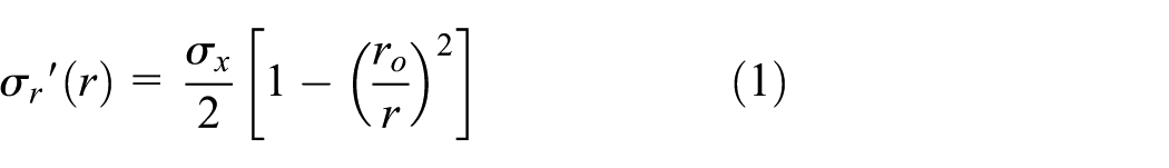
Because a hole with a radius of ro on an infinite plane slab is affected by a tensile plane stress, the stress state around the hole, according to elasticity explanation, 5 can be considered as superposition of Case 1 and Case 2, also shown respectively in Figure 1(a) and (b). The stress distribution in Case 1 can be expressed as follows


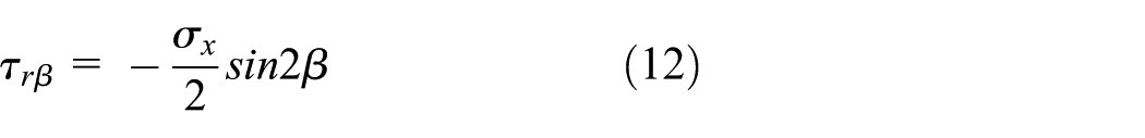
The stress distribution in Case 2 can be expressed as follows


where
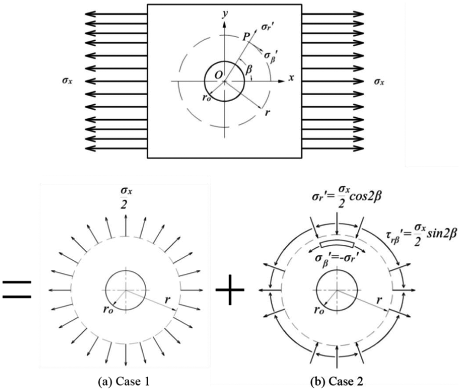
Circumferential stress around the hole of a drilled infinite plane slab affected by a tensile plane stress.


The stress of drilling point


Comparing the stress of the point


Substituting equations (7) and (10) into equation (13) results to equation (15)

Substituting equations (8) and (11) into equation (14) results to equation (16)

According to Kabiri,
6
the radial strain change is substantially greater than the circumferential strain change. When

Substituting equations (15) and (16) into equation (17) gives equation (18)


Equation (21) shows that three unknown values


Solving the simultaneous equations of (22), (23), and (24) yields the following equations


During the deduction process, the angle is given a positive sign when it is in a clockwise direction. Thus, when a commonly used principal stress coordinate relationship is integrated into equation (27), the positive sign is instead given to the counterclockwise direction.
In reality, BHD experiments are conducted on slabs with a finite width and the measured strain value is the average strain value of the area covered by the strain gage, instead of a point. Rendler and Vigness
7
asserted that the theory of the through-hole drilling method is applicable to the BHD method. However, the A and B coefficients in equations (19) and (20) must be corrected to calibration coefficients

BHD parameter setting
Figure 2 shows the geometric parameters and relevant sign definition required for estimating residual stress based on the BHD method. The initial position of the first strain gage is

Geometric parameters.
Heat source setting
For heat source, scholars used TEM00 modal in the past. The highest laser power density concentrates on the center, gradually decreases with increasing radius, formed Gaussian distribution, so it is also called Gaussian laser. TEM00 laser power density as followed

where

where s is standard deviation. Define Re is the radius of spot size, 95% power covered the scope


Substituting equation (33) into (32) forms equation (34)

In 1984, Goldak et al. 10 based on two dimensions Gaussian heat source proposed a double-ellipsoidal Gaussian heat source model. Model is divided by electric arc center as shown in Figure 3, the model of x, y, z distribution power decrease by Gaussian function.
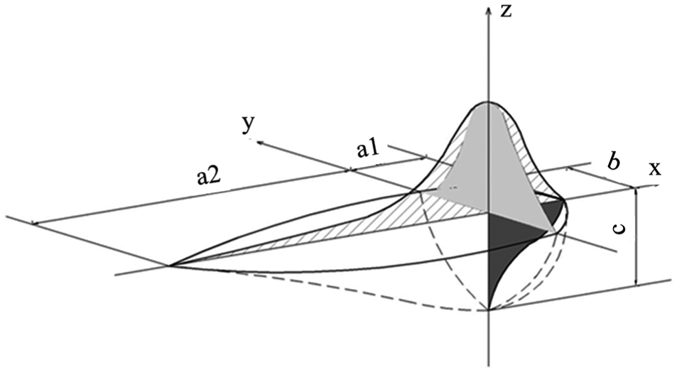
Double-ellipsoidal heat model.
Finite analysis by double-ellipsoidal Gaussian heat source presented not only the bath during arc welding short-former long-latter, but also the heat source distribution of depth.
Double-ellipsoidal Gaussian heat source model have two part functions, function of former half is

and function of latter half is

where ηw is the welding heat efficiency, I is the welding current, and V is the electric arc voltage.
Finite element model
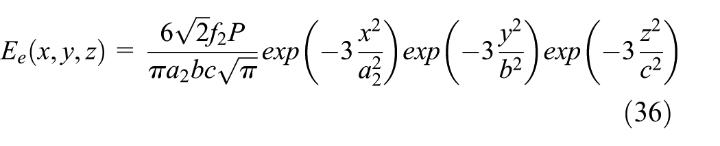
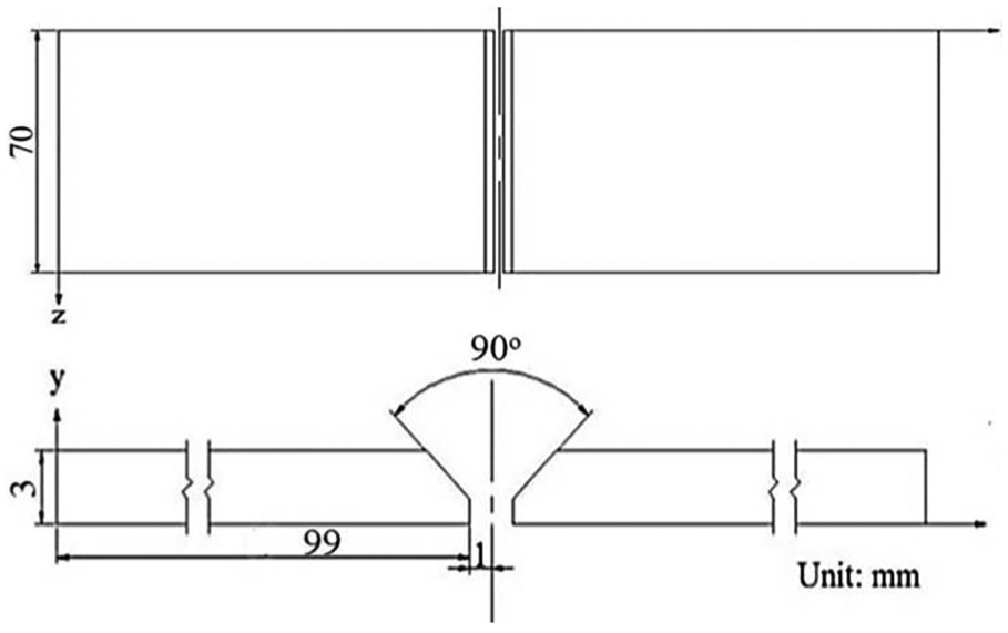
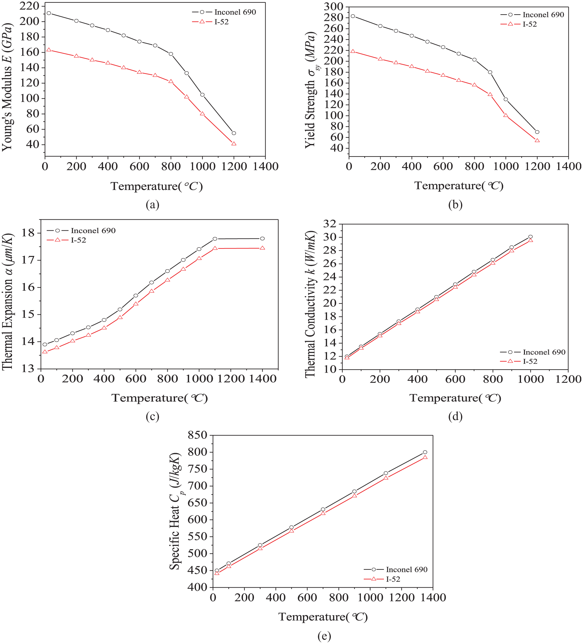
In accordance with Lee, 11 two metal plates of inconel alloy 690 of 100-mm length, 70-mm width, and 3-mm thickness were welded using V Groove butt welding, included angle 90°, bottom gap 2 mm, distance from bottom 1 mm. A finite element model was established with the dimensions depicted in Figure 4. Solder used INCONEL Filler Metal 52 (I-52) for welding. I-52 has better melting flow, resists pyrolysis and solidification crack ability. The alloy composition is similar to inconel alloy 690. 12 The distance between each hole center and welding bead central line is listed in Table 1. Thermomechanical coupling was applied to reduce the consumption of calculation resources. A semi-symmetric model was applied for the analysis, as shown in Figure 5. The material properties of Inconel alloy 690 and I-52 are shown in Figure 6. The simulated boundary conditions of welding thermal residual stress were set as follows.
Dimensions of welded metal plate.
Distance between hole center and welding bead central line.


Diagram of element cutting.
During the welding process, the environment temperature was set as 20°C and the solder melting point was 1350°C. At the first welding bead, the welding velocity, welding bead length, and welding bead height were 1.4 mm/s, 70 mm, and 2 mm respectively. At the second welding bead, the welding velocity, welding bead length, and welding bead height were 1.8 mm/s, 70 mm, and 1.6 mm, respectively. The two plane slabs dissipated heat through natural convection as the temperature reduced to room temperature. In the geometric shape of the proposed model, the convection coefficient was set as 13.5 W/(m2 K). The deactivation element command of the applied software program was employed to remove blind-hole elements to attain the re-equilibrium of the residual stress field.
Non-dimensional coefficient correction
In accordance with the theory and simulation steps described in previous sections, this section investigates the difference between the residual stress field of metal plate welding obtained in a finite element simulation and the residual stress field estimated using the American society for Testing and Materials (ASTM) E 837-01 norms. The least squares error method was applied to correct the coefficients proposed by the norms.
Figures 7 and 8 show the values estimated using ASTM norms at the position, respectively. The estimated values could not simultaneously satisfy individual optimal precisions.

ASTM-based estimation of

ASTM-based estimation of
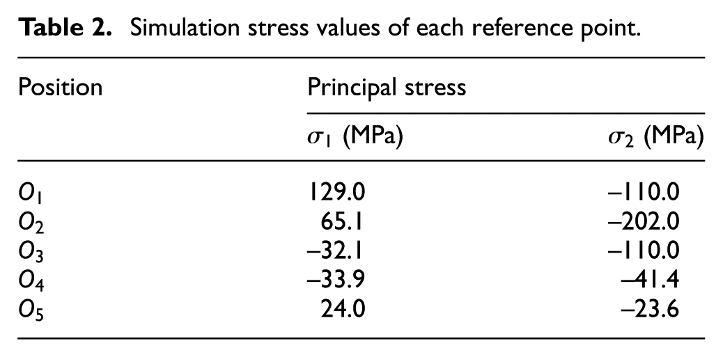
Thus, the least square error method was applied to correct the non-dimensional coefficients proposed by ASTM norms, thereby determining the non-dimensional parameters that improve the estimation accuracy. The stress of each reference point calculated using the finite element method is depicted in Table 2. The domains of parameter changes are tabulated in Table 3.
Simulation stress values of each reference point.
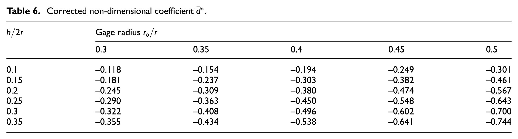
Corrected non-dimensional coefficient

The correction coefficients


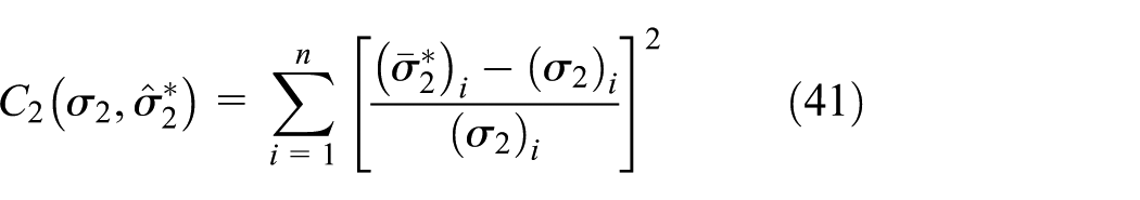
Substituting equations (38) and (39) into equations (25) and (26) and defining the objective function

A partial derivative of the regression coefficients
Corrected non-dimensional coefficient

The resulting
Corrected non-dimensional coefficient

Corrected non-dimensional coefficient
Parameter discussion
The results of corrected ASTM non-dimensional coefficients show that the corrected non-dimensional coefficients do not necessarily generate more accurate results in all conditions than ASTM coefficients. Thus, all parameters were included for discussion. Moreover, the optimal condition to use corrected non-dimensional parameters in BHD testing was proposed to achieve accurate estimation of the welding residual stress.
The reference value of each parameter was set as follows: hole depth = 0.25 mm, distance from the welding bead center = 12 mm, strain-gage angle = 0°, hole radius = 1 mm, and gage radius = 0.4 mm. The domains of parameter changes were 0.1–0.55 mm for the hole depth, 5.62–15 mm for the distance from the welding bead center, 0°–
The parameters and the domains of their changes are tabulated in Table 7. To investigate the blind-hole depth, the reference points with different distances from the welding bead center mentioned in the preceding two sections were applied for an analysis. In each analysis, one parameter, such as distance, strain-gage angle, hole radius, or gage radius, was changed, while the other parameters remained as the reference values. The accuracy of the analysis results were compared with those yielded from using the ASTM E 837-01 norms.
Parameter setting.

Figure 9 shows the relationship between the stress percentage error at each reference point and the hole depth. At the reference point with a distance of 20 mm from the welding bead center, the estimation error was considerably higher than it was at other positions; thus, the distance of 20 mm was not included as a recommended domain. With 0.25 and 0.4 mm hole depths, the
Relationship between the corrected estimation stress and welding bead center position.
As shown in Figure 9, corrected coefficients were also applied to estimate
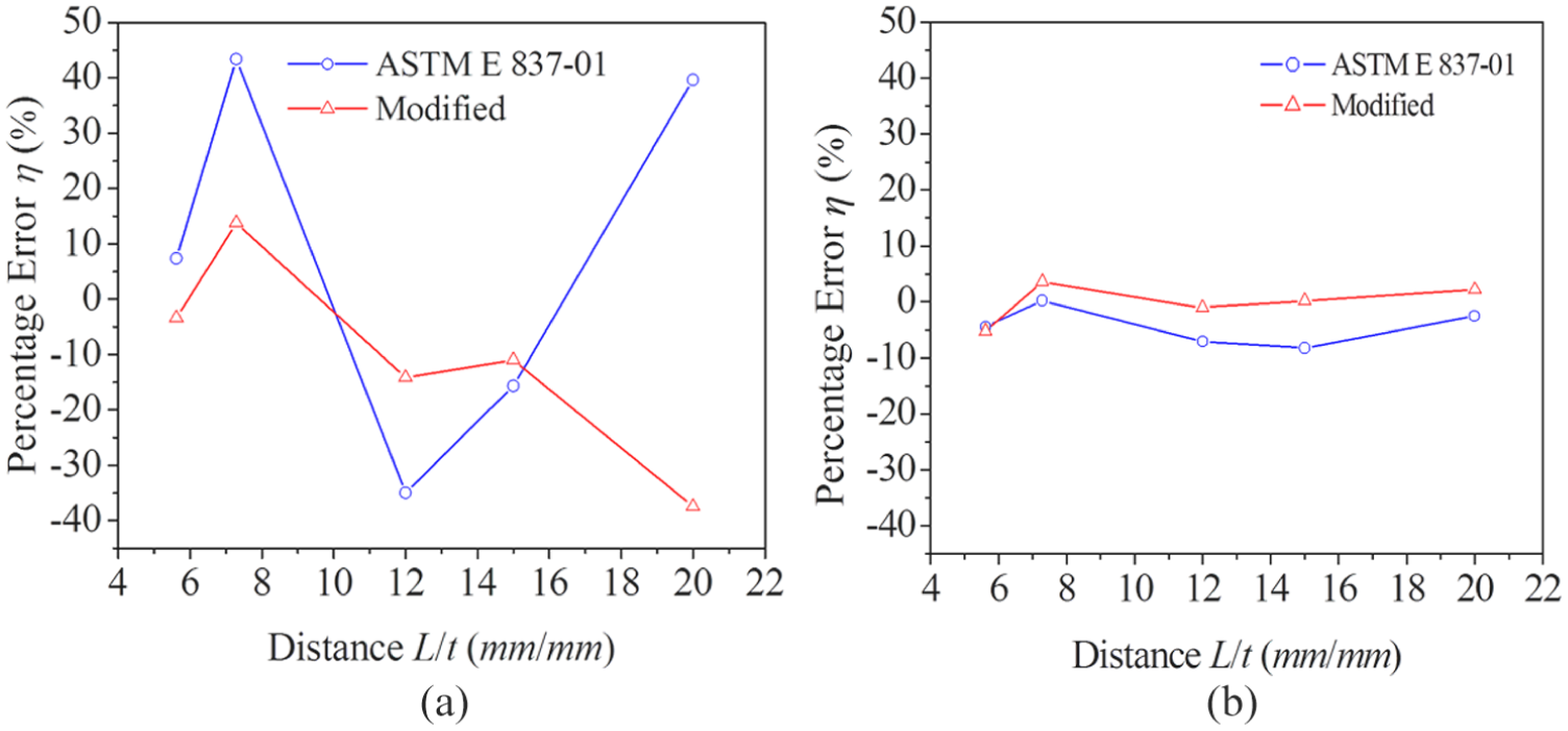
The stress estimation errors based on the corrected coefficients and radial strain changes of different initial strain-gage angles were compared with the ASTM norm estimation errors, as depicted in Figure 10, As shown in Figure 10(a), which depicts the

Relationship between the corrected estimation stress and the strain-gage angle: (a) σ1 and (b) σ2.
These results indicate that estimating welding residual stress by using corrected coefficients at different strain-gage angles and distances from the welding bead center can limit the estimation error within 15%. Compared with the estimation results yielded using ASTM norms, the corrected coefficients effectively improve the accuracy of the BHD method in estimating the residual stress in welding.
Figure 11 depicts the comparison between accuracies of hole radii estimated using the corrected coefficients and ASTM norm coefficients. In estimation of

Relationship between the corrected estimation stress and hole radius. (a) σ1 and (b) σ2.
Figure 12 depicts an accuracy comparison of gage radius ratios between the corrected and ASTM norm estimation results. When the hole radius was 1 mm, the gage radius ratio had little effect on estimation accuracy. After the gage radius ratio increased from 0.33 to 0.5 mm, the

Relationship between corrected estimation stress and gage radius ratios. (a) σ1 and (b) σ2.
The analysis results showed that to lower the fracture level on the specimen while maintaining estimation accuracy, the hole radius should be selected from a range between 0.5 and 1 mm. In accordance with the recommended hole radius range, the optimal domain for the gage radius ratio was 0.4 mm. Finally, the recommended domains of the parameters, such as hole depth, distance from the welding bead center, initial strain-gage angle, hole radius, and gage radius ratio are tabulated in Table 8.
Recommended domain for each parameter.

Conclusion
A finite element analysis model for simulating and analyzing the welding-induced residual stress field and BHD applications was proposed in this study. By comparing the estimation of principal stress and the finite element results, combined with applying the least squares error method, new non-dimensional coefficients were developed. The recommended domains for each parameter in this study revealed that the proposed calculation methods generated more accurate results than did the ASTM E 837-01 norms.
A finite element analysis model for simulating and analyzing the welding-induced residual stress field and BHD applications was proposed in this study.
The study also used the blind-hole specification which provides the dimensionless coefficients
Measurement of residual stress, there are significant impact stress-affected zone on the results, including distance, blind-hole depth, pore size, and location parameters such as strain gage.
A new dimensionless coefficients
Footnotes
Handling Editor: Stephen D Prior
Declaration of conflicting interests
The author(s) declared no potential conflicts of interest with respect to the research, authorship, and/or publication of this article.
Funding
The author(s) received no financial support for the research, authorship, and/or publication of this article.