
Abstract
Interference-fit is attracting increasing attention in the aerospace field because of its excellent enhancement of the sealing and fatigue life of carbon fiber reinforced plastic (CFRP). However, it also induces imbalanced pre-tightening forces on the interface, and affects its mechanical behavior. A series of experiments were conducted to assess the imbalanced pre-tightening force of CFRP interference bolted joints and its effects. High-precision washer force sensors were used to measure the pre-tightening force between upper and lower surfaces at various interference-fit and torque. Strain gauges were used to estimate the varying effect on the imbalanced pre-tightening force during tensile tests. The effects of varying interference-fit and torque on pre-loaded transfer, surface strain distribution, tensile strength, and damage mode were identified. The results show that the synergy of interference-fit and torque induces an imbalanced pre-tightening force, which, in turn, changes the stress-strain evolution of the surface, and a special “transition regime” was identified in the evolution curves. Compared with clearance-fit, the ultimate strength and optimal torque of interference-fit joints could be significantly enhanced. In addition, the damage originates from fiber/matrix slipping to the upper surface with a low pre-tightening force and the formation of stack buckling, which then causes delamination fracture.
Keywords
Introduction
In the field of mechanical engineering, interference fit and bolt pre-tightening force (caused by tightening torque) are widely used to improve the performance of structure-connecting.1–3 Because of the development of the aviation engineering technology, in aircrafts of the new types, interference fit is gradually applied to composites connecting structures. However, bolted connections still remain the main connecting method of composites during aircraft assembly. The literature shows that both interference-fit and bolt pre-tightening force can significantly improve the performance of composites bolted joints.4–6 However, because of the low interlaminar strength and weak properties of composite, it was concluded that the pre-tightening force should be restrained along the thickness direction.7,8 In addition, the interference fit can also micro-damage the connection hole,9–11 which causes premature failure.
Few reports addressed the combined effect of interference fit and pre-tightening force on composite joints. A number of researchers focused on the effect of interference fit in CFRP. Kim and Kim 12 investigated the effect of interference-fit on the bearing strength and fatigue life of pin-loaded CFRP laminate, and found that interference-fit improved the joint stiffness, bearing strength, and fatigue life. Wei et al. 6 investigated the effect of the interference fit on bearing and fatigue life of CFRP joints, and found that appropriate interference fit size significantly improved the strength of the structure. At the same time, a number of experimental studies identified the reasons why clearance should be avoided during the composites connecting.13–15 These experiments demonstrated that the effective connection area increased with increasing clearance, and the contact compressive stress showed a sharp increase. Another group of researchers focuses on the pre-tightening force (i.e. the nut tightening and forming preload before service load) during the assemble process of a threaded fastener.16,17 Cooper and Turvey, 18 Park 19 and Sun et al.20,21 investigated the benefits and mechanism of the connection strength of the individual parts of composites. Based on experiments and finite element analysis, they found that the pre-tightening force played an importance role in improving the strength of bolted structures. Other researchers analyzed the comprehensive impact of the interference associated torque for CFRP joints. Zhang et al. 22 identified the optimal interference-fit and torque by combing experimental and numerical methods; however, the research did not consider the impact of the preload imbalance. Hu et al.23,24 investigated the mechanism of bolt pre-tightening and preload relaxation in composite interference-fit joint structures, and identified a frictional force. This force resulted in a difference between clamping forces at two sides of the fastener. However, Hu focused on the impacts of the installation process and second bending on the resulting damage. These researchers focused on the interference-fit that causes micro-damage around the hole and tried to improve the mechanical strength (i.e. the universal torque was mainly used, which was obtained from the clearance-fit, which differs from the optical torque used in this paper). However, the fact that interference-fit will cause friction loss and interface imbalance and the underlying causative effect has received little attention. This will lead to differences in bolted joint load-bearing behavior and damage initiation.
In a bolted joint with clearance fit, the pre-tightening force, caused by tightening torque at the nut end is the same as nail-head end along the thickness direction of the joint. However, in an interference-fit type connecting structure, a state of mutual restraint exists between the bolt shank and the connection hole, when an oversized fastener is squeezed into the connection hole. The pre-tightening force at the nail-head end will be lower than at the nut end, because of the friction between the bolt shank and the wall of the hole. This inconsistency of pre-tightening forces at the two ends influences the bearing phenomenon. At present, research on the imbalance of pre-tightening force is limited, and the combined effect of interference fit and tightening torque on the bearing of bolted composite joints has attracted little attention.
In this paper, high-precision dynamometers at both ends of the connector were set up to obtain relevant data of the interface pre-tightening force. The imbalance of pre-tightening forces between nut end and nail-head end are analyzed, and a mathematical equation of the difference value of pre-tightening force is established. Furthermore, by analyzing the stress-strain around the hole and the microscopic morphology of the damaged area, the effects of an imbalanced pre-tightening force on the properties of this mechanism are investigated. The findings reported here provided guidance for the design and development of CFRP interference bolted joints with excellent mechanical properties. Moreover, this paper also provides data support for the modification of finite element models.
Experimental process
Materials
The utilized composite laminates were manufactured from a carbon fiber/epoxy material (T700SC/3660) and the lay-ups were set up in quasi-isotropic stacking sequence [0/45/90/-45]6s. A thickness of 0.15 mm per ply (provided by the Aerospace Science and Technology Corporation, China) and the 20-ply CFRP provide a thickness of 3 mm with a fiber volume fraction of 65%. Ti alloy Hi-Lok bolts were made with Ti-6Al-4V.
To obtain CFRP interference connected specimens, Hi-Lok bolts of standard size were installed into undersized holes. Hole diameters of CFRP with several sizes were designed, so that various interference fit conditions could be generated. Each specimen consists of two CFRP sheets with identical hole diameter. To ensure the hole diameters of the upper and lower CFRP sheet are consistent and accurate, a set of special coating four-flute, triple angle dagger drill tools (the predecessor of Xiamen Tungsten Co., Ltd, China) for CFRP drilling were used () and H4-tolerance reamers were applied to test the diameters.
The interference-fit percentage can be calculated by the equation:

where D represents the diameter of the bolt and d represents the hole diameter of the specimen.
Multi-surfaces pre-tightening force test
Each diameter of titanium Hi-Lok bolt (M6) was measured to ensure accuracy of the interference-fit size. This study tested the following four groups of hole diameter values: 0.14%, 0.54%, 1.25%, and 2.24%.
A high-precision washer force sensor (Kistler SlimLine Sensors 9133B, Switzerland) with an inner diameter of 6.1 mm and an outer diameter of 16 mm was used to test the pre-tightening force. A charge amplifier (Kistler 5073, Switzerland) and a transient signal recorder (HBM G2Ni, China) were used to record the data. A professional-grade adjustable torque wrench (SATA 962118, USA) was used to change the tightening torque.
The sensors were calibrated before each test, and Figure 1 shows the complete test process of pre-tightening force. A steel washer and a force sensor were placed between nail-head and CFRP sheet. The interference fit bolt was pushed into the hole, using a universal testing machine (MTS Criterion 64.305), at a speed of 1.5 mm/min, until the lower surface of the nail-head reached the sensor. Then, force sensor #2 was placed between the lower sheet and the steel gasket, while the nut was screwed up using a torque wrench.

Schematic diagram of pre-tightening force measurement.
As shown in Figure 1, the pre-tightening forces on the upper surface (nail-head end) and lower surface (nut end) were measured by two groups of force sensors. The tightening torque gradually increased from 1 to10 N·m.
Mechanical test
To analyze the effect of tightening force and interference-fit size on the structure strength of CFRP joints, tensile strength tests were carried out. Figure 2 shows the geometric dimensions of the specimen, which was used, according to the ASTM D5961 standard test method, to determine the bearing strength of single-lap CFRP bolted joints. Considering the specimen length and buckling of joints, during the loading, gaskets with the same thickness as CFRP sheet were adhered to the CFRP sheets, using 302 modified acrylate resin agent in the gripping area (76 mm length).

Geometry of the tensile specimen.
An Orthogonal experiment was used to demonstrate the effect of interference-fit size and torque on the tensile mechanical properties. Four groups of interference fit sizes (0%, 0.54%, 1.25%, and 2.24%) and four groups of tightening torques (Finger tight, 3, 6, and 9 N·m) were tested, respectively. Table 1 lists the interference fit and tightening torque values of the specimen groups. The tensile test was carried out using a universal testing machine (MTS Criterion 64.305) at a speed of 1.5 mm/min at room temperature. At least three tensile samples for each CFRP bolted joint were tested, to derive average values. It should be pointed out that, during the actual experimental process, because of the manual effort alone, the pre-tightening force did likely not exceed 25 N at the lower surface (the upper surface was lower for interference-fit joint). This is a far lower than applied in other torque conditions.
Interference fit sizes and tightening torques for tensile specimen groups.

As shown in Table 2, Strain gauges or digital image correlation (DIC) system are commonly used to analyze the mechanical behavior of CFRP structural members. The researchers mainly focus on structure deformation caused by hole wall deformation, so they use embedded strain gauges (e.g. in the shank or on the surface of the shank) or DIC to analyze the deformation of the joints. Considering the imbalance pre-tightening forces of the upper and lower surfaces would affect the mechanical behavior of both surfaces (upper and lower surface), two groups of strain gauges (Each group consists of five strain gauges) were settled up at a completely symmetrical position for simultaneous analysis of its mechanical behavior in this paper. To investigate the effects of imbalance on mechanical, the strains around the connection hole were measured during the tensile tests. Figure 2 depicts the positions of strain gauges. The strain gauges have been placed at symmetrical positions, between the upper and lower surface.
Typical mechanical behavior test methods for composite bolted joints.

The bearing stress, σbr, was calculated as follows:
where, Pb represents the bolt load, D represents the Hi-Lok bolt diameter, and h represents the laminate thickness.
Results and discussion
Pre-tightening force transfer
Bolt-tightening torque can induce a pre-tightening force between sheets. The pre-tightening forces and the typical pre-tightening force versus tightening torque curves are illustrated in Figure 3, at four groups of interference fit levels. The force sensor #1 measures the pre-tightening force at the upper surface and the force sensor #2 measures data for the lower surface. The pre-tightening force at the lower surface exceeded that at the upper surface, because of the friction between bolt shank and hole side wall. The curve evolution is associated with both the hole diameter and the interference fit.

Pre-tightening force with different interference fit values under various tightening torque values.
According to the data depicted in Figure 3, the pre-tightening force at the lower surface increases linearly. The regarding the pre-tightening force on the upper surface is slightly lower than on the lower surfaces, when the interference fit size is small. However, the difference becomes obvious when the interference fit exceeds 1.25%. The pre-tightening force on the upper surface increases slowly when the tightening torque is low (e.g. 1 or 2 N·m), especially in case of a large interference fit size. The pre-tightening force does not provide adequate preload to offset the friction between bolt shank and hole side wall. At low tightening torque is low, the pre-tightening force on the upper surface did not change significantly (the value was almost 0), while the regime with stable value will increase with increasing interference fit size.
A contact area under pressure will form between bolt shank and hole side wall, during the installation. The friction force, caused by squeezing, will affect the transfer of the pre-tightening force between upper and lower surfaces. Figure 4 shows the pre-tightening force difference, between upper and lower surfaces. The deviation was not constant, and increased rapidly at first then declined slowly with increasing tightening torque, and finally converged to a constant value. The maximum difference values range between 3 and 6 N·m (the higher the tightening torque, the higher the peak). The effect of the tightening torque can be divided into one part regarding the offsetting of friction and second part regarding the formation of pre-tightening force on the upper surface. Thereby, the pre-tightening force on the upper surface occurs when it exceeds the max-static friction value. It should be noted that, the difference decreases when it reaches the peak. This may occur because of stress release and surface damage of the CFRP hole. 9 The difference will converge to a constant value (i.e. the tightening torque reaches 8 N·m, in this paper) which can be considered as friction between bolt shank and hole side wall.

Deviation between the pre-tightening forces of upper and lower surfaces: (a) deviation at various interference fit and tightening force values and (b) fitting curve of peak value.
Figure 4(a) shows that, the influence of interference fit on the transfer of pre-tightening force for CFRP bolted joint is significant. On a gap-fit bolted joint for composites, the torque of Ti alloy Hi-Lok was set to 2.24 N·m. The nut will screw out when the torque exceeds the design value. Both the difference and friction force increase with increasing interference fit size. As the size of interference fit increases, a needs higher tightening torque value is needed to reach the peak of the difference. For example, the peak occurs at 3 N·m when interference fit is 0.14%, while the peak occurs at 6 N·m when interference fit is 2.24%. In addition, the hole diameter also affects the transfer of the pre-tightening force. Both the difference and friction force increase, as the hole diameter increases as a result of the increasing contact area. Therefore, to obtain a suitable preload, the torque usually needs to be higher in case of interference fit.
Figure 4(b) illustrates the fitting curve of the peak deviation value for the pre-tightening force between upper and lower surface, at various interference-fit sizes. Both the deviation and the interference-fit size can be approximated by linear fitting, the results of which indicate that the friction force on the surface is proportional to the interface pressing force. However, considering that fiber-resin is a brittle material, the fiber will bend or may even break during the interference fit installation process (in cases where the amount of interference is large), while the resin will be worn or fractured, and debris may migrate out of the contact surface. When the amount of interference further increases, layering occurs, 8 and the actual interface characteristics are complicated. Compared with the actual data, a cubic fitting equation is more accurate, and can be formulated as follows:

where, Pd represents the maximum deviation value between the upper and lower surfaces and i represents the amount of interference.
Surface S-S distribution and evolution
Interference fit and pre-tightening force can change the stress-strain distribution around the contact area, which will inevitably affect the strain, during the tensile process. Figure 5 shows a typical strain curve during the tensile test at various interference-fit sizes and tightening torque values. When interference fit size is 0% and torque varies (as shown in Figure 5(a) and (b)), the strain evolution at the upper and lower surfaces is almost identical; however, if the tightening torque is 0 N·m and the interference fit size varies (in Figure 5(a) and (c)), the strain evolution is identical at both upper and lower surfaces. The deviation of strain curves at various interference fit sizes and torque values, appears in areas #2 and #4, where it increases rapidly at the late stage of the tensile test. As shown in Figure 5(d) (where both interference fit and torque are applied), the strain deviation value becomes even more obvious. In general, both interference fit and tightening torque will change the shape of the strain curve on an interference fit bolted joint, while they will also cause strain deviations between upper and lower surfaces.

Typical strain-t curve for various interference-fit sizes and tightening torque values: (a) Interference-fit size 0%, Torque 0 N·m, (b) Interference-fit size 0%, Torque 9N·m, (c) Interference-fit size 1.25%, Torque 0N·m and (d) Interference-fit size 1.25%, Torque 9N·m.
Both interference fit and pre-tightening force can affect strain evolution, resulting in various curves. Figure 6(a) and (b) show the effects of interference fit and tightening torque, respectively, on strain in area #1. As the interference fit size increases, the strain of the CFRP bolt joint decreases (Figure 6(a)). In an interference fit joint, the contact area around the hole will subject to pressure, as the interference fit size increases, thus improving the stiffness. Therefore, at the same load, the strain will decrease in response to increasing interference-fit size; however, for the same applied load, a higher tightening torque decreases the strain, as shown in Figure 6(b). In other words, as the same strain is generated near the circumference, the greater the applied torque, the greater the required load. In addition, the strain value increases smoothly at a tightening torque of 0 N·m, while it steeply increases during a certain period of time after the application of the tightening torque. The existence of tightening torque leads to a rapid increase of the strain rate at the later stage of tension, while it postpones deformation of the hole. It is worth noting that within a certain range, a larger torque will generate a more obvious effect; when the torsion reaches a certain threshold value, the effect weakens. Figure 6(b) shows that the torques at 6 and 9 N·m are similar.

The effects of interference-fit size and torque on strain at #1: (a) non-torque and (b) non-interference.
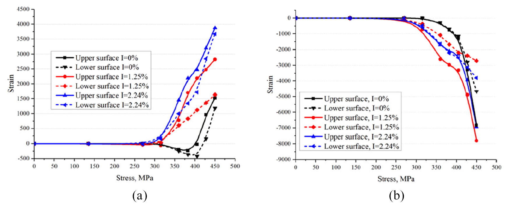
When both tightening torque and interference are simultaneously applied to the joints, the surface strain changes. The stress-strain distribution on the upper and lower surfaces differs. Figure 7 shows the stress-strain curve under different interference-fit sizes at a torque of 6 N·m. Figure 7(a) shows the upper surface (i.e. the nail-head end) at area #1, while Figure 7(b) illustrates the lower surface (i.e. the nut end) at area #5 (symmetrical position of #1). As shown in Figure 7, there is a significant difference between the upper and the lower surface strain evolutions, during the tensile process. The surface strains of both upper and lower parts are almost identical in the non-interference joints, while the value of strain curvature decreases with increasing amount of interference. However, the strain curves of the upper surface display a “transition regime” in the interference-fit joints. As the load increases, the strain increases slowly in the transition regime, while as the interference-fit size increases, the strain value of transition regime is increasing. With regard to the strain of the lower surface, the strain evolution process remains similar when the interference-fit sizes are 1.25% and 2.24%, while the slopes are different, as shown in Figure 7. Compared with the upper and lower surfaces of non-interference joints, the state is imbalanced. This may be due to differences in pre-tightening forces, generated by the upper and lower surfaces, as well as due to differences in the residual stress distribution on the surfaces of the hole. Therefore, there is also a difference in the strengthening effect around the hole area. Application of the tensile load causes a different performance regarding the stress-strain evolution between upper and lower surfaces.

Strains of upper and lower surfaces at a torque of 6 Nm at #1 and #5: (a) upper surface and (b) lower surface.
In addition, the interference joint exhibits compressive strain earlier than the non-interference joint. The interference fit generates a tight hole-wall contact, while the hole side wall is subjected to a pressing force. When external load is applied, it will be directly transmitted to the hole side wall, while the non-interference joint represents a clearance-fit case. When the external load is low, it is first offset by friction. Therefore, the interference joint demonstrates compressive strain first. It should be noted that, the slope of the compressive strain on the interference member is less than that on the non-interference member. This is because the interference fit can enhance the strength of the joint, while the actual contact area, caused by the interference, exceeds that generated by non-interference. This means that the actual compressive strength is lower than in the non-interference case.
According to Hu et al., who use optical strain gauges to study composite tensile specimens 26 and a theoretical calculation model of Wu et al., 27 for the tensile behavior of interference joints, it can be determined that, except for area #1 (#5) with the highest axial strain, areas #3 (#7), and #4 (#8) will be subject to high axial and tangential stresses. Therefore, an experimental study of the stress-strain behavior of these two regions was also carried out, while the upper surface regions #3 and #4 as well as the lower surface regions #7 and #8, at symmetrical positions, are compared and analyzed. A comparison of Figure 8(a) and (b) shows that the deviation value of the upper and lower surface strains increases first and then decreases, in response to increasing interference-fit size, under the effects of interference and tightening torque. There are two reasons for this occurrence. On the one hand, this may be due to an increased amount of interference, resulting in increased friction between the shank and hole surface, as well as the formation of a buffer intermediate layer caused by bucking of the fiber. As the amount of interference further increases, the actual pre-tightening force is smaller. This is because the increase of interference size causes an increase in frictional force, and thus the offset pre-tightening force also increases. As a result, the effect of pre-tightening force is weakened. On the other hand, damage caused by the applied pressure emerges near the CFRP hole side wall during tensile. The fiber-matrix is broken and the residual stress, as a result of fiber buckling, is released. 4
The strain of upper and lower surfaces at a torque of 3 N m: (a) in areas #3 and #7 and (b) in areas #4 and #8.
Tensile strength
Tightening torque and interference-fit size exert significant influences on tensile strength of CFRP bolt joints. Tensile tests were conducted according to Table 1, and the load-displacement curves are presented in Figure 9. It should be noted that, the pre-tightening force caused by finger tightening is very low (less than 25 N, as measured by the sensor), compared with other tightening torques. It is important to mention that, there is not phenomenonn of “2% offset bearing strength” in interference-fit CFRP joints. As shown in Figure 9(a)–(d), as the tightening torque and interference-fit values increase, the ultimate strength increases first and then declines.

Effect of tightening torque and interference-fit size on tensile strength: (a) interference fit 0%, (b) interference fit 0.54%, (c) interference fit 1.25%, and (d) interference fit 2.24%.
An appropriate level of tightening torque can improve the ultimate strength of CFRP bolted joints, clearly supported by different amounts of interference fit. First, pre-tightening force, caused by tightening torque along the sheet thickness direction, can cause friction between two sheets; specifically, the tangential friction component can share part of tensile loading. Second, “lateral support” will be provided because of tightening torque, thus reducing sub-bending, which improves the structural stiffness in the circumferential region of the connection hole. Third, the pre-tightening force can effectively reduce the delamination damage of the CFRP, reduce the formation of micro-cracks, and inhibit the expansion of already existing cracks. At the same time, the friction force, generated by the pre-tightening force on the contact surface, can guide the transmission of the applied load. This is significant to reduce stress concentration.
According to earlier research,10,28 although interference fit causes micro-damage on the hole side wall, the contribution of gain exceeds that of weakening, at an appropriate interference fit size. Consequently, a firm connection can form and the contact area increases, thus decreasing the related stress. Furthermore, the buckling fiber will play a buffer role, and slowing down both crack initiation and propagation. All these effects can improve the tensile performance; however, when the interference fit exceeds the optimal value, the strength will decrease, because of severe damage in the connection area.
Interference fit can affect the optimal torque of the bolted joint, while the tightening torque affects the structural strength. According to ASTM 5961, the appropriate tightening torque ranges within 2.2–3.4 N·m with a clearance fit. In this paper, the ultimate strength is reached when tightening torque is 3–6 N·m in all interference fits (Figure 9(e)). It is well known that for a bolt structural member (gap fit) that is mainly subjected to shear load, the interface friction force (upper and lower surface), because of the pre-tightening force, is its main bearing mode. The results of pre-tightening force transfer show that, because of interference fit, the friction between shank and hole side wall offsets part of the pre-tightening force. This results in an increased preload requirement.
As the tightening torque increases, the effect of the interference fit on the ultimate strength weakens. According to Figure 9(f), when the torque reaches 6 N·m, the difference between the maximum (I = 1.25%) and minimum (I = 0%) is only less than 20%. The optimal interference amount is 1.25%, in this paper and the torque is 6 N·m. It should be noted that, the interlaminar strength of CFRP is weak, which may lead to fiber fracture and matrix cracking, during tightening. Therefore, excessive tightening torque (2.24% in this paper) causes damage around the surface, especially the lower surface, which reduces the strength of the bolted joint.
In addition, because of the interaction between interference fit and pre-tightening force, the load-displacement curve of the interference-fit type bolted joint is differ from that of the clearance-fit type bolted joint. Figure 10 shows a typical L-D curve of CFRP interference fit bolted joint. Compared to clearance fit, 29 the curve of the transition phase increases linearly, because interference fit plays a key role in both the initial phase and the transition phase. The curve of the transition phase is horizontal for clearance fit bolted joint.

Typical L-D curve of CFRP interference fit bolted joints.
Because of the close contact between shank and hole side wall, both interference fit and pre-tightening force can increase the stiffness of the joint. During the initial phase, the slope value increases as the interference-fit size increases. In their study, McCarthy et al. 29 found that the “transition phase” of the clearance-fit bolted fasteners with high torque is horizontal. This occurs because, when the tensile load exceeds the maximum static friction, the static friction will be converted into sliding friction, thus causing the bolt-shank to slide. The tensile load is offset by the friction force, and the hole deformation is extremely small at this stage. However, the applied load of the interference-fit bolted joint still increases linearly at the transition phase, as it always presents a squeeze force.
Failure analysis
Figure 11 shows the tensile failure morphology of specimens. Failure mode occurs when the hole is stretched, followed by the lateral fracturing of layers. Figure 11(a) shows that, in the present study, the fracture is a squeeze fracture along 45°. The specific failure is similar to that described in earlier research, 8 which is mainly the compression-buckling-fracture-crushing of the CFRP, at the connection hole.
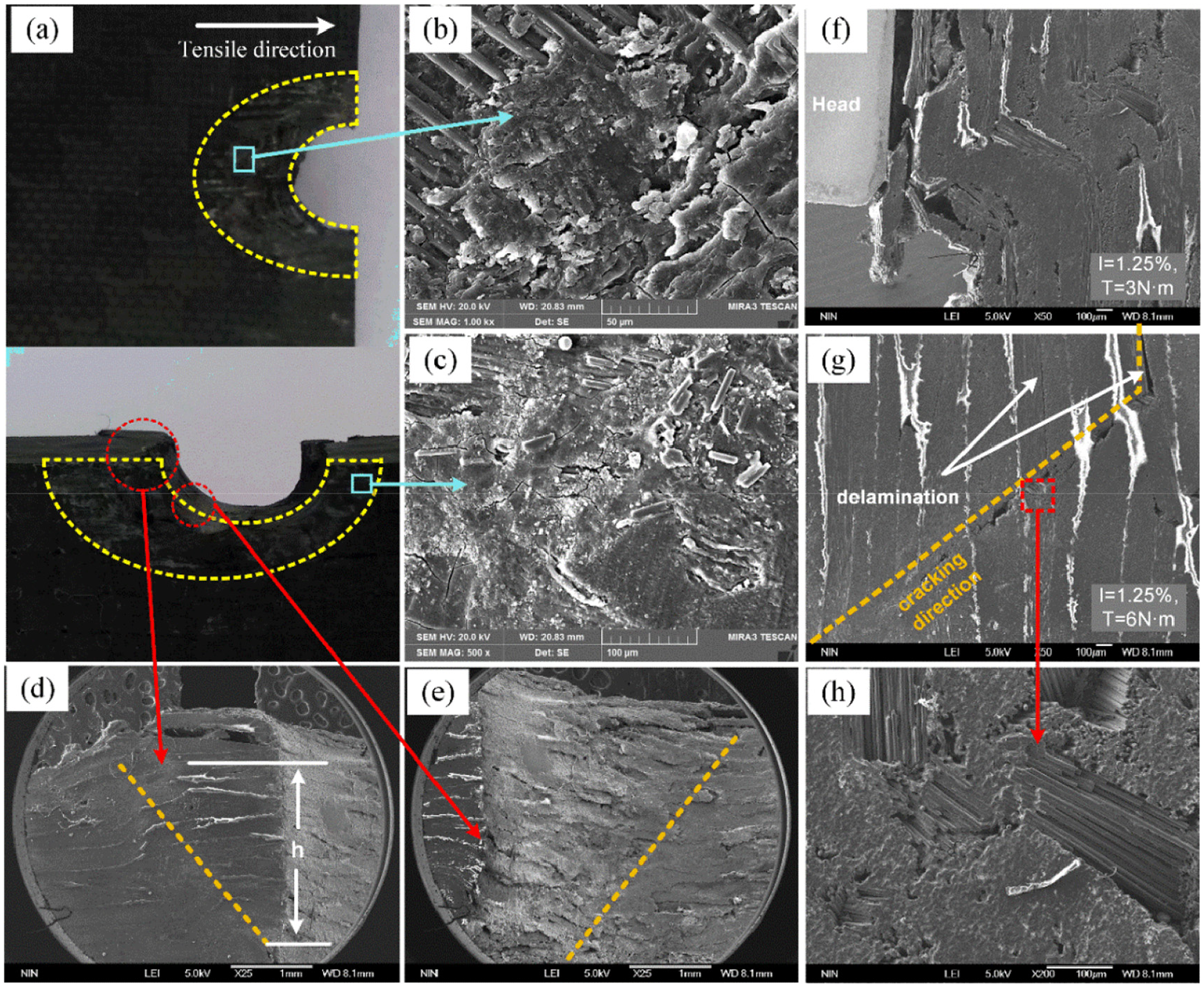
Tensile fracture morphology of specimens: (a) top view. Wear morphology at (b) and (c) the upper surface, (d), (e) around the hole, (f) the surface near the head of the bolt, and (g), (h) for cracking.
It should be noted that when the pre-tightening force is low, CFRP is prone to delamination damage, as shown in Figure 11(d)–(f), when it is inclined to the upper surface (lower pre-tightening force compared with the lower surface). Because of the smaller axial preload, the deformation on the side near the upper surface is larger, while even multiple breaks appear at the bolt-head side.
The tightening force plays a role in delamination inhibition. Specifically, when the tightening force is high, the deformation of the connection surface is limited, which prevents delamination. With increasing extrusion deformation, interlayer cracking occurs eventually, as illustrated in Figure 11(g). It should be noted that, unlike metal, CFRP is an anisotropic material with a significantly lower shear strength in the vertical direction than in the loading direction. If the tightening force is too high, the surface (especially the lower surface) will show microcracks and other damage will occur around the hole surface; however, an excessive tightening force will cause obvious wear on the surface of the structure, during the tensile process. As shown in Figure 11(b) and (c), the matrix will crack and peel off. When the matrix on the surface migrates, the exposed fiber will also fracture. Wear of the surface will accelerate this failure; therefore, when the tightening force is too high, the strength of the connection will be low.
Conclusion
The transfer of the pre-tightening force has been measured at various tightening torque values, at a CFRP interference-fit bolted joint. The effects of imbalance in the pre-tightening force on the upper and lower surfaces, caused by tightening torque and interference-fit size, on the stress-strain, ultimate strength, and failure during the tensile process have been investigated. The following conclusions could be drawn:
The interference fit leads to the imbalance of the pre-tightening force at the interlayer interface. The deviation of the pre-tightening force between upper and lower surface increases, with increasing interference-fit size. Larger tightening torque is required to reach the deviation peak, when the interference fit size increases. In addition, the difference transfer function and friction function between shank and hole side wall are presented.
The interference fit and the tightening torque affect the stress-strain evolution, both on the upper and lower surfaces. Because of the imbalance of the pre-tightening force, on the upper and lower surface, there is a “TR” region on the upper surface, which does not appear on the lower surface.
Tightening torque and interference fit can improve the mechanical properties of CFRP bolted joints. A higher tightening torque will cause a smaller effect of interference fit on the ultimate strength of the CFRP lap structure. An optimal value exists for the CFRP bolted joint, under the combined effects of tightening torque and interference fit. The highest ultimate strength is achieved at I = 1.25% and T = 3–6 N·m.
The imbalance of pre-tightening force can also affect the structural failure of the CFRP interference-fit bolted joint. Fiber-matrix compression failure and delamination damage are the main failure modes. The imbalance of the pre-tightening force also affects the deviation in the damaged area. Both the fracture surface and the stratified layer easily form at the lower pre-tightening force end, and the CFRP fragments between shank and hole also migrate there. Excessive tightening torque will also cause wear and micro-cracks on the surfaces, which affect the ultimate strength of the structure.
Footnotes
Handling Editor: James Baldwin
Declaration of conflicting interests
The author(s) declared no potential conflicts of interest with respect to the research, authorship, and/or publication of this article.
Funding
The author(s) disclosed receipt of the following financial support for the research, authorship, and/or publication of this article: The work reported is sponsored by the National Natural Science Foundation of China (11902135), Basic Research Project of Longyan Science and Technology Department (2018LYF8004), Open Project of PH. D research fund of Longyan University (LB2018019), and Young and Middle-aged Teacher Education and Research Project of Fujian Province (JAT190754), Guiding project of Fujian science and Technology Department (2019H0031).