
Abstract
When a large amount of heat is produced during the operation of a MRF (magnetorheological fluid) testing device, the temperature of the device will increase, which will in turn affect the characteristics of the MRF. Exploring the temperature field characteristics of the MRF yield stress testing device is necessary to improve the accuracy of the device. In this study, first, the yield stress testing device is designed, and then its temperature field model, including enameled wire and assembly gap, is established. Second, simulation software is used to simulate the temperature field change. Finally, a test platform is developed to test the simulation results, especially for two factors, namely, thermal conductivity of the coil winding and assembly gap, which demonstrate considerable influence. Comprehensive thermal conductivity and assembly clearance are determined, and the optimum temperature field of the device for measuring yield stress is resulted.
Keywords
Introduction
With the rapid development of modern science and technology, people are paying increasing attention to smart materials. Among these materials, magnetorheological fluid (MRF) is a kind of new intelligent material that can be controlled by a magnetic field and exhibits reversible stability by mixing magnetic particles with magnetization properties in a carrier liquid. Moreover, it has wide prospects and a high application value. MRF is a Newtonian fluid at zero field and a Bingham plastic fluid at non-zero field; thus, it has a reversible reaction rate of milliseconds and its viscosity can achieve continuous transformation. 1 The mass production and commercialization 2 of MRF and its application products in large companies, such as Lord 3 and Ford, 4 have begun. However, the research results of various countries regarding MRF still lack uniform standards, resulting in poor communication.
Many scientists have conducted series of research on the performance of the MRF testing device.5,6 In 1994, Ginder 7 used the finite element method to show that the maximum yield stress is proportional to the saturation magnetization of magnetic particles. The test results of Weiss 8 show that yield stress decreases with increasing temperature. Wu et al. 9 pointed out that when the temperature is higher than 100°C, shear yield stress rapidly decreases due to thermal expansion and thermomagnetization effects. Rabbani et al. 10 showed that the maximum yield stress sharply increases with the decrease of temperature in their study on MRF stability and rheological properties. Tang et al. 11 studied the viscosity–temperature characteristics of MRF and observed that the liquid exhibits excellent viscosity stability over a temperature range of 20°C–100°C.12,13 Although some progress has been made in the abovementioned studies, the MRF performance testing device still has many problems. For instance, providing accurate and reliable test data on MRF yield stress is impossible. In addition, the temperature of the device changes during operation because of the inherent characteristics of the MRF material such that MRF yield stress easily changes under the same conditions. Thus, the optimum temperature needs to be determined to optimize and improve the testing device. Device stability is also necessary to analyze the temperature field of the MRF yield stress testing device.
Compared with the current research results of the magnetorheological fluid testing device, this paper establishes a temperature field analysis model of the yield stress testing device of the magnetorheological fluid, and analyses the temperature field distribution of the magnetorheological fluid testing device by finite element simulation. Then, the platform of magnetorheological fluid testing device is designed, and the temperature variation of the device is analyzed. Finally, in order to optimize the device, the temperature field test data of the specific yield stress testing device is compared with the finite element simulation analysis value of the temperature field to verify the accuracy of the finite element analysis results of the temperature field. 14 The testing accuracy is improved as well. It is of certain significance to develop a better yield stress testing device for MR fluid, to promote the research on the yield stress characteristics of MR fluid, and finally to develop a MR fluid with good mechanical properties.
Simulation calculation and experiment
Temperature field simulation method
Mesh generation
The mesh process before finite element is performed by Hypermesh according to the establishment and simplification of the geometric model. 15 First, the triangle mesh is divided and the tetrahedral mesh is generated based on the triangle mesh. At the same time, the coil part is dragged by a 2D rectangular mesh. The 3D mesh model is a mixture of a tetrahedron and a hexahedron. The connection of the four-hexahedral mesh shows that the mesh precision is high and the mesh volume is large to ensure the accuracy of the finite element analysis. Figures 1 and 2 show the simplified and mesh models of the testing device, respectively. The number of meshes is 650,793 while that of nodes is 141,633.

Geometry model of the testing.

Cross-section of the testing device mesh model.
Setting boundary conditions
The simulation software is used to set a series of boundary conditions, such as heat source strength, exit boundary, and thermal conductivity of the winding, according to the calculation requirements.
Heat source strength
A voltage load of 15 V is applied to the testing device in combination with its operating conditions for testing. The heat source intensity at the time of simulation is set to 548,865 W/m3 in combination with equations (6), (7), and (8).
Export boundary
The coefficient of the temperature field composite heat transfer of the MRF yield stress testing device 16 reflects the effects of convective and radiation heat transfers.Therefore, the composite heat transfer coefficient α = 9.7 W/m2K is obtained combined with the calculation result of heat transfer between the stationary surface and the surrounding air of equation (9).
Thermal conductivity of winding
The thermal conductivity of the coil is investigated to accurately analyze the temperature field of the testing device. The three kinds of materials in the coil windings are copper, insulating varnish, and air. Although the insulating layer of the enameled wire is very thin, the insulating layer has a large influence on the overall thermal conductivity of the coil. The outer diameter of the enameled wire used in the testing device is 0.5 mm and that of the copper conductor is 0.475 mm. The comprehensive thermal conductivity of the coil winding is 3.06 W/m2K using Formula (11).
First, the working conditions of the MRF yield stress testing device should be analyzed comprehensively to grasp the boundary conditions of its heat transfer. The first type of boundary condition can be calculated from the maximum operating temperature of the testing device. Specifically, the final steady-state temperature of the core portion of the coil is the highest. Second, the rate of Joule heat generated by the coil can be regarded as the Neumann boundary condition because the heat generation rate per unit volume of the coil winding per unit time is constant when the temperature field of the testing device reaches the steady-state equilibrium. 17 The combined heat transfer between the outer surface of the final yield stress testing device and the air is the third type of boundary condition.
Bench design
Test bench creation
The three main methods for testing the temperature field are infrared, thermal resistance, and thermocouple temperature measurements. This test uses a non-contact infrared thermometer for testing accuracy and operation convenience. The structure of the thermometer is shown in Figure 3.
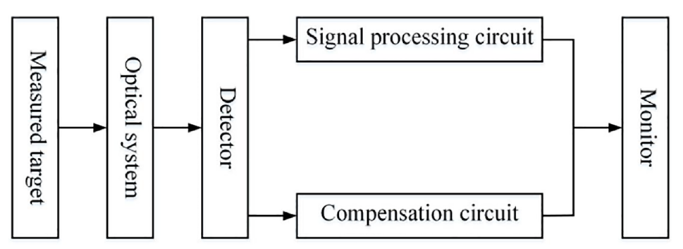
Infrared thermometer structure.
The test rig is required to carry out the temperature field test and analyze the influence of temperature on the testing device. Therefore, the test rig should be designed and created based on the testing device. The test stand is mainly composed of a computer, thermometer, testing device, power supply, and Gauss meter. The structure of the test bed is shown in Figure 4.
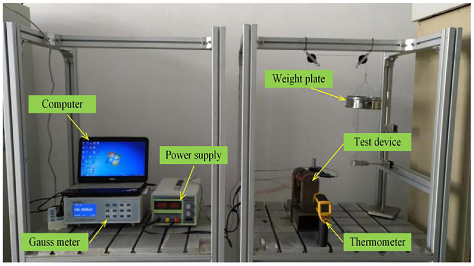
Test platform.
Structure and function of the testing device
MRF is mainly a suspension system composed of three parts: magnetic particles, base liquid, and additive. 18 MRF preparation19,20 is a multi-cycle process. This test uses base liquid displacement method and ball milling technology to prepare the MRF.
The MRF yield stress testing device can be divided into insulation, magnetic isolation, and magnetic conduction materials according to the magnetic properties of the materials used. Enameled wire winding is used to apply a magnetic field to the MRF coil winding, with the magnetic conductivity of magnetic circuit materials and the mechanical processing performance taken into account. The iron core and support materials are uniformly made of Q235 steel. In general, the temperature of the enameled wire coil winding is highest when the entire MRF yield stress testing device is operated. 21 Thus, the level of high-temperature resistance is an important material property of the enameled wire.
The schematic diagram of the designed yield stress testing device based on the principle of the pull-up method 22 is shown in Figure 5. The bracket, iron core, and liquid storage tank are connected together by circumferential welding. The magnetic circuit is the main part of the device. As shown in Figure 6, the closed magnetic circuit is selected to provide the maximum magnetic field required for the test and ensure the magnetic field distribution in the test slot is even. 23 The lifting block is inserted into the liquid storage tank containing the MRF. It will move relative to the MRF under force F of the weight loading, which will cause the shear phenomenon between the MRF and the surface of the lifting block. 24 The MRF yield stress is then measured.

Schematic of the MRF yield stress testing device based on pulling.

Magnetic circuit structure diagram of the MRF yield stress testing device.
Theoretical analysis of temperature field of test equipment
The testing device temperature field clearly shows how the temperature of the testing device changes over time. According to the principle of energy conservation, the unit volume of dxdydz is defined to confirm the heat transfer equation. Heat transfer is assumed to occur on the surface of each micro-element, and the vertical heat transfer rates of the surfaces of the individual micro-elements are
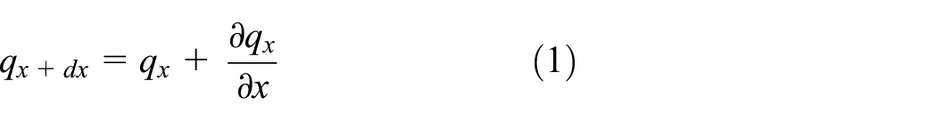


Heat transfer in the x direction is used as an example. Formula (1) shows that the x direction heat conduction velocity at
An analysis target with an internal heat source can be expressed as follows:

where

where
The outer surface of the yield stress testing device is often in direct contact with air because the Joule heat generated by the testing device windings must transfer heat through the portion in contact with the coil windings. The Joule heat generated by the coil passes through the internal heat conduction and outer surface of the device. The convective heat exchange with the air and device dissipates as heat radiates to the surrounding environment. The coil of the yield stress testing device is a stable heat source, and current I through the coil is direct current. The process of generating Joule heat 26 is represented by the following equation:

Given that the temperature of the coil varies, 27 the resistance value of the coil likewise changes with temperature. 28 Therefore, using a single volt-ampere formula to calculate the heating power results in a large error. The formula for introducing resistance and temperature is as follows:

where
Moreover, the diameter of the enameled wire used for winding the coil is the same. If the coil winding resistivity is unique, the heating speed of the coil winding per unit volume is

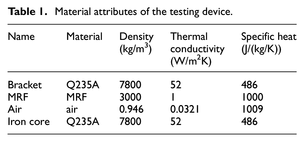
After the electric energy of the coil is converted into heat energy, the heat will pass through the support of the testing device, iron core of the coil, and MRF for heat conduction. Then, it will passes through the bracket, MRF, and outer surface of the coil and external environment convective heat exchange. Subsequently, the radiation heat dissipation will decrease. The material properties of the various materials are shown in Table 1 below.
Material attributes of the testing device.
The MRF yield stress testing device mainly exchanges heat with convective heat transfer and radiation heat exchange with the outer surface (Figure 7).

Heat transfer mode of the testing device.
Heat radiation and convection are combined into a composite heat transfer for the temperature field analysis of the yield stress testing device. The composite heat transfer coefficient 29 is

where

where ν is the relative velocity of the air and cooled surface;
The thermal conductivity of the enameled wire winding needs to be determined to complete the simulation analysis of the magnetic circuit. The enamel coating and wire diameter will affect the equivalent thermal conductivity of the coil. The flatness of the winding will affect the filling rate of the coil winding, which is related to the internal air gap. Thus, flatness is also a factor affecting the comprehensive thermal conductivity. Generally, the wire groove that is opened on the skeleton according to the wire diameter of the enameled wire can ensure that the winding is flat when the number of turns is large. In this study, the difference in temperature gradient in the coil is analyzed in the case of fine winding.
The thermal conductivities of the three materials in the enameled wire are as follows: copper (399 W/m2K), air (0.014 W/m2K), and insulating varnish (0.21 W/m2K). Heat is transferred in the conduction direction with good heat transfer, which is similar to the flow of current in the conductor. The mathematical model of the enameled wire winding is shown in Figure 8.

Winding model.
The relative area of each substance is derived by taking a small part of the enameled wire winding as the analysis object:

The thickness of the three materials is transformed by converting the winding portion of the enameled wire into a flat wall structure that has the same volume (Figure 9).


Flat wall model of winding.
The formula for the comprehensive thermal conductivity of the winding can be obtained by combining Formula (11):

Therefore, the thermal conductivity of enameled wire winding calculated by Formula (13) is 3.06 W/m2K. As a reference object, the thermal conductivity of the enameled wire must be tested. The results of the calculation for thermal conductivity of the enameled wire indicate that the thermal conductivity of the enameled wire is much smaller than that of copper owing to the presence of the insulating layer.
Experimental operation
Evaluating the operating characteristics of the MRF yield stress testing device is necessary to ensure that it can operate normally under different operating conditions and have high accuracy at varying operating temperatures. The two key indicators for setting up their test equipment are (1) measurement accuracy and (2) maximum working temperature value of the MRF yield stress testing device.
After the test platform is created, the experimental operation is carried out. First, the gap of the testing device is calibrated, and 1, 2, 3, and 4 gap numbers are set (Figure 10). The difference in the size of the four assembly gaps is considered. The dimensions of the four gaps are exactly the same. The two points on the first gap are marked with A and B, as shown in Figure 11. Then, the temperature changes under two gaps are simultaneously detected by the thermometer. Subsequently, monitoring point 1 is marked on the outer wall surface of the testing device, and monitoring point 2 is marked on the middle of the winding coil. The MRF marked monitoring point 3 in the liquid storage tank is used. The data of the three monitoring points are collected by the thermometer. Finally, the principle of pull-up method is adopted to keep the weight quality constant while yield stress is determined at different temperatures. In addition, the occurrence of MRF yield stress is controlled by controlling the current, thereby realizing continuous adjustability.

Assembly clearance.

No. 1 assembly gap and monitoring point.
Simulation and experimental result analysis
Analysis of temperature field simulation results
The testing device mesh model from the previous section is introduced into Fluent using Hypermesh, and the load and boundary conditions are applied. The model is subjected to steady-state and transient simulations of the temperature field. 30 After iterative calculation of a certain number of steps, the computer converges and the steady-state temperature field of the testing device is obtained. The simulation results are shown in Figures 12 (3D temperature field cloud map) and 13 (middle-section temperature field cloud map).

3D temperature field nephogram of the testing device.
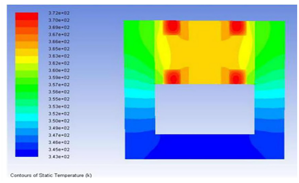
Temperature field nephogram of the middle section of the testing device.
A transient temperature field simulation of the testing device is required to obtain its temperature change from the initial to the maximum temperature. The total simulation time is set to 100 min, and the temperature changes at 10, 20, 40, and 90 min are observed, as shown in Figure 14.
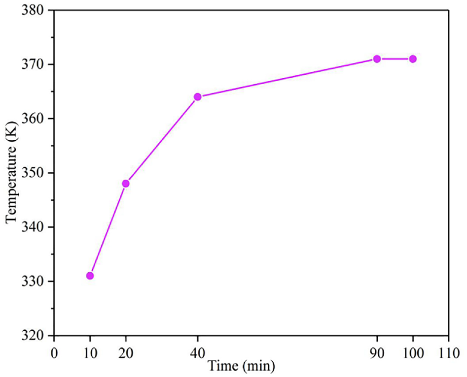
Temperature field change of the testing device at different times.
The combined results of the steady-state and transient simulations in Figure 14 indicate that the heat of the testing device is mainly concentrated on the upper part, especially near the winding. The temperature field of the MRF yield stress testing device reaches steady-state equilibrium at approximately 90 min. At this time, the coil winding temperature is up to 372 K and the MRF temperature is 365 K. The transfer speed of heat at the gap changes due to the presence of the assembly gap, and the temperature field distribution exhibits significant delamination at the assembly gap.As shown in the temperature field cloud diagram of the transient simulation, the heat at the windings is transmitted to the surroundings. Heat rapidly propagates in Q235 because it has excellent thermal conductivity. The thermal conductivity of the MRF and the transfer speed of heat therein are relatively small, and so the temperature of the MRF rises relatively slowly.
An assembly gap exists between the bracket of the testing device and the coil core portion, and the iron core and MRF reservoir portion are welded and assembled.Although the gap and the amount of air inside are relatively small, because the thermal resistance of the air is relatively large, the influence of the assembly gap on the temperature field still requires analysis.
In the temperature field simulation, when the boundary conditions are set, the air distribution in the assembly gap is assumed to be uniform. The assembly gap is set in the form of an air wall surface. The thermal conductivity of the assembly gap is equivalent to that of the air. The assembly gaps are set to 0.01, 0.03, 0.05, 0.1, 0.15, and 0.2 mm to calculate the steady state of the temperature field. 31 The calculation results are shown in Figure 15 below.

Parameter values of the general variable equation.
The simulation results indicate that as the gap increases, the heat dissipation of the testing device decreases and the steady-state temperature rises (Figure 15). The average steady-state temperature rises by approximately 2 K for every 0.01 mm increase. The calculation and simulation results indicate that the larger the gap, the higher the maximum temperature of the whole device. Controlling the assembly clearance of the testing device is essential to improve the stability and accuracy of the device operation. The assembly gap of the finished product is unknown due to the uncertainty of the assembly gap during processing. Thus, subsequent tests are required to determine the gap.
The thermal conductivity of the enameled wire is calculated as QQ. However, several sets of other values near the theoretical thermal conductivity are also used in the finite element analysis of the temperature field for comparative analysis. Figure 16 illustrates that the finite element simulation results of different thermal conductivities are different. The larger the thermal conductivity of the winding, 32 the stronger the heat transfer capability to the surrounding materials. Thus, the more stable the testing device, the lower the maximum temperature.
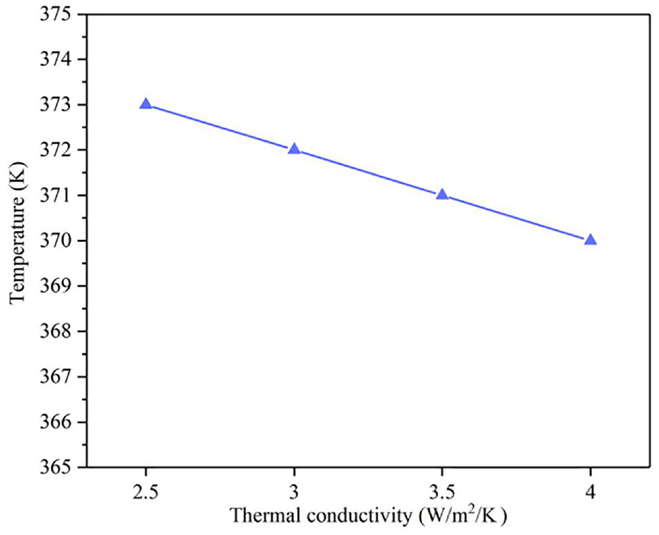
Temperature field distribution with different thermal conductivities.
Analysis of experimental results
The diameter of the enameled wire winding’s copper conductor is 0.5 mm, with a total of 42 layers and 2211 turns. During the test, the top temperature of the enameled wire winding was tested with a thermal detector. The test temperature and thermal conductivity of the winding were also compared with the simulation results under 2.5, 3, 3.5, and 4 W/m2K. The comparison between the test and simulation temperatures is shown in Table 2.
Comparison of test and simulation temperatures.

The relative error between the simulated and test temperature values is the smallest compared with the test data of the temperature field when the thermal conductivity of the enameled wire is WW. Thus, the thermal conductivity of enameled wire is 3.06 W/m2K.
This test presents four assembly gaps and sets two monitoring points (i.e. A and B). The simulation and test results are compared. The temperature changes were measured by the thermal detector with A and B at 30 min, and the test values were fitted with the simulated ones using Origin. The results are shown in Figures 17 and 18.

A point temperature test and simulation values.
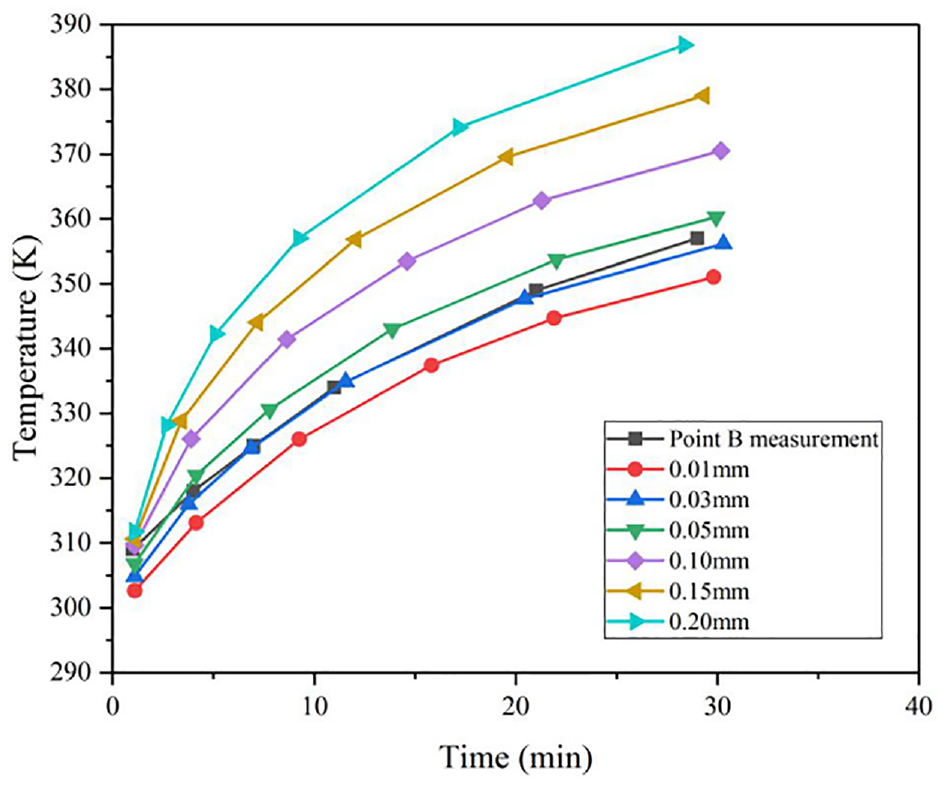
B point temperature test and simulation values.
The comparison results of the test values of A and B with the simulated ones show that the temperature of the two points continuously increases as the gap increases, 33 which is consistent with the theoretical analysis on the temperature field.Moreover, the comparison results of the test values of the two points in Figures 17 and 18 with the simulation ones indicate that the temperature test values of A and B are basically consistent with the simulated calculation values when the gap is approximately 0.03 mm. Thus, the assembly gap is determined to be 0.03 mm.
When the thermal conductivity of the testing device is 3.06 W/m2K and the assembly gap is 0.03 mm, the simulation results are obtained by substituting the simulation conditions, as shown in Figure 19. Clearly, the temperature of the device decreased compared with the previous simulation.

Temperature field nephogram of the testing device.
Furthermore, when testing the temperature field of the entire testing device, three monitoring points are preset for the temperature test. Then, the thermal detector is used to collect data from three monitoring points and compare them with the simulated temperature values of the three monitoring points. The comparison results are shown in Figures 20 and 21.

Test and simulation values for monitoring points 1 and 2.

Temperature test and simulation value of No. 3 monitoring point.
As shown in the above chart, the temperature field of the test and simulation test set reached a steady state at 100 min. The slope of the temperature curve is relatively large and tends to be stable at the beginning, consistent with the theoretical analysis on the temperature field. The absolute errors of the test and simulation values of the three monitoring points are then calculated. The analysis results are shown in Table 3 below.
Statistical table of temperature field data.

As illustrated in the table, the error between the test and simulation data of the three monitoring points is within a reasonable range.
The viscosity–temperature formula proposed by Reynolds 34 indicates that the operating temperature can affect the yield stress of MRF by affecting the viscosity of MRF.35,36 The characteristic curve of viscosity–temperature of the MRF shown in Figure 22 37 demonstrates that when the temperature is in the range of −40°C–0°C, the base liquid is solidified as the temperature decreases and the MRF changes. The liquid exhibits a solidification phenomenon, thereby making the viscosity large. When the temperature is between 0°C and 100°C, the thermal motion of the carrier liquid molecules becomes highly active as the temperature rises. Moreover, the attraction and friction between the internal molecules become small. Accordingly, shear stress and viscosity become small. When the temperature is higher than 100°C, the surface activity of the ferromagnetic particles of the MRF is lowered due to the volatilization of the carrier liquid and decomposition of the additive. Furthermore, the viscosity of the MRF at this time starts to increase gradually. The temperature exhibits a considerable influence on the yield stress because the viscosity is positively correlated with the yield stress of the MRF.

Viscous temperature characteristic curve of MRF.
The premise of measuring MRF yield stress is the yield phenomenon of MRF, which is actually a counterbalance process between the external and internal forces of MRF resisting deformation. When the external force is greater than the internal one, yield occurs; otherwise, it does not occur. The MRF yield stress can be loaded in two ways (i.e. keep the weight and input current constant). This test controls the MRF yield stress by controlling the input current. The magnetic field strength was tested at 0.3 and 0.4 T at different temperatures. The test results are shown in Figure 23.
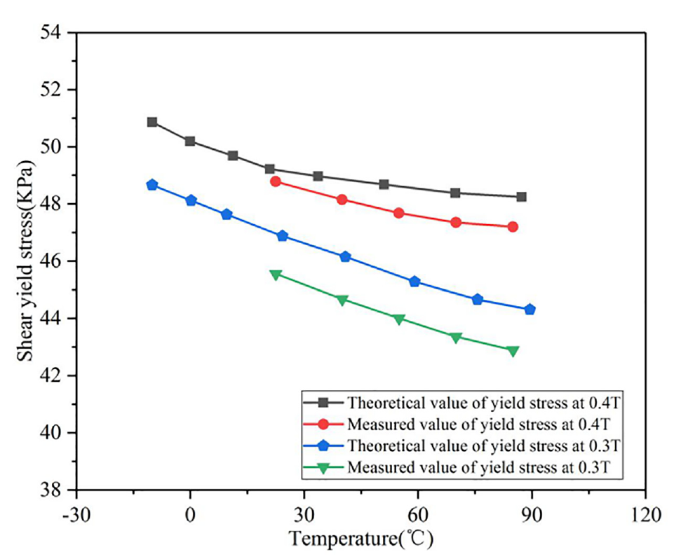
Theoretical and measured values of yield stress at magnetic field strengths of 0.3 and 0.4 T.
When the magnetic induction intensity is 0.3 T, the maximum deviation between the actual measurement and the theoretical calculation is 1.04 kPa and the absolute deviation is 2.15%. Meanwhile, when the magnetic induction intensity is 0.4 T, the deviation between the actual measurement and the theoretical calculation is 1.56 kPa and the absolute deviation is 3.4%. The yield stress of MRF decreases with increasing temperature. 38 Therefore, the temperature field has a considerable influence on the accuracy of the testing device.
Conclusions
On the basis of the theoretical study on the temperature field of the MRF yield stress testing device, finite element method is used to analyze the temperature field distribution of the testing device. Moreover, a temperature field test of different enameled wire thermal conductivities and assembly gaps is carried out, and the specific experimental data are used. The comparative analysis and finite element results are summarized as follows:
Simulation software is used to simulate the temperature field of the MRF yield stress testing device. When the temperature field reaches approximately 90 min, the steady-state balance is reached. Moreover, the temperature field of the testing device is 372 K, and the temperature at the MRF is 365 K. The hierarchical simulation of the transient simulation indicates that heat at the windings is the highest and spreads to the surroundings.
Different thermal conductivities of the enameled wire are used to simulate the temperature field of the testing device. Results indicate that the greater the thermal conductivity of the winding, the stronger the thermal conductivity to the surrounding material and the lower the maximum temperature of the testing device. Moreover, four assembly gaps are set to calculate the steady state of the temperature field. As the gap increases, the heat dissipation of the testing device decreases, the steady-state temperature rises, and the average gap increases by 0.01 mm. The temperature of the state increases by 2 K.
The thermal conductivity of the coil winding in the testing device is tested and verified using the created test platform. The thermal conductivity of the enameled wire is determined to be 3.06 W/m2K and the assembly gap is 0.03 mm. The comparison outcome between the simulation and test results indicates that the error is within 7.1%, and the yield stress testing device is optimized to improve the measurement accuracy.
Footnotes
Handling Editor: James Baldwin
Declaration of conflicting interests
The author(s) declared no potential conflicts of interest with respect to the research, authorship, and/or publication of this article.
Funding
The author(s) disclosed receipt of the following financial support for the research, authorship, and/or publication of this article: This work was supported by the Science and Technology Commission of Shanghai Municipality (Grant No. 19030501100).