
Abstract
In order to solve the load-sharing characteristics of face-gear four-branching split-torque transmission system (FGFBSTTS), the static load-sharing mechanical analysis model was established. In the model, the deformation coordination conditions of torsional angle and torque balance condition were considered. By using Loaded Tooth Contact Analysis (LTCA) technology of face gear and herringbone gear, the time-varying meshing stiffness was calculated. The influences of manufacturing errors, installation errors, I-stage pinion floating, II-stage pinion spline clearance floating, and radial limit ring clearance floating on the load-sharing characteristics are analyzed. The results show that the LTCA technology is more accurate to reflect the load-sharing characteristics of each meshing position. When the I-stage pinion and the II-stage pinion floated at the same time, the best load-sharing characteristics can be obtained. The load-sharing characteristics affected by manufacturing errors showed obvious periodic change. The radial limit ring plays a better auxiliary role in load-sharing characteristics. The theoretical results were compared with the experiments to verify the correctness of the theoretical analysis. The research results can provide a theoretical basis for the optimal design of the load-sharing structure, error control, and assembly of the face gear four branch transmission system.
Introduction
The face-gear four-branching split-torque transmission system (FGFBSTTS) has the characteristics of high accuracy of torque diversion, smooth operation, excellent work stability, and two-stage commutation deceleration function.1,2 It also has the same advantages of high bearing capacity, high power density, large transmission ratio, high torque, compact structure as the parallel-shaft cylindrical gear transmission.3,4 The system used the face-gear transmission characteristics and adopt the multi-branching load-sharing technology5,6 to meet the requirements of high speed and heavy-load, which can be promoted and applied in aviation, wind power, mining machinery, and other related fields.
The core problem of this system is to study the load-sharing characteristics. Litvin et al.7,8 analyzed the application of surface-gear branch transmission system in helicopter power transmission device. Zschippang et al. 9 analyzed the load distribution, transmission characteristics, and root stress of face gear transmission from the perspective of quasi-static conditions. Li et al. 10 studies the load sharing of the input pinion floating under the static load sharing of the concentric face gear. Mo et al. 11 studies the load sharing characteristics of multi power face gear split transmission system. Lin et al. 12 studied the method of establishing contact fatigue model and life prediction of gear pair under the condition of compound motion curve. Dong et al. 13 studied the assembly, power direction, and load distribution of concentric face gear split torque drive system. Dong et al. 14 studied the meshing efficiency of sliding friction spur gear based on load contact analysis. Zhao et al. 15 studied the quasistatic load sharing behavior of concentric torque-split face gear transmission with flexible face gear. Feng et al. 16 studied the modeling and analysis of torsional vibration of face gear pair. Wang and Kang 17 studies the design and finish machining of high precision face gear. Li et al. 18 studied the effect predictions of star pinion geometry phase adjustments on dynamic load sharing behaviors of differential face gear trains. In the research of these papers, most of the load sharing models are established to consider the fluctuation of the average meshing stiffness, which can not reflect the change of the meshing position points on the load sharing characteristics of the system. At the same time, the closed-loop characteristics of the power flow of the parallel axial gear branch transmission system are ignored, and a mathematical model reflecting the mechanical change process of the whole system load sharing is not established. Therefore, this paper takes FGFBSTTS as the research object. The load-sharing mechanical analysis model of FGFBSTTS is established. The influence of different error factors on the load sharing characteristics is revealed. The load-sharing mechanics under the condition of floating factor is analyzed. It provides a theoretical basis for further optimization design of the system under uniform load.
Load-sharing mechanical analysis model
FGFBSTTS is composed of I-stage face-gear and II-stage herringbone gear. Its structure is shown in Figure 1. I-stage pinion is simultaneously meshed with I-stage face-gear 1 and face-gear 2. The power is transmitted to II-stage gear pairs through the two elastic torsion shaft. II-stage pinion-4 and pinion-5 are meshed with II-stage herringbone idlers respectively. Four II-stage herringbone idlers are meshed with the output gear 10 at the same time. The load-sharing structure of this system is designed by adopting the double floating structure of I-stage pinion 1 with radial floating and II-stage pinion-4 and pinion-5 with Spline clearance floating.

Three-dimensional structure schematic diagram.
The gear parameters are shown in Table 1.
Gear parameters.

The schematic diagram of the II-stage gears and radial limit rings is shown in Figure 2.

Schematic diagram of position structure of gear and radial limit ring.
The function of radial limit rings is to prevent the excessive floating of the II-stage pinion-4 and pinion-5 from the meshing state, so that the floating pinion is kept in the space specified in the radial limit ring. The outer diameter of the radial limit ring is equal to the pitch diameter of the II-stage pinions and idler gears. The II-stage herringbone idler gears are also designed with radial limit rings at both ends of gears.
The static torque distribution analysis model and the torsion angle distortion relationship are shown in Figure 3.

Schematic diagram of static torque distribution analysis model.
The input torque is T1 and output torque is T10. The meshing torque of each gear pairs can be expressed as following

Here, Iij is equal to rbj/rbi. Tij is the acting torque of the gear pair ij, Tji is the reaction torque of the gear pair ji, rbi and rbj is the base circle radius. For the face-gear, I12 = I13 = L0/rb1, L0 is base circle radius of face-gear, L0 = (L1 + L2), L1 is the inner radius of the face-gear. L2 is the outer radius of the face-gear.
According to the torque action relation, the equilibrium equations can be obtained as follow

Here, Tij(k) is the torque of gear j to gear i at the meshing position k in a meshing cycle.
According to LTCA theory, 14 k indicates that a meshing period is divided into five equal parts, that is, k = 1, 2, … , 5. As shown in Figure 3, under the action of torque Tij(k), φ i and φ j is torsional angular displacement deformation respectively. The transmission errors can be obtained and shown as following

In a meshing cycle, Tij(k) is the torque of gear j and gear i meshing at the k-th meshing position. Δφ ij (Tij(k)) is a function of Tij(k). Δφ i (i = 1, 2, … , 5) is the torsional angle error of the gear i.
Through the finite element calculation and the gear geometric contact simulation analysis program, the several groups of load transmission errors at the k-th meshing position are calculated by using LTCA. The functional relationship between the load transmission errors and the torque is fitted, and the time-varying meshing stiffness of each pair of gears is obtained. The following relation is satisfied with the integrated time-varying meshing stiffness and the load transmission errors.
The time-varying meshing stiffness and load transmission errors satisfy the following formula

Here, Kmij(k) is the time-varying meshing stiffness. αn is the normal meshing pressure angle. The torsional angular displacements Δφ24 (T24(k)) and Δφ35 (T35(k)) of elastic torsion axis can be expressed as follows
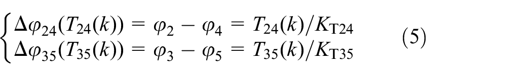
Here, KT24 and KT35 are the torsional stiffness of elastic torsion shaft.
Combined with equations (3) and (4), the torsional angular displacement deformation coordination conditions without elastic support are deduced to follow

Through combining with formulae (2), (5), and (6), the calculation model of torque distribution under rigid conditions is obtained. Under the conditions of given input torque T1 and integrated time-varying meshing stiffness, the unknown torque Tij(k) of each gear pairs can be obtained.
Load-sharing coefficient calculation
The equivalent meshing angle errors caused by manufacturing errors are Δφ0 Ei and Δφ0 Ej . It can be expressed as follows:

Here: ΔEi and ΔEj are the eccentricity error amplitudes of each gear i and face-gear j. ηi and ηj are the eccentricity error direction angles. ω i and ω j are the angular velocity. ϕ i and ϕ j are the initial phase angle.
The equivalent meshing angle errors caused by installation errors are Δφ0 Ai and Δφ0 Aj . It can be expressed as follow

Here: ΔAi and ΔAj are the amplitudes of installation error of gear i and face-gear j.δ i and δ j are the direction angle of installation errors.
Under the conditions of manufacturing errors and installation errors, the equivalent meshing angle errors caused by radial floating of the I-stage pinion is defined as Δφ01, and the equivalent meshing angle errors caused by Spline clearance fluctuation of the II-stage pinion is defined as Δφ04 and Δφ05:

Here, Δx1, Δx4, and Δx5 are the floating micro-displacements of pinion 1, 4, and 5 in the x-direction. Δy1, Δy4, and Δy5 are the floating micro-displacements of pinion 1, 4, and 5 in the y-direction.
Under the action of elastic support, the relative angular displacement of the axial deformation caused by each gear component is Δφ0 Tij .

Here: xi and xj are the lateral bending axial deformation of gears i and j along x and y directions. χ ij is the angle of the meshing line of each gear pair ij with x-axis. χ ij meet the following relationship

Here: γ ij is the positive angle between centerline of gear pair ij with the x-axis.
The meshing errors Δφ0 ij is obtained and expressed as follows
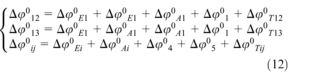
The meshing transmission errors Δφ E ij (Tij(k)) is equal to Δφ ij (Tij(k)) + Δφ ij 0. The equations (3) and (13) are combined to get a set of equations and shown as follow

Substituting equations (5) and (13) into equation (6), the equations of deformation coordination condition of torsional angle can be obtained and shown as follow


This condition is beneficial to the overall design of the system and the load-sharing process analysis.
The moment balance equation of each component under elastic support conditions are as follow

Here, Kxi and Kyi are the elastic support stiffness.
The balance equations for the radial floating of the I-stage pinion can be expressed as follow
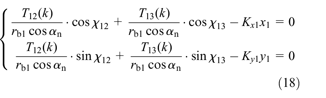
Here, x1 and y1 are the floating value of pinion 1 in the x and y directions. The radial floating value R1 is equal to square (x12 + y12)
The equilibrium equation of the spline clearance floating of the II-stage floating pinion-4 and pinion-5 is:
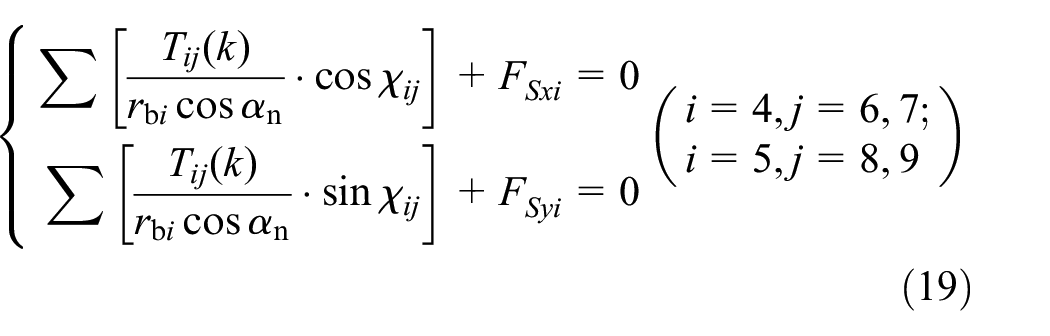
Here, Fs xi and Fs yi are the support reaction forces of the spline shafts in the x and y directions. Fs xi and Fs yi are expressed as follow

Here, Ri (i = 4, 5) is the floating value of floating pinion-4 and pinion-5. S1 and S2 are the radial clearance of internal and external spline. Fm is the friction of internal and external spline and equal to τFN, FN represents the positive pressure between the internal and external splines, τ is the friction coefficient, τ is equal to 0.1. Kw is the bending stiffness of the spline shaft. xi and yi is the floating micro-displacement of gear i (i = 4, 5) in x and y direction. ξ i is the direction of the vector (xi, yi). When the bearing reaction force is less than the frictional force Fm, the floating value satisfies 0 < Ri < S1, no slippage is generated between the internal and external splines, the bending stiffness of the input shaft is adapted to the change of the floating position. When the bearing reaction force greater than the friction force Fm, the floating value satisfies S1 < Ri < S2, the internal and external spline will produce slight slip, and the slippage will be suitable for the position change of the floating pinion i (i = 4, 5), that is, the floating pinion is in a completely floating state. When the slippage between the internal and external splines exceeds the S2, the floating value satisfies S2 < Ri, that is, the internal and external spline eliminates the radial clearance quantity, and the change of the position of the floating pinion is determined by the bending stiffness and friction of the spline shaft.
The floating pinion i (i = 4, 5) automatically finds its central position under the combined action of two intermeshing idlers and the support force of the radial limit ring. Taking the floating pinion-4 as an example, Figure 4 shows the mutual closed mechanical relationship.

Schematic diagram of closed mechanical relation of floating pinion-4.
j wtij (ij = 46, 47, 610, 710) is the circumferential backlash between the gear i and the gear j. When the floating pinion-4 meshes with the idler gear 7, the floating pinion-4 has a tendency to float upward to the position O4′, in order to eliminate the circumferential backlash jwt46 between the floating pinion-4 and the idler gear 6 and eliminate the circumferential backlash jwt610 between the idler gear 6 and the gear 10. When the floating pinion-4 meshes with the idler gear 6, the floating pinion-4 has a tendency to float downward to the position O4. Therefore, the center of the floating pinion-4 is floating between O4 and O4′. The floating range is H1. If the floating equilibrium is out of the range, the balance point of the floating pinion will be stayed on the boundary of the radial limit ring. The radial limit ring provides the bending support force.
Because of the radial limit ring only allow the floating pinion i (i = 4,5) to produce displacement in the radial along the y-direction and the x-direction is completely restricted, the floating space is considered as a long and narrow drum shaped area. The floating boundary model under the support of the radial limit ring support is shown in Figure 5.

Establishment of a floating boundary model.
The boundary conditions of the drum region are composed of the boundary conditions of the pitch circle of the meshing two large gears and the boundary conditions of the limit ring along the radial direction. The closed area determines whether the equilibrium position of the floating gear is within the allowable floating range of the radial limit ring. The floating area is defined as h1 + h2. h1 is the upward floating value. h2 is the downward floating value. The force balance condition of the radial limit ring is as follows:

Here, FCxi and FCyi are the supporting reaction of the limit rings along x-axis and y-axis.
The torsion angle deformation coordination conditions, moment equilibrium equation, floating equilibrium equation, and limiting ring equilibrium condition are simultaneously solved to obtain the torque Tij(k).
The load-sharing coefficient of the I-stage gear pairs and the II-stage gear pairs are ΩI and ΩII. The load-sharing coefficient of the system is ΩZ = max[ΩI, ΩII].

Example analysis
Given the input power is P = 2000 kW, the input speed is 8780 r/min, and the installation error and eccentricity errors are 50 μm. Given the bending rigidity Kw of spline shaft is 1.78 × 10⁷ N·m−1 and the bearing support stiffness of the sun gear Ki is 5.5 × 10⁸ N·m−1.
The solution of time-varying meshing stiffness is carried out according to reference [6]. LTCA method is used to calculate the time-varying meshing stiffness, LTCA model of driving gear and driven gear is shown in Figure 6.
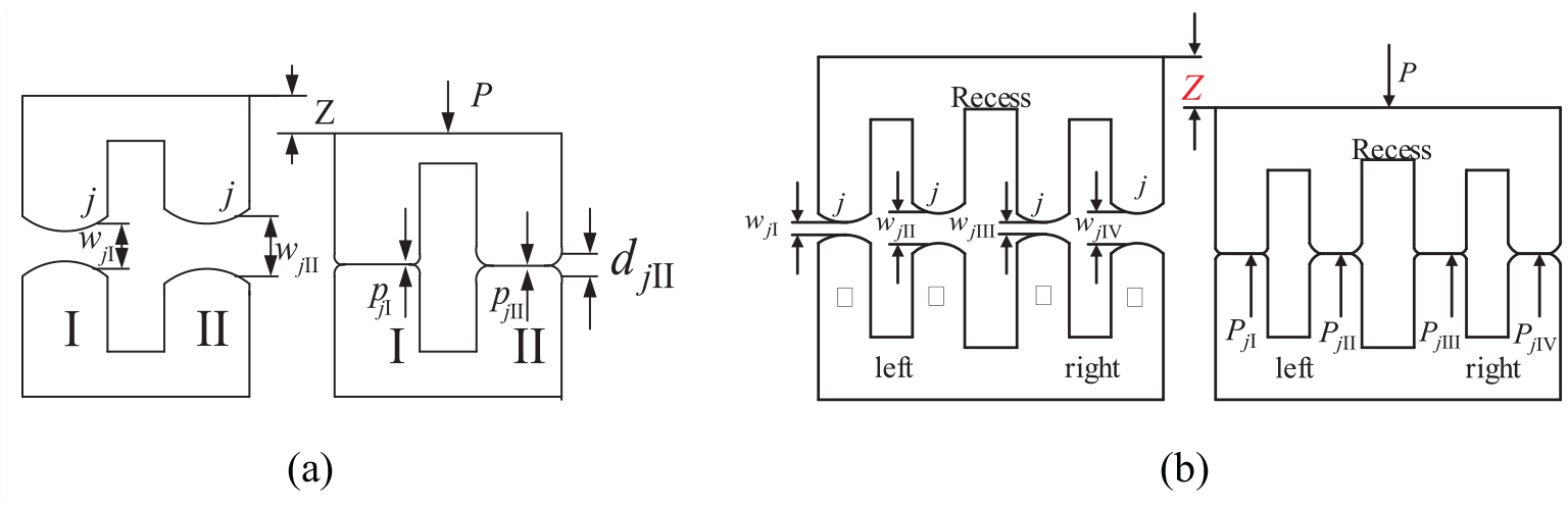
Load tooth contact analysis model of each gear pair: (a) face-gear pair and (b) herringbone gear pair.
Under the load P, the driving gear goes through an approach Z. Due to the tooth deformation, contact load will become distributed. After contact deformation, the state can be described by the following equation for the tooth pair k
Here, jk is a point along the relative principal direction, k = I, II,
LTCA calculation is carried out for all the meshing positions in a meshing cycle, and Z, [P], and [d] are obtained. Z is the normal linear displacement transmission error of the gear after deformation under the normal load P of the current contact position, which is transformed into the angular displacement error Δφsp.
The elastic deformation of the gear teeth under normal load, including the geometric bending deformation δB of the gear teeth, the elastic deformation δM at the root of the gear teeth, and the contact deformation δC at the meshing point, is obtained. The relationship between the comprehensive elastic deformation Δφsp[Tsp(k)] and the transmission torque Tsp(k) of the gear pair is as follows

Here, a, b, and c are constant terms in the formula, which are determined by the geometric parameters of the gear and the coordinates of the meshing position, Tsp(k) (k = 1, 2, … , 5) is the torque of the k-th meshing position in a meshing cycle. δB = a, δM = bTsp(k), δC = cTsp(k)2/3.
Through the finite element calculation and the gear geometric contact simulation analysis program, when the gear pair is in the meshing position k, solving equation (23), the load transmission error ΔδT (0.1Tsp(k)), ΔδT (0.5Tsp(k)), and ΔδT (0.9Tsp(k)) are obtained. The results are brought into the formula (24), and the coefficients a, b, and c are obtained, and the function relation between the loaded deformation of the driving gear and driven gear and the nominal load is obtained. The time-varying meshing stiffness of driving gear and driven gear is obtained. The following relation is satisfied with the integrated time-varying meshing stiffness Ksp of driving gear and driven gear with the corresponding angular error Δφsp (Tsp(k))

The meshing stiffness curve of each gear pair is shown in Figure 7.

Time varying meshing stiffness curve of each gear pairs: (a) I-stage pinion and face-gear, (b) II-stage pinion and idler gear and (c) II-stage idler gear and big gear.
Here, the three curves are the meshing stiffness curves under the loaded of T, 0.9T, and 0.95T, respectively. The meshing stiffness fluctuation range of I-stage face-gear pairs is (7.46 × 10⁵–9.27 × 10⁵) N·m−1. The meshing stiffness fluctuation range of II-stage idler gear pairs is (3.77 × 10⁶–4.78 × 10⁶) N·m−1. The meshing stiffness fluctuation range of II-stage big gear pair is (6.17 × 10⁶–6.68 × 10⁶) N·m−1. Due to the different meshing stiffness of each meshing position of the tooth surface, the load-sharing coefficient of different meshing positions does not change much.
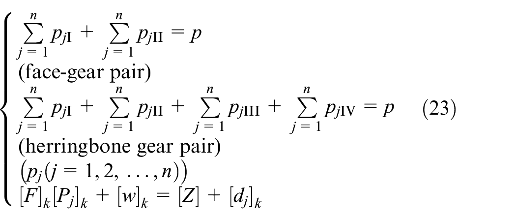
Figure 8 shows the curve of load-sharing coefficient which varies separately with installation error.
Curve diagram of load-sharing coefficient changing independently with installation errors: (a) Installation errors of I-stage pinion and face-gear and (b) Installation errors of II-stage gear.
As can be seen from Figure 8, in terms of the influence of the installation error in I-stage on the load sharing coefficient of the system, gear 1 has the largest influence, gear 2 has the smallest influence, and gear 3 has the middle influence, but the influence of the overall I-stage error is very small. It can be seen from Figure 8(b) that gear 6 in II-stage has the greatest influence, and gears 7, 8, 9, and 10 have the similar influence, but far less than gear 6. The overall influence of II-stage is much greater than that of I-stage. Generally speaking, with the increase of installation error, the load-sharing coefficient of the system increases, and the load-sharing characteristics decrease.
Figure 9 shows the curve of load-sharing coefficient which varies separately with manufacturing error.

Curve diagram of load-sharing coefficient changing independently with manufacturing error: (a) Manufacturing errors of I-stage pinion and face-gear and (b) Manufacturing errors of II-stage gear.
It can be seen from Figure 9(a) that the manufacturing error of gear 1 has a greater influence, the manufacturing error of gear 2 and gear 3 has a smaller influence, and the overall I-stage has a weaker influence. The manufacturing error of the II-stage gear 8 has the greatest influence on the load-sharing coefficient, while the manufacturing error of the I-stage pinion and face gear has a few influences on the load-sharing coefficient. With the increase of manufacturing error, the load-sharing coefficient of the system increases, and the load-sharing characteristics decrease.
Compared with Figures 8 and 9, when the installation error and manufacturing error are equal to 50 μm, the load-sharing coefficient ΩI is equal to 1.0049 and 1.0121 respectively, and the load-sharing coefficient ΩII is equal to 1.1602 and 1.1144 respectively. The influence of installation error and manufacturing error on the load-sharing coefficient of each gear in II-stage is more obvious. The influence of installation error on the overall load sharing characteristics is less than that of manufacturing error. In other words, the influence of the gear installation and manufacturing errors in II-stage on the load sharing performance of the system is more sensitive than that in I-stage. Therefore, we should pay more attention to the installation and manufacturing accuracy of the gear in II-stage.
When the installation error and manufacturing error exist at the same time, the floating of I-stage and II-stage gears is not considered, and the torque fluctuation curve of the system is shown in Figure 10.

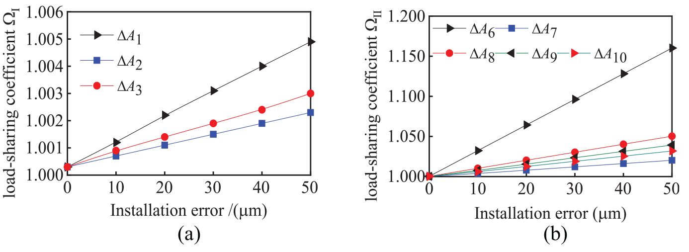
The curve of torque distribution for each gear pair: (a) Torque distribution of I-stage gear pair and (b) Torque distribution of II-stage herringbone gear pair.
As shown in Figure 10(a), under the standard errors free condition, the theoretical average torque distribution of I-stage gear pairs is 1087.6 N·m. The torque T12 and T13 fluctuate at 1107.7 and 1068.5 N·m. The torque distribution is 50.88% and 49.12%, respectively. The I-stage load-sharing coefficient is 1.019 and 0.983, respectively. As shown in Figure 10(b), the theoretical average torque distribution of II-stage gear pairs is 7571.7 N m. The torque T610, T710, T810, and T910 fluctuate at 7064.4, 8079.1, 7321.8, and 7821.6 N·m. The II-stage load-sharing coefficient is 0.933, 1.067, 0.967, and 1.033, respectively. The overall load-sharing coefficient of the system is ΩZ = 1.067. Under the common influence of the error, the torque distribution is uneven, and the torque distribution is different at the different meshing position points of each tooth. The torque distribution at the position point 5 of the I-stage meshing point is better, is close to the average torque distribution, and the meshing position point 4 of the herringbone gear pair is good at the torque distribution.
When considering the effect of spline clearance floating, the floating value of pinion-4 and pinion-5 is calculated and equal to 0.356 and 0.238 mm, respectively. Given the value of the spline clearance equal to 0.4 mm, the torque distribution of the gear pair of the system is obtained and shown in Figure 11.
Torque distribution of gear pairs for full floating condition: (a) Torque distribution of I-stage gear pair and (b) Torque distribution of II-stage herringbone gear pair.
The load-sharing coefficient of I-stage branch transmission is 1.014 and 0.986, and the load-sharing coefficient of II-stage branch transmission is 0.984, 1.016, 0.993, and 1.007 respectively, and the load-sharing coefficient of the system is ΩZ = 1.016. Under the full floating conditions, the load-sharing mechanical characteristics of the system have been greatly improved.
Figure 12 shows the curve of load-sharing coefficient of II-stage changing with spline clearance.
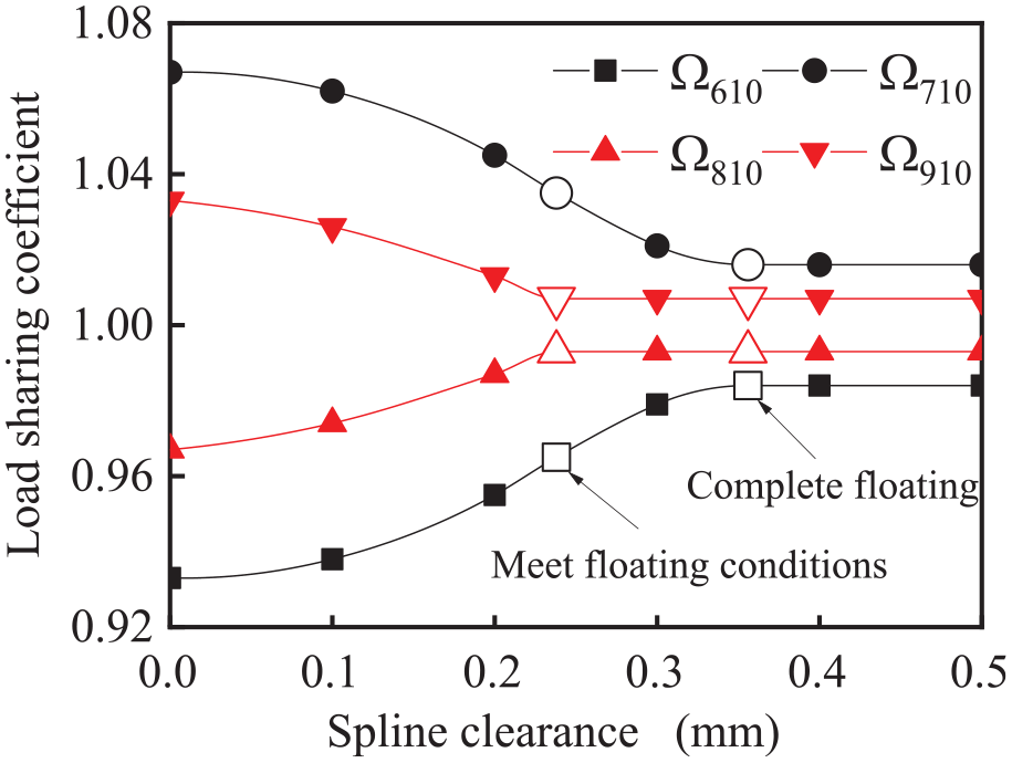
Load-sharing coefficient changed with spline clearance.
When the spline clearance is equal to 0 mm, the bending stiffness is equivalent to the supporting condition. With the increases of spline clearance, the load-sharing coefficient decreases gradually. When the spline clearance is equal to 0.3 mm, the floating pinion-4 does not have a full floating, however, the floating pinion-5 have a full floating, so the gear pair 810 and the gear pair 910 reach the load-sharing state. Floating pinion-4 and pinion-5 have a certain floating independence.
Simultaneously, the floating pinion i (i = 4, 5) will be also restrained by the radial limit ring.
When given the installation errors along the y-direction are ΔAy6 = 0.1 mm and ΔAy9 = −0.1 mm, respectively. The change of the load-sharing coefficient with the radial limit ring clearance is shown in Figure 13.
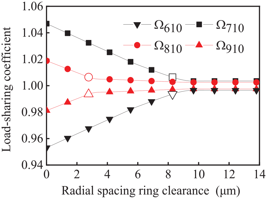
Load-sharing coefficient changed with radial limit ring clearance.
The floating pinion-5 satisfies the condition of final floating when the radial limit ring clearance is given 2.91 μm. The floating pinion-4 satisfies the condition of final floating when the radial limit ring clearance is given 8.36 μm. Figure 13 shows that the larger the value of circumferential radial limit ring clearance, the better the load-sharing characteristics of system. When the value of the circumferential backlash is equal to 0 μm, the support of the floating pinion i (i = 4, 5) is equivalent to the rigid support, the load-sharing coefficient is Ω710 = 1.047 and Ω810 = 1.019. When the value of the circumferential backlash is large enough, the system will achieve a completely ideal load distribution. The load-sharing coefficient is Ω710 = 1.004 and Ω810 = 1.003.
Due to the support reaction of the radial limit ring, the floating pinion i (i = 4, 5) cannot freely float, the central equilibrium position of the floating pinion i (i = 4, 5) will be finally fell on the boundary of the radial limit ring.
Figure 14 is a central locus diagram of the floating clearance of the II-stage pinion-4 and pinion-5.
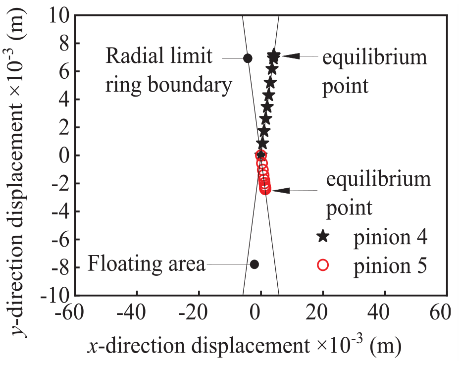
Floating trajectory curves of floating pinion-4 and pinion-5.
Due to the transverse (x-direction) gap of the radial limit ring is zero, the II-stage floating pinion i (i = 4, 5) gets the equilibrium point at the boundary of the limit ring. Under the action of the radial limit ring, the balance point coordinates of the II-stage floating pinion i (i = 4, 5) are (0.00414, 0.00713) and (0.00137, −0.00237), both of which fall on the boundary of the radial limit ring, and the floating value of the II-stage floating pinion i is obviously larger than the floating value of the I-stage pinion-1.
Experimental verification
Schematic diagram of the experimental principle is shown in Figure 15. The drive is provided by a DC speed-regulating motor. The main test gearbox is a face gearbox. The input spur gear is meshed with the two face gears. The test gearbox is a herringbone gear four-branching cylindrical gearbox. The box and the shaft are connected to form a closed loop. The two-way split active test box (4) of face gear is connected with high precision speed and torque measuring instrument (11) through precise elastic sheet coupling (9). Then, the elastic torsion shaft (5) is connected with the pinion of the cylindrical gear four-way split-torque passive test box (15). The output shaft of the DC speed regulating motor is connected with the acceleration sensor (3) through an elastic sheet coupling (2). The elastic coupling (2) is connected with the input shaft of the face gear box.
Schematic diagram of the experimental overall structure.
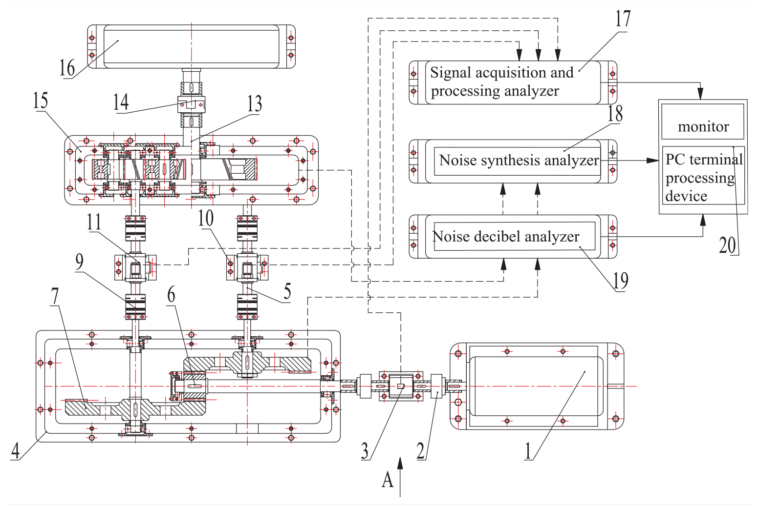
As shown in Figure 16, the external parts of the face gear two-way split-torque test box and the cylindrical gear four-way split-torque test box are provided with sound insulation covers (22) and (21), respectively. Seismic isolation devices (8) and (12) are installed at the bottom of two-way split-torque test box for face gears and four shunt passive test boxes for cylindrical gears. The permanent magnet DC motor is mounted on a fixed support (25). The neutrality and flatness are adjusted by leveling screw (26). The bottom of the bracket is provided with a shock-proof isolation layer (24), which reduces the impact of vibration and improves the measurement accuracy. The high precision speed and torque measuring instrument is connected with external devices including signal generator, excitation source and instrument amplifier, signal acquisition and processing analyzer (17), noise decibel analyzer (19), and noise comprehensive analyzer (18). The output end of the instrument amplifier is connected to the analog signal input end of the data acquisition card. The data acquisition card is connected with the bus of the PC terminal processing device (20). The output terminals of two signal amplifiers are connected with one oscilloscope.

Front view of the overall structure of the experiment.
The load-bearing experiment process includes the following four aspects:
1. After the base is leveled, the installation surface gear two-way split active test box and the spur gear four-way split-torque passive test box, as well as the DC speed-regulating motor, high-precision torque sensor, acceleration sensor, and so on. Adjust the coaxiality between the high-precision torque sensor, the two-way split-torque active test box of the face gear and the four-way split-torque passive test box idler input shaft.
Adjust the coaxiality between the acceleration sensor, the DC speed regulating motor and the face gear two-way split active test box input shaft.
2. The high precision torque sensor is calibrated and calibrated. Set the frequency of the inverter, set the input current value of the electric dynamometer, and test the control system to warm up for 30 min to complete the system debugging. The two-way split active test box of the opposite gear and the four-way split-torque passive test box of the cylindrical gear are used for running-in test and static loading test. The relative loads on each branch at different rotational speeds and the different input power values are measured, and the relative loads on the branches at different power input values.
3. As shown in Figure 17, the high-precision torque sensor is used to test the axial force on the torsion axis. The torque sensor is calibrated before the test, and the calibration data is linearly fitted to obtain the calibration error. The integrated error of the test system is squared. Calculated to meet the test accuracy requirements, the system’s comprehensive error of ±0.1% can meet the test accuracy requirements.
4. Acquisition of noise signals from two shunt active test boxes of face gears and four split-torque passive test boxes of cylindrical gears is carried out, which are input to noise decibel analyzer (19) and noise comprehensive analyzer (18), and further processed by PC terminal processing device (20). The data are recorded and processed by the data acquisition program of the computer processing workstation. The frequency value of the signal produced by the signal generator of the loading control system of the electric dynamometer is changed step by step, and the magnitude of the axial force and the noise when the different frequency values are recorded and saved. Change the speed of DC speed regulating motor step by step, adjust the range of 0–12,000 r/min, record and save the axial force of different speed.

Block diagram of the axial force test system.
The comparison between theoretical calculation results and experimental results is shown in Table 2. Here, the value of the input speed is constant, only the value of the input power is changed from 20% to 160%. Here, Tin = 1100 N·m.
Load-sharing coefficient under different loads.

As can be seen from Table 2, the load-sharing coefficient obtained by the test is 10% higher than that obtained by the theoretical calculation. This is due to the theoretical calculation value is an ideal state of the theoretical value, is the design of the ideal value, due to a series of factors of machining and assembly, heat treatment and other materials, the actual situation and the theory of state is different, and the testing error, also exist in the test system so that the experimental and calculated values are the difference. However, the experimental results are in line with the range of the load-sharing coefficient 1.1–1.5 recommended in the general project.
Figure 18 shows a diagram of the curve of the load-sharing coefficient changed with the input torque. When the input torque is equal to 283 N·m, the load sharing coefficient is 1.139 and 1.078, respectively. With the increase of input torque, the load sharing coefficient decreases gradually, and the load sharing performance is improved. The experimental data and the theoretical calculation data have a good consistency. It can be seen from the calculation that the test data is about 10% larger than the theoretical calculation value, which is basically within the allowable error range.
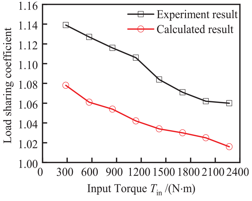
Relationship between input torque and load-sharing coefficient.
In summary, the error between the experimental results and the theoretical analysis values is acceptable, and the mechanical model established in the theoretical analysis and the solution method are correct.
Conclusions
The load-sharing coefficient increases with the increase of installation error and manufacturing error, and the error is the main factor affecting the load-sharing characteristics. In the case of the comprehensive influence of manufacturing error and installation error, the II-stage gears have the greatest influence on the load-sharing. In the process of processing and manufacturing, the influence of II-stage gears should be mainly considered.
By using LTCA method, the influence of the mechanical characteristics of each meshing position on the load-sharing coefficient is fully explained. The relationship between the tooth surface contact characteristics and load-sharing characteristics can be more accurately reflected. This method can obtain better load-sharing characteristics and provide a theoretical basis for tooth surface optimization design.
By adopting the double floating load-sharing structure design of radial floating and spline clearance floating, a four-branching transmission system structure with good load-sharing capacity can be obtained. The design should mainly consider the spline clearance and the radial limit ring clearance required to meet the floating of II-stage pinion.
Footnotes
Appendix
Handling Editor: Harshit Arora
Declaration of conflicting interests
The author(s) declared no potential conflicts of interest with respect to the research, authorship, and/or publication of this article.
Funding
The author(s) disclosed receipt of the following financial support for the research, authorship, and/or publication of this article: This research was funded by National Natural Science Foundation of China (51705390), Innovation Capability Support Program of Shaanxi (2020KJXX-016), Scientific Research Program Funded by Shaanxi Provincial Education Department Program (20JC015). Principal foundation project of Xi’an Technological University (xgpy200201), the Natural Science Foundation of Shaanxi Province (2021JM-428).