
Abstract
A new type of gear pair, the curve-face gear pair, composed of a curve-face gear and a non-circular gear with mutual engagement, was proposed to achieve variable ratio transmission of motion and power between the intersecting axes. Geometric error detection is required to evaluate the grade of the manufactured gears. Due to the complexity of the curve-face gear, direct detection has been conducted in a very limited way. In this article, a measurement method aimed at curve-face gear pair artifacts is presented based on the computer numerical control gear measuring center. By comparing the measured coordinate data of the surface points with the corresponding theoretical data, various errors such as tooth profile error and pitch deviation can be obtained, and accuracy grades are evaluated with reference to accuracy standards for cylindrical gear and bevel gear. The developed method is simple and robust without requiring a special measuring device; hence, it can be applied for the industrial practice as a means for measuring the tooth profile and pitch deviations which cannot be measured by conventional methods.
Introduction
Gears are crucial components for modern precision machinery as a means for power transmission mechanism. Face gear drive is composed of a cylindrical gear and a bevel gear meshing with each other, which has unique advantage in heavy-duty and high-speed occasion such as helicopter transmission system. 1 Curve-face gear pair is proposed based on the face gear pair, generated by replacing cylindrical gear in face gear pair with a non-circular gear. It is composed of a non-circular gear and a curve-face gear in order to realize variable ratio transmission between the intersecting axes. 2 The relevant researches of curve-face gear, especially the geometric error detections, mainly draw lessons from the existing cylindrical gear and face gear.
For gear drives, the requirements are different in various machineries, but main requirements such as working accuracy, transmission efficiency, and load distribution uniformity are all related to gear accuracy.3,4 Pitch deviation and tooth profile error are important factors influencing gear accuracy. A lot of researches on measurement have been done, and two main methods are widely used to measure the errors, which are specialized measuring instruments, such as gear circular pitch measuring instrument to measure pitch deviation and involute tester to measure profile error, and universal measuring instruments, such as gear measuring center and coordinate measuring machine.5,6 Nowadays, the researches on geometric error detection mainly focused on the following. (1) The development of novel measuring device using new principle and structure.7–9 Some novel measuring device are developed, such as a transmission error tester for face gear based on single-flank rolling principle, which can inspect several errors such as pitch deviation and transmission error. 7 Tang et al. 8 developed a gear measuring using double-flank rack probe (DFRP) method, which can be used to measure pitch and profile deviations on the left and right flanks simultaneously. (2) New measurement and evaluation methods of geometric error using universal measuring instruments.10–13 For example, Guenther 10 proposed a method to evaluate runout deviation at bevel gears based on pitch measurements using coordinate measuring machines. Sánchez et al. 11 introduced geometric principles for analyzing hypoid gears in coordinate measuring machines and obtained a method to trace the tooth shape of hypoid gears. Suh et al. 12 measured spiral bevel gear tooth using a coordinate measuring machine and obtained profile error applying profile error measurement algorithm. For detection of bevel gear and cylindrical gear, there exist a variety of equipment and standards around the world,14–16 while there is not any specialized equipment or standard for the detection of curve-face gear. Thus, gear measuring center is used to measure the tooth flank, and a method to obtain and evaluate pith deviation and profile error using measured points is developed in this article.
Curve-face gear is a new type of gear; in order to verify the practicability and correctness of the design, the curve-face gear pair was processed by three different ways, that is, five-axis computer numerical control (CNC) machining, additive manufacturing, and composite machining (combining additive manufacturing and five-axis CNC machining).17–18 Finally, a kind of pitch deviation, profile error detection, and evaluation method for curve-face gear pair artifacts are put forward based on the P26 automatic CNC-controlled gear measuring center from Klingelnberg of German, and related researches are carried out.
Design of curve-face gear pair
The curve-face gear pair drive is composed of a curve-face gear and a non-circular gear with mutual engagement. During the process of engagement, pitch curves of curve-face gear and non-circular gear do pure rolling with each other. As shown in Figure 1, at the initial moment, pitch curves of the curve-face gear pair contact at point
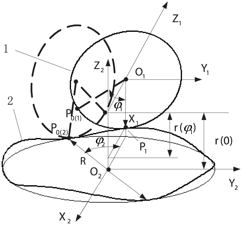
Pitch curves of the curve-face gear pair. 1: non-circular gear; 2: curve-face gear.
Pitch curves of the curve-face gear pair
Non-circular gear is used to transmit inhomogeneous motion between two shafts, which has many advantages than other mechanism. The most used non-circular gears are ellipse gear, eccentric gear, and Pascal spiral gear. In this article, the pitch curve of non-circular gear is elliptic curve.
According to the spatial meshing theory and coordinate relation, the complex pitch curve of curve-face gear can be deduced from the readily available non-circular gear. 2 The equation of the pitch curve of curve-face gear can be expressed as follows

where
Tooth profile of the curve-face gear pair
Tooth profile of non-circular gear can be obtained by generating motion of cylindrical gear on pitch curve of non-circular gear. Similarly, tooth profile of curve-face gear can be obtained by generating motion of non-circular gear on pitch curve of curve-face gear. Since, each tooth profile of non-circular gear is different, and its surface equation is complex. It is very complicated to derive surface equation of curve-face gear from surface equation of non-circular gear. Assuming that there is a cylindrical gear engaging both of the non-circular gear and the curve-face gear at the same time, then cylindrical gear tooth profile can envelope the surface of curve-face gear tooth profile. The tooth profile of cylindrical gear is very simple; thus, this issue is simplified.
The tooth profile of curve-face gear was obtained by virtual machining with envelope method, while the gear shaper cutter is a standard involute cylindrical gear. The family of surfaces in the coordinate

where
According to the conjugate relationship of tooth surfaces between the curve-face gear and the gear cutter, the projection at the normal line of the relative velocity vector of tooth surface in the mesh point equals to zero. Convert the mesh point from the curve-face gear’s coordinate system to the gear cutter; thus, the meshing equation of curve-face gear can be obtained. 19
The equation of meshing can be expressed as follows

where
Finally, according to the principle of gear engagement, the equation of the surface of curve-face gear can be expressed as follows

where
Measuring of curve-face gear pair
The geometric error detection of gear refers to the deviations of the theory model and measured points or curves which are obtained by the detecting instruments. For the normal cylindrical gears, bevel gears, and so on, there already exist mature detection methods, testing instruments, and quality evaluation standards, around the world.20,21 For this curve-face gear pair, the contour scanning software of the German Klingelnberg P26 automatic CNC-controlled gear measuring center was used to measure the coordinates of tooth profile points of the gear pair. Three curve-face gear pairs processed by five-axis CNC machining, additive manufacture, and composite machining were measured in this article. The basic parameters of these curve-face gear pairs are shown in Table 1. The measurement coordinate system is shown in Figure 2.
Basic parameters of the curve-face gear pair.


Measurement of the gear artifacts.
The method to establish measurement coordinate system is as follows:
Acquisition of more than three points on end face of non-circular gear and curve-face gear artifacts. Obtain a plane by these points as the datum plane
Acquisition of more than four points on cylindrical surface of shaft hole of non-circular gear and curve-face gear. Obtain a circle by these points and select the projection of the circle center on datum plane as the origin
Acquisition of a point on semi-major of non-circular gear and crest of curve-face gear, project this point on datum plane, and name it P. Select the direction of
In order to facilitate the measurement of the whole tooth flank, it is necessary to plan measurement path. To improve measurement efficiency, reduce alignment and calibration time; that is, keep the probe position invariant along tooth width direction and the probe moving along tooth depth direction relative to tooth surface in each measurement process. After one circle is completed, change probe position along tooth width direction and continue the next circle. The measurement path is shown in Figure 3.
Measurement path.
As can be seen in Figure 6, during the measurement, the gear artifacts rotate around
Pitch deviation
Single pitch deviation is the maximum absolute value of difference between the actual pitch and the theoretical pitch, which reflects the uniformity of teeth in the pitch curve and mainly affects the smoothness of gear running. Total accumulative pitch deviation is the maximum absolute value of the difference between actual pitch and nominal pitch of any two corresponding flanks, which mainly affect the kinematic accuracy of gear pair. The pitch of curve-face gear and the non-circular gear is defined as the arc length of the pitch curve between two adjacent corresponding flanks, as shown in Figure 4.

Definition of pitch deviation of curve-face gear pair: (a) non-circular gear and (b) curve-face gear.
The theoretical pitch of the non-circular gear and the curve-face gear pair is the same

In accordance with the definition of pitch, the actual pitch can be confirmed as the arc length between two pitch points on corresponding flank, where pitch point is the intersection of pitch curve and the fitted curve of the measured coordinate points, as shown in Figure 5.

Schematic representation of the calculation of pitch deviations.
It is easy to derive coordinates of pitch points based on measured points and equations of the pitch curves. With these coordinates,
where i is the tooth number,
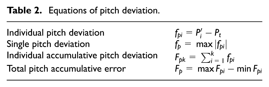
According to the definitions in related standards, the value of pitch deviations can be calculated through equations in Table 2.
Equations of pitch deviation.
Profile error
The profile error
In order to facilitate the measurement of the whole tooth profile, grid division of the tooth surface is needed. The number relates to the sample accuracy of tooth flank, while too much grid will take excessive measurement time. A grid of
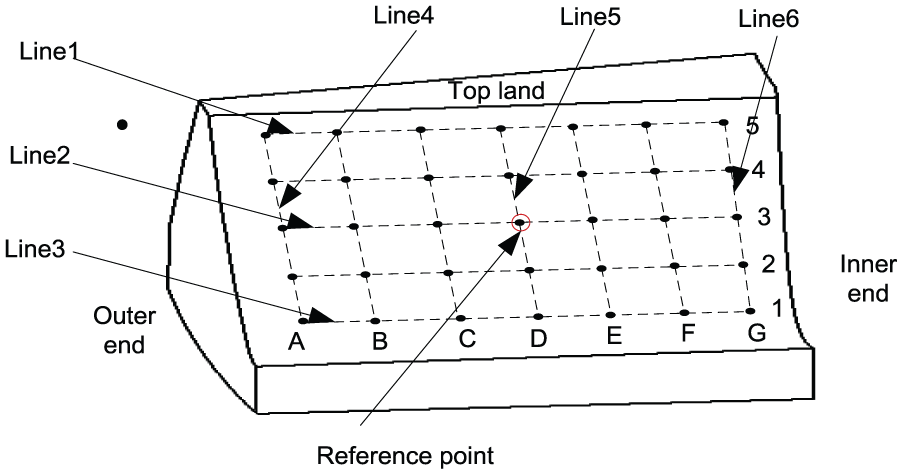
Positions of grid points on one tooth.
The positions of reference points on different flanks vary with the spatial pitch curve of curve-face gear, but the same is that the reference point is at the tolerance diameter and it is the midpoint of the grid. For curve-face gear, tolerance diameter is the sum of inner radius and outer radius of the curve-face gear. In order to cover the whole tooth profile, Z coordinate of the reference point is the same as the intersection point of pitch curve and tooth flank. A point can be defined on an axial plane of the curve-face gear with the Z coordinate and radius of reference point, and then, define a grid with this point as the center. Each grid point is projected by rotation around the curve-face gear axis onto the theoretical tooth flank, see Figure 7. Thus, theoretical coordinates of grid points on tooth flank (including reference points) can be derived with Z coordinate, radius, and equation of tooth surface easily.

Derivation of grid points.
The coordinates of actual measuring points were defined as the intersection of the normal vectors of the corresponding theoretical coordinates and the measured curve, as shown in Figure 8. Thus, in order to obtain the measured coordinates, the unit normal vectors should be worked out first. According to the equation of the surface of curve-face gear


Schematic representation of the calculation of profile errors.
Finally, the coordinate

where
Thus, the profile error

Calculation of deviations
The measurement coordinate system is established by the method introduced in section “Measuring of curve-face gear pair.” It is clear that the measurement coordinate system
As shown in Figure 9, z represents the shift amount along


Schematic representation of the coordinate systems.
The coordinate of measured points in design coordinate system can be expressed as follows

Pitch deviation
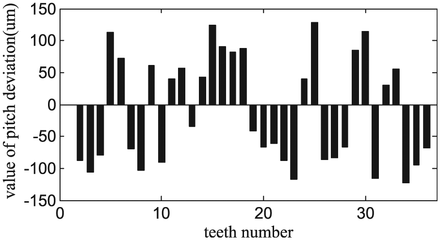
Based on the calculation method of pitch deviation presented in Table 2, the values of pitch deviations of the curve-face gear pair artifacts can be worked out with the revised coordinate data. The single pitch deviation of non-circular gear artifacts is shown in Figure 10. The single pitch deviation of curve-face gear artifacts is shown in Figures 11–13.

Pitch deviation of non-circular gear artifacts.

Pitch deviation of five-axis CNC machined curve-face gear artifacts.
Pitch deviation of additive manufactured curve-face gear artifacts.

Pitch deviation of composite machined curve-face gear artifacts.
Since there are not any measurement and accuracy standards for non-circular gear and curve-face gear, ISO 1328-1:2013 (cylindrical gears-ISO system of flank tolerance classification), ISO 17485:2006 (bevel gears-ISO system of accuracy), and GB/T 11365:1989 (accuracy of bevel and hypoid gears (in Chinese)) are referred to evaluate the accuracy grades of the gear pairs.
With reference to ISO 1328-1:2013, single pitch tolerance of non-circular gear shall be calculated using equation (15). Total cumulative pitch tolerance of non-circular gear shall be calculated using equation (16) as follows
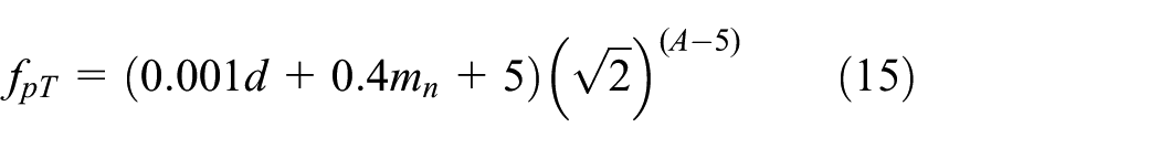

where d is the reference diameter; for non-circular gear, choose the sum of major axis radius and minor axis radius of pitch curve as d; and A is the number of the required tolerance grade. The pitch deviation tolerance of non-circular gear in this size is presented in Table 3.
Pitch deviation tolerance of non-circular gear.

So, values of pitch deviation and the corresponding accuracy grade of non-circular gear artifacts are presented in Table 4.
Accuracy grade of non-circular gear artifacts.

CNC: computer numerical control.
With reference to ISO 17485:2006, single pitch tolerance of curve-face gear shall be calculated according to equation (17). Total cumulative pitch tolerance shall be calculated according to equation (18)


where
Pitch deviation tolerance of curve-face gear.

CNC: computer numerical control.
Same as non-circular gear, values of pitch deviation and corresponding accuracy grade are presented in Table 6.
Accuracy grade of curve-face gear artifacts.

CNC: computer numerical control.
Pitch deviation beyond the maximum tolerance of grand 11.
Profile error
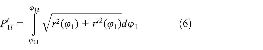
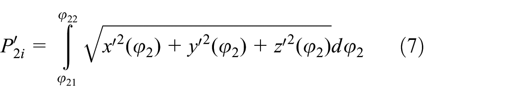
Similar to the pitch deviation, based on the calculation method of profile error introduced in equations (6)–(10), it is easy to work out the profile errors of curve-face gear artifacts with the revised coordinate data. One gear tooth is chosen as an example in this article. The profile errors on three curve-face gear artifacts are presented in Tables 7–9.
Profile error of five-axis CNC machined curve-face gear artifact.

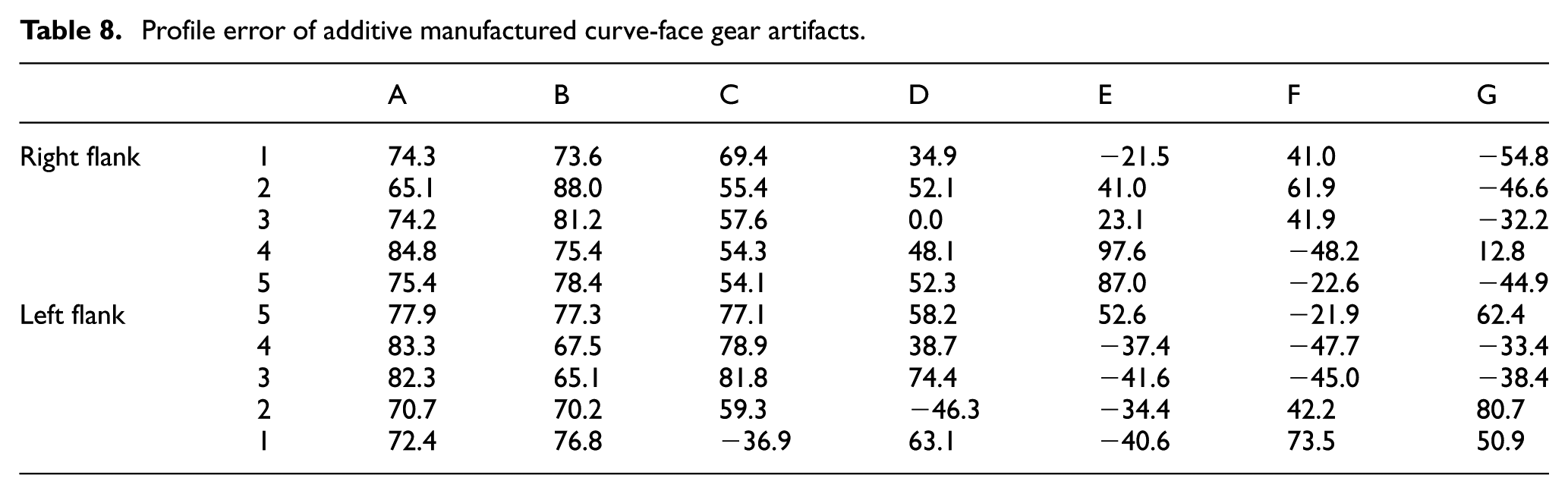
Profile error of additive manufactured curve-face gear artifacts.
Profile error of composite machined curve-face gear artifacts.
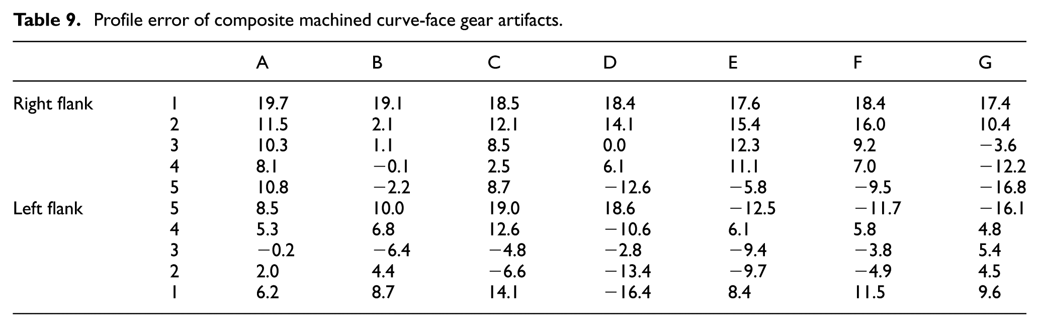
In comparison with the numerical results, a simplified graphical output can provide a better overview of the course of deviations across the tooth flank. So, a kind of three-dimensional (3D) graph output of profile errors is plotted, as shown in Figures 14–16. In these figures, the theoretical tooth flank is represented by the grid in plane, and the nodes of grid represent theoretical points on tooth flank. The measured points deviate from the grid nodes, and deviations are illustrated by line segments vertical to grid plane, where the length of line segment represents the value of deviation. Thus, the grid connected by measured points can reflect actual tooth flank.

3D graph output of five-axis CNC machined curve-face gear artifacts.

3D graph output of additive manufactured curve-face gear artifacts.

3D graph output of composite machined curve-face gear artifacts.
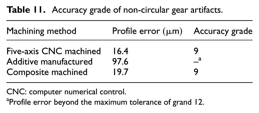
With reference to GB/T 11365:1989, profile error tolerance of curve-face gear is presented in Table 10. So, values of profile error and the corresponding accuracy grades of curve-face gear artifacts are presented in Table 11.
Profile error tolerance of curve-face gear.

Accuracy grade of non-circular gear artifacts.
CNC: computer numerical control.
Profile error beyond the maximum tolerance of grand 12.
For further analysis of profile error difference of curve-face gear processed by three methods, different parts of the tooth flank are selected for analysis. As shown in Figure 6, six lines are selected. Lines 1–3 are placed toe-to-heel, representing districts around tip, intermediate, and root. Lines 4–6 are placed root-to-tip, representing districts around outer flank, medial flank, and inner flank. Average profile errors of these lines are presented in Figures 17 and 18.
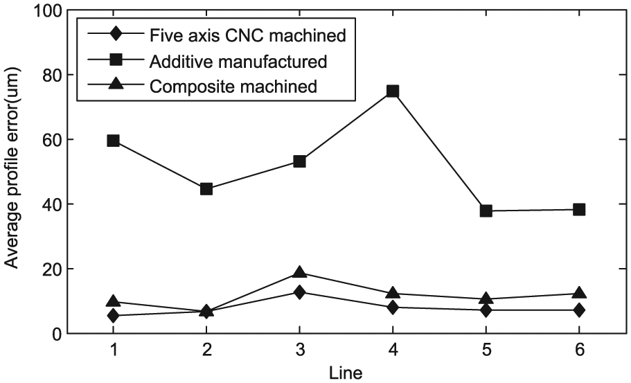
Average profile error of lines on right flank.

Average profile error of lines on left flank.
As can be seen from Figures 14–18, profile error of the curve-face gear processed by additive manufactured method is much larger than the other two methods; profile error of the curve-face gear artifact processed by composite machining method is slightly larger than the one processed by five-axis CNC machining. Since the tooth flank of curve-face gear is complex spatial surface, step effect will be produced in the process according to the basic principle of additive manufacturing. This leads to relatively large profile error in curve-face gear artifact processed by additive manufacturing. For composite machined curve-face gear artifact, accuracy is mainly guaranteed by five-axis CNC machining in the second step. The secondary clamping, which produces new error, leads to a slightly larger profile error than five-axis CNC machining.
Conclusion
In this article, a method based on gear measuring center has been developed to detect and evaluate geometric errors of curve-face gear artifacts processed by three different ways:
A method to find out the actual measured points that corresponds to a theoretical point has been put forward. By fitting the measured points into a curved surface, the normal vector of theoretical point intersects with the fitted curved surface, and the intersection can be regarded as the actual measured points.
Pitch deviations of curve-face gear pair artifacts processed by three methods are derived and accuracy grade of pith deviation is evaluated with reference to the accuracy standards for cylindrical gear and bevel gear.
Profile errors of curve-face gear artifacts are derived, 3D graph is plotted to provide a better overview of the course of deviations across the tooth flank, and accuracy grade is evaluated with reference to the accuracy standard for bevel gear.
Overall, geometric error of curve-face gear artifact processed by additive manufactured method is much larger than the other two methods because of step effect; and the geometric error of the curve-face gear artifact processed by composite machining method is slightly larger than the one processed by five-axis CNC machining owing to secondary clamping.
Footnotes
Academic Editor: Fakher Chaari
Declaration of conflicting interests
The author(s) declared no potential conflicts of interest with respect to the research, authorship, and/or publication of this article.
Funding
The author(s) disclosed receipt of the following financial support for the research, authorship, and/or publication of this article: This study is supported by the National Natural Science Foundation of China (51275537) and Chongqing University Postgraduates’ Innovation Project (CYS15008).