
Abstract
The CRTS I double-block ballastless track under the coupling effect of temperature and falling-shaft impact is more adaptable to actual operation. However, domestic and foreign research has only focused on either temperature or train loadings. In this study, the finite-element method was used to analyze the dynamic response of the double-block ballastless track structure. The results suggests that the displacement and acceleration characteristics of the ballastless track structure under different working conditions change significantly than no temperature gradient. Moreover, the vibration responses at the different working conditions under the impact excitation of a dropping wheelset show that. The findings of this study revealed that temperature has significant impact on falling-shaft which cannot be ignored, consequently it, paper provides referential information for the design, construction, operation and maintenance of the CRTS I double-block ballastless track structure under with large temperature difference.
Keywords
Introduction
The double-block ballastless track is mainly composed of rails, fasteners, track slabs and hydraulic supporting layers. The CRTS I double-block ballastless track is one of the main forms of ballastless track. Since the Type I double-block ballastless track is continuously poured, in areas with large temperature differences, the structure will have high-temperature swelling or low-temperature cracking. 1 The concrete structure of the ballastless track directly exposed to the atmosphere will deform under the influence of the external ambient temperature. After these deformations are constrained by the connection form of the track structure, the lower foundation, and the upper rail, the track structure will be subjected to periodic temperature effects stress.2,3 There are often various irregularities on the wheel tread and the top surface of the rail, such as longitudinal unevenness of the track, corrugated wear on the top surface of the rail, and wheel flat scars. When the train passes through the uneven track, the wheel tread may be the same as the rail top. When the wheel is detached from the surface, because the primary spring of the vehicle bogie is in a compressed state, the compression spring will bounce the wheel to the rail surface, causing wheel-rail impact. Based on this, the falling axle excitation can be used to make the wheel set fall freely from a certain height, form a vertical impact on the rail surface, cause the track structure to vibrate, and simulate the actual impact between the wheels and the rail when the train is running to determine the dynamics of the track structure Parameters and vibration characteristics. 4
Wang 5 used finite element software to establish a unit slab ballastless track structure to calculate the temperature warping rules of the slab, and the whole calculation result is static analysis.
In the natural environment, the internal and surface temperatures of concrete structures vary with time, thereby causing temperature deformation. When deformation is obstructed by the constraints of the structure itself, temperature loading is generated.6,7 Moreover, large temperature stresses inside the track structure can develop due to variations in the environmental temperature, which, in turn, result in cracking and warping. 8 Therefore, temperature loading is a major problem that needs to be addressed in order to ensure the safety of a CRTS I double-block ballastless track. 9
During the operation of a high-speed railway, the temperature-gradient load significantly influences the mechanical characteristics of a ballastless track. 10 Cracking, upturning and arching can frequently occur due to temperature- and train-dynamic loadings, thereby seriously affecting track performance and increasing maintenance costs. 11 How the falling shaft affects concrete components or railway structures has been studied extensively for many applications. However, little attention has been given to the temperature effects on dynamic response. 12 Therefore, it is necessary to study the dynamic response and vibration-transfer rule of a double-block ballastless track under the coupling effects of temperature and falling-shaft impact loadings. The findings of this study can provide valuable information for the design, construction and maintenance of a CRTS I double-block ballastless track structure.
Several authors have researched research on the marked effects of either temperature or train loading on the in-service operations and design life of a track structure.
Based on the theory of thermodynamics, Ou et al. 13 established the one-dimensional heat-conduction equation of the temperature field of a ballastless track. By using ANSYS software, Fu et al. 14 studied the temperature-field evolvement of a ballastless track with a two-dimensional finite-element model. Moreover, Trong et al. 15 investigated the effect of temperature gradients on the dynamic response of train-track systems. In China, until recently, the majority of domestic research on the mechanical effects of a track structure under temperature loading has only considered one-dimensional vertical temperature loadings, by predominantly establishing static models. Relatively scanty researches has been conducted concerning the dynamic response and vibration-transfer law of a track structure under the coupling action of a three-dimensional temperature load and dynamic force. This is a major limitation, since such a condition is consistent with respect to the actual temperature-field distribution of an in-service structure. 16 In order to establish a rational numerical-analysis method for the CRTS I double-block ballastless track structure under an impact loading, a falling-weight impact test was conducted.17,18
To reflect the dynamic response and vibration-transfer law of a double-block ballastless track under the coupling action of the train-dynamic and temperature loads, a three-dimensional temperature and falling-shaft finite-element model was established based on the following datasets: the temperature-monitoring data of the subgrade section of the Jingzhang railway and the double-block ballastless track structure falling-shaft impact test data from the National Engineering Laboratory of High-Speed Railway Construction Technology at Central South University. 19
Using this model, Lei 20 computed the vertical random vibration of vehicle/track system under different railway line orders and different train speeds. Analyses of system responses were performed in the time and frequency domains.
Xiang 21 puts forward spatially coupling vibration analysis model of train-track time-variant system.
In order to analyze the influence of temperature deformation on the train running performance of long-span steel box-girder tied-arch bridge, a bridge of such type with a span of 96 m span was identified as a case for study by Bangwu. 22 They built the dynamic analysis model of the bridge and investigated the natural vibration characteristics. The results show that the effect of temperature deformation on the dynamic response of bridge is not significant. However, they did not study the dynamic response of temperature loads to the track structure.
Xuan 23 established a three-dimensional(3D), finite element model of the track-subgrade system, with the aid of ANSYS for dynamic response of ballastless track subgrades bearing vehicle dynamic loads was performed, but temperature load was not considered.
Zhu 24 researched on the damage characteristics of double-block ballastless track bed slab under temperature and vehicle dynamic loads. However, the focus of the study was not to obtain the dynamic response of the track structure.
Yang 25 established vehicle track-subgrade vertical coupled dynamic model in the frequency domain. The random vibration responses and transfer characteristics of the double-block ballastless track and subgrade system under loading of running high-speed trains were analyzed, but the neglected temperature load was neglected.
Zeng 26 studied influence of track line environment on the temperature field of a double-block ballastless track slab. The horizontal and vertical temperature gradients in high latitudes and coastal areas were found to be more detrimental than that in the low latitudes or inland areas. However, they neglected dynamic response analysis.
Cuiying 27 established a damage model of double-block ballastless track and high-speed train system with slab-upwarp. The calculation program of the model was compiled and verified by FORTRAN.
Wang 5 used finite element software to establish a unit slab ballastless track structure to calculate the temperature warping rules of the slab, and the whole calculation result is static analysis.
In order to establish a rational numerical-analysis method for the CRTS I double-block ballastless track structure under an impact loading, a falling-weight impact test was conducted.17,18
To reflect the dynamic response and vibration-transfer law of a double-block ballastless track under the coupling action of the train-dynamic and temperature loads, a three-dimensional temperature and falling-shaft finite-element model was established based on the following datasets: the temperature-monitoring data of the subgrade section of the Jingzhang railway and the double-block ballastless track structure falling-shaft impact test data from the National Engineering Laboratory of High-Speed Railway Construction Technology at Central South University.
Temperature load and impact model of a double-block ballastless track structure
Temperature effect
The temperature field of a double-block ballastless track structure has a nonlinear distribution. 28 Accordingly, it is critical to determine the fixed time, explore the spatial–temperature distribution characteristics and obtain the temperature-field function. 29 According to the relevant specifications in China, the maximum vertical positive and negative temperature-gradient values of a ballastless track slab are 90 and −45°C·m−1, respectively. 11 There are no specific regulations with respect to the lateral temperature gradient. Based on the analysis of the temperature field of the Beijing-Zhangjiakou railway under natural conditions, the maximum lateral positive, and negative temperature gradients of a track plate are 5.5 and −4°C·m−1, respectively, and the maximum vertical positive and negative temperature gradients are 60 and −30°C·m−1, respectively. For this study, the temperature distribution of a double-block ballastless track structure in Huai’an County at 1 p.m. on 6 July 2018 is selected. The cross-section of a track slab is placed into the plane coordinate system, which extracts the temperature data and generates a three-dimensional diagram, as shown in Figure 1(a).

Three-dimensional distribution diagram of cross-section temperature of track slab.
Space–temperature function is defined here, as shown in equation (1):

where T (x,y) refers to the temperature function related to the plane coordinates, representing the width and height of the track bed, and the value range is 0–2800 and 0–260 mm. While a, b, c, d, e, and f are undetermined coefficients.
Equation (1) was used to fit the data; the numerical model was obtained as follows:
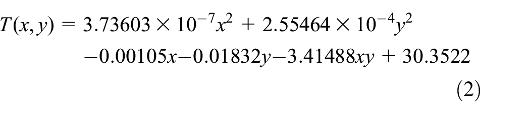
The x- and y-coordinates are substituted into the equation to generate a graph, as shown in Figure 1(b).
In essence, by comparing (a) and (b) in Figure 1, it is evident that the fitted data are consistent with the measured data. Furthermore, the goodness-of-fit analysis of the two groups suggests that R2 is 0.98846. Since this value is higher than 0.95, the model is accurate and reliable.
Finite-element model: Temperature and falling-shaft
Finite-element analysis is used to simulate physical systems through mathematical approximation. 30 By using ABAQUS software for a CRTS I double-block ballastless track, the geometric structure, physical, and loading conditions were simulated. 31 The track slab has a thickness of 260 mm and a width of 2800 mm; 32 the support layer is 300 mm thick and 3400 mm wide. The wheelset was simplified into an analytical rigid body with a mass of 1250 kg.33,34 The fastener is hinged, with a stiffness of 30 × 103 kN·mm−1 and a damping of 0.05 kN s mm−1. 35 Due to the short impact time of the load, only the first 0.05 s was used for calculation. 36 The physical parameters are shown in Table 1.
Physical parameters of each structure of CRTS I double-block ballastless track.

The loading mode consists of a vertical dynamic load and a three-dimensional distributed temperature load. The wheelset impacts the rail at a height of 25 mm, and the gravity acceleration is 9.8 m·s−2. 37 The space–temperature function is adopted for the temperature load. The finite-element model with respect to the temperature and falling-shaft impact loadings of the double-block ballastless track structure was established and consist of wheel, rail, sleeper, and track-bed, as shown in Figure 2.

Double-block ballastless track structure temperature-falling shaft impact finite-element model.
Model verification
Test method
Relying on the National Engineering Laboratory of High-Speed Railway Construction Technology of Central South University, the full-size model of a double-block ballastless track structure was established, and the experimental research with respect to its vibration characteristics under the action of a falling shaft was also carried out, as shown in Figure 3. The drop shaft in Figure 3(a), weighs 12t, and can be automatically controlled to achieve realizes different drop shaft heights. Figure 3(b) shows the layout diagram of acceleration measuring points in the drop test. The blue dot in the figure represents the rail acceleration measuring point, the yellow dot in the figure representing sleeper acceleration measuring points, and the red dot in the figure represents track-bed acceleration measuring point.

(a) Falling-shaft device (unit: mm) and (b) top view and cross section size of CRTS I double-block ballastless track structure (mm).
The analysis of the vibration and attenuation characteristics of the track structure is evaluated based on the falling-shaft test method established by the Japan Railway Technology Research Institute. This method mainly tests the dynamic response of the various components of the track structure under the wheel impact, and can better reflect the dynamics of the track structure characteristic. During the test, the wheelsets were used to impact the rail in free fall under seven working conditions of 5, 10, 15, 20, 25, 30, 35 mm. On the one hand, wheel and rail impact time is obtained by experiment. On the other hand, by testing the vibration acceleration of each component of the track structure, vibration transmission and shock attenuation performance of the track structure are analyzed. The acceleration sensors are orderly arranged in the nearby position of the wheel landing point, and the acceleration sensor ranges are 1000, 200, and 5 g, respectively.
Different landing heights will take the landing 10 times, taking the average of the maximum and minimum acceleration.
Model-Test verification
Comparisons between the model at each measurement point and the experimental acceleration data are shown in Figure 4. It is worth noting that positive acceleration represents the direction of acceleration vertically upward, and negative acceleration represents the direction of acceleration vertically downward.

Comparison between model and test data.
It can be seen from Figure 4 that whether it is rail, sleeper or track-bed, their acceleration increases with the drop height of the falling shaft for model measuring points and test points. The acceleration value of the track slab under the load is relatively small, due to external interference that affects it. Therefore, compared with rail and sleepers, the fit of the track slab is slightly lower.
As shown in Figure 4, the structural model data are, in essence, consistent with the experimental data. To compare similarities, the percentage of the mean distance in the total weighted mean of the two data sets was used. 38 The measuring point of the track slab was 13.17%, the rail measuring point was 9.83% and the sleeper measuring point was 0.77%. Therefore, the model has strong adaptability with respect to simulating a track structure under natural conditions.
Model Condition
According to the temperature-field distribution during train operation and referring to the limit temperature gradient outlined in the specifications, in order to obtain the dynamic response and transfer law of a falling shaft with respect to the track structure under seven working conditions outlined below were obtained.
(1) No temperature: Vertical temperature gradient: 0°C·m−1. Lateral temperature gradient: 0°C·m−1.
(2) Working condition 1: Vertical temperature gradient: 70°C·m−1. Lateral temperature gradient: 4°C·m−1. The initial temperature is 25°C, and the fitting function is as follows:

(3) Working condition 2: Vertical temperature gradient: 90°C·m−1. Lateral temperature gradient: 5°C·m−1. The initial temperature is 25°C, and the fitting function is as follows:

(4) Working condition 3: Vertical temperature gradient: 120°C·m−1. Lateral temperature gradient: 6°C·m−1. The initial temperature is 25°C, and the fitting function is as follows:

(5) Working condition 4: Vertical temperature gradient: −20°C·m−1. Lateral temperature gradient: −4°C·m−1. The initial temperature is 30°C, and the fitting function is as follows:

(6) Working condition 5: Vertical temperature gradient: −45°C·m−1. Lateral temperature gradient: −5°C·m−1. The initial temperature is 30°C, and the fitting function is as follows:

(7) Working condition 6: Vertical temperature gradient: −75°C·m−1. Lateral temperature gradient: −6°C·m−1. The initial temperature is 30°C, and the fitting function is as follows:

The above multi-dimensional temperature-field load is substituted into the coupled model (i.e. the temperature-falling-impact model) of a double-block ballastless track structure, and the finite-element analysis (and calculations) were conducted.
Acceleration response of the various components of a CRTS I ballastless track structure under the coupled action of temperature load and falling-shaft impact
Comparative analysis of the time-varying laws of vibration of the rail, sleeper and track-slab
The acceleration changes of the rail, sleeper and track-slab under seven working conditions were obtained using the model, and the time-varying laws of vibration under each working condition were further analyzed with respect to measurement point g1, s1, and d1, as are shown in Figures 5 to 7. It is worth noting that time-varying refers to the law that the observed trend of acceleration at the measuring point changes with time.

Fluctuation diagram of g1 vertical acceleration under various working conditions.

Fluctuation graph of s1 vertical acceleration under various working conditions.

Fluctuation graph of d1 vertical acceleration under various working conditions.
It can be seen from Figure 5(a) to (g) that the vertical acceleration fluctuation period of the rail is 0.012 s under the seven working conditions.
Compared with the no temperature working condition, the maximum and minimum vertical acceleration values of the rail under the applied vertical temperature and the lateral temperature both increase, but the maximum and minimum vertical acceleration of the rail when the vertical temperature and the lateral temperature are both positive values is greater.
It can be seen from Figure 6(a) to (g) that the vertical acceleration fluctuation period of the sleeper is 0.012 s under the seven working conditions.
When the vertical temperature gradient and the lateral temperature gradient are both positive temperature gradients, the vertical downward acceleration change amplitude of the sleeper is greater than the vertical temperature gradient and the lateral temperature gradient are both negative temperature gradients, the vertical upward acceleration change amplitude is less than the vertical temperature gradient and the lateral temperature gradient are both negative temperature gradient.
It can be seen from Figure 7(a) to (g) that the vertical acceleration fluctuation period of the slab is 0.013 s under the seven working conditions.
When the vertical temperature gradient and the lateral temperature gradient are both positive temperature gradients, the vertical upward acceleration change amplitude of the track slab is greater than the vertical temperature gradient and the lateral temperature gradient are both negative temperature gradients, and the vertical downward acceleration change amplitude is less than the vertical temperature gradient and the lateral temperature gradient are both negative temperature gradients.
Comparative analysis of the vertical acceleration response of the rail, sleeper, and track-slab
Using the finite element model, the extreme values of rail, sleeper and track-slab acceleration under seven working conditions are shown in Figure 8.

Maximum and minimum vertical acceleration under seven working conditions.
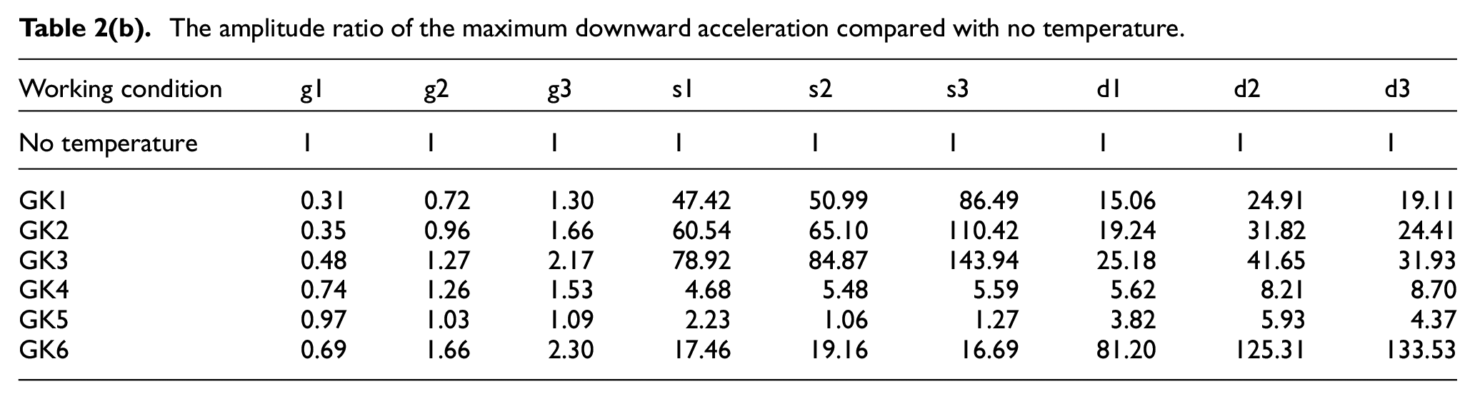
The numbers in Table 2 are obtained by comparing the acceleration of the six working conditions measuring point with that under no temperature condition. The corresponding value of the measuring point under the no temperature condition is 1.
The amplitude ratio of the maximum upward acceleration compared with no temperature.

The amplitude ratio of the maximum downward acceleration compared with no temperature.
As shown in Figure 8, compared with the working condition without a temperature gradient, with the rise of positive temperature gradient, the upward acceleration of rail, sleeper, and track-slab increases significantly, and the upward acceleration of the measuring point far away from the drop hammer point is largest. Similarly, the results are consistent under a negative temperature gradient.
As shown in Tables 2(a) and 2(b), compared with the working condition without a temperature gradient, under three working conditions, including GK1, GK2, and GK3, when the vertical and horizontal temperature gradients are positive, the upward maximum acceleration of track-slab is respectively 140.70, 179.52, and 232.20 times larger than the original, while the downward maximum acceleration of sleeper is respectively 86.49, 110.42, and 143.94 times larger than the original, respectively. Under three working conditions: GK4, GK5, and GK6, when the vertical and horizontal temperature gradients are negative, the upward maximum acceleration of sleeper is respectively 44.48, 21.72, and 133.46 times larger than the original, while the downward maximum acceleration of track-slab is respectively 8.70, 4.37, and 133.53 times larger than the original, respectively.
In conclusion, at the rail, sleeper and track-slab measuring points, the upward acceleration increases significantly after temperature loading is applied. On the one hand, when the surface temperature of the track slab was higher than the internal temperature, the downward acceleration of sleeper and the upward acceleration of track-slab increased significantly; on the other hand, when the vertical and horizontal temperature gradients are negative, the upward acceleration of sleeper and the downward acceleration of track-slab significantly increased.
Frequency domain analysis of the law of vertical transmission along the track
The vibration measurement can be carried out according to the code Mechanical Vibration and Shock-Evaluation of Human Exposure to Whole-body Vibration (ISO 2631-1-1997) 39 and the Chinese code Measurement Method of Environmental Vibration of Urban Area (GB/T 13441-2007) 40 and the Chinese code Measurement method of environmental vibration of urban area (GB10071-88). 41 According to Organization IS. ISO 2631-1 42 and Standardization Administration of China, 43 the vibration level insertion loss is used to evaluate the vibration reduction effects. The vibration acceleration level (VAL) is calculated using equation (1):

Where a is the vibration acceleration RMS, a0 is reference acceleration, a0 = 10−6m/s2.
The VLZ is the vertical ground vibration acceleration level obtained by the WK weighting factor correction. The VAL is calculated using equation (2):

Where VALi is the i-th vibration acceleration level, WKi is the i-th weighting factor, n is the number of 1/3 octave calculation points.
The insertion loss is the difference between the vibration levels with different vibration control measures, which is defined as equation (3):


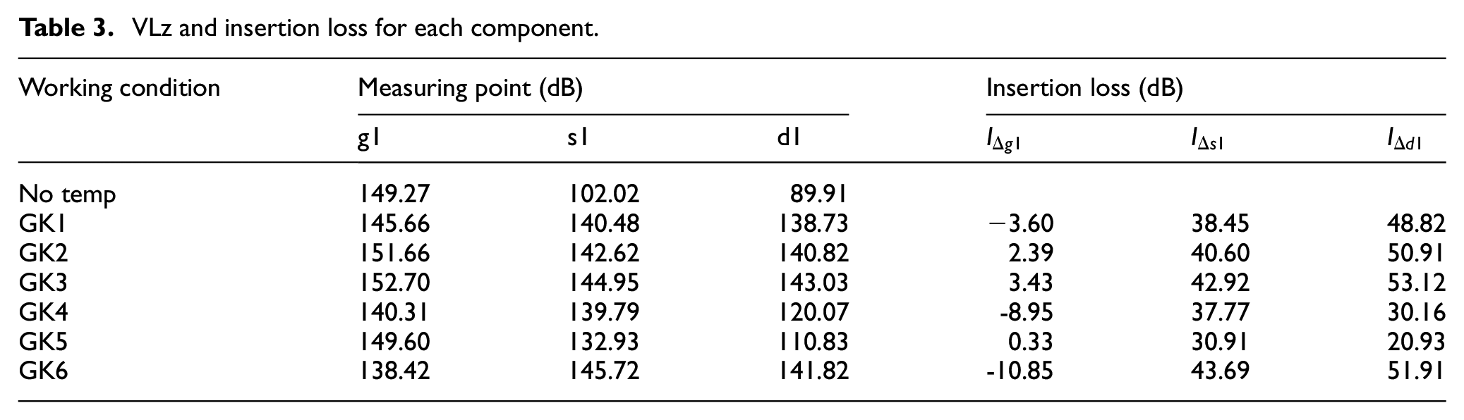
The VLz of each track structural component is shown in Table 3. The difference between the seven working conditions in the rail is small, but the maximum insertion loss at an applied positive temperature gradient on the sleeper and the track slab is 42.92 and 53.12 dB, respectively. Compared with no temperature load, the VLz of sleeper and track slab under the maximum positive temperature gradient increase by 42.08% and 59.08%, respectively. The VLz of sleeper and track slab under the maximum negative temperature gradient increased by 42.83% and 57.74%, respectively. The average insertion loss that at an applied negative temperature gradient on the rail is smaller than no temperature condition indicating that negative temperature gradient applied to the track structure can attenuate the impact vibration and reduce the rail vibration.
VLz and insertion loss for each component.
Displacement response of track structures under the coupled action of temperature load and falling-shaft impact
Comparative analysis of the time-varying laws of vertical displacement of the rail, sleeper, andtrack-slab
The vertical displacement changes of the rail sleeper and track-slab under seven working conditions were obtained using the model, and the time-varying laws of vertical displacement under each working condition were further analyzed with respect to measurement point g1,s1 and d1. Again, the time-varying laws of vibration with three measuring points under working conditions 2 were selected for illustration, as shown in Figure 9.

Time-varying laws of vertical displacement fluctuation under working condition 2.
As shown in Figure 8, the displacement-fluctuation periods of g1, s1, and d1 under working condition 2 are 0.01, 0.012, and 0.015 s, respectively.
Comparative analysis of the vertical displacement of the rail, sleeper, and track-slab
Using the finite element model, the extreme values of vertical displacement under each working condition are shown in Figure 10.

Maximum vertical upward and downward displacement under various working conditions.
As shown in Figure 10, compared with the working condition without any temperature gradients, under working conditions 1, 2, and 3, as vertical and horizontal positive temperature gradients increase, the vertical downward displacement of rail and track-slab decreases gradually, however, the vertical upward displacement of rail and sleeper increases gradually. Under working conditions 4, 5, and 6, as vertical and horizontal negative temperature gradients increase, while the vertical downward displacement of rail and sleeper is decreasing gradually.
As shown in Table 4, under various temperature loads, the downward displacement of rail is much larger than the upward displacement. Moreover, under working conditions 1, 2, and 3, the downward displacement of the rail is respectively 0.96, 0.95, and 0.93 times larger than the original, while the downward displacement of track-slab is respectively 13.41, 16.95, and 21.89 times larger than the original. Alternatively, under working conditions 4, 5, and 6, the downward displacement of rail is respectively 1.01, 1.00, and 1.04 times larger than the original, while the downward displacement of sleeper is respectively 5.36, 2.18, and 13.47 times larger than the original. In addition, when the surface temperature of the track slab is higher than the internal temperature, the downward displacement of sleeper, and the upward displacement of track-slab remain 0 mm. However, the upward displacement of sleeper remains 0 mm when the surface temperature of the track plate is lower than the internal temperature.
Maximum and minimum vertical displacement under various working conditions (unit: mm).

Comparative analysis of maximum principal stress of track-Slab under the coupled action of temperature load and falling-shaft impact
Due to the strength of the rail and the prefabricated double block sleeper, cracking does not easily occur. However, the track-slab is cast-in-place and its ultimate tensile strength is relatively low. Therefore, the maximum principal stress of the track -slab in the above working conditions should be considered.
In order to more intuitively explore the changing rule of the maximum principal stress at the measuring point of track-slab when the lateral temperature gradient and vertical temperature gradient gradually increase, the maximum principal stress at different working conditions was calculated and tabulated in Table 5.
The maximum of the maximum principal stress under each working condition.
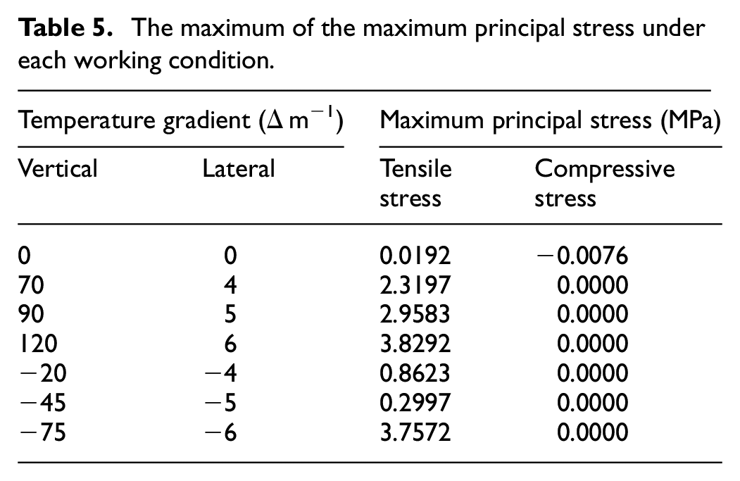
As shown in Table 5, compared with the working condition without any temperature gradient, under working conditions 1, 2, and 3, when the vertical and horizontal temperature gradients are positive, the tensile stress increases respectively by 11981.77%, 15307.81%, and 19843.75% larger than the original. Under working conditions 4, 5, and 6, when the vertical and horizontal temperature gradients are negative, the tensile stress respectively increases by 4391.15%, 1460.94%, and 19468.75% larger than the original.
Under the conditions 3, 4, and 7, the tensile stress of track-slab exceeds the standard tensile strength value of C40 concrete, so the track-slab cracks. 41 Therefore, special attention should be paid to the construction and operation of track-slab when building railway in the area of large temperature difference.
Conclusion
From the study, the following conclusions can be drawn:
The model established in this study has high adaptability with respect to actual working conditions, which have been essentially ignored in associated research.
After the application of temperature load is applied, the acceleration at each measurement point of the double-block ballastless track increases significantly. When the surface temperature of the track slab is higher than the internal temperature, the maximum upward acceleration of track-slab increases significantly. With the rise of positive temperature gradient, the upward and downward acceleration of rail, sleeper and track-slab increases significantly, and the upward acceleration of the measuring point farthest away from the drop hammer point been the maximum. When the surface temperature of the track slab is higher than the internal temperature, the maximum upward acceleration of rail, sleeper and track-slab increases by 3.85, 97.02 and 232.20 times the original. Also, when the surface temperature of the track slab is lower than the internal temperature, the maximum upward acceleration of rail, sleeper and track-slab increases by 2.16, 133.46, and 21.88 times the original.
After the temperature load is applied, the difference between the seven working conditions in the rail is small, but the insertion loss of sleeper and track-slab increases significantly, which indicates that temperature has a great influence on the vibration of sleepers and track-slab, so the temperature load must be considered when studying the vibration of sleepers and track-slab. Compared with no temperature load, the VLz of sleeper and track slab under the maximum positive temperature gradient increase by 42.08% and 59.08%, respectively. The VLz of sleeper and track slab under the maximum negative temperature gradient increased by 42.83% and 57.74%, respectively.
Upon application of temperature load is applied, the displacement at each measurement point of the double-block ballastless track changes significantly. When the surface temperature of the track slab is higher than the internal temperature, the maximum downward displacement of the rail decreases by 93.3%, the upward displacement of the track-slab and the downward displacement of the sleeper are 0 mm, while the maximum upward displacement of the rail and sleeper increases significantly, to 3.9 and 145.7 times the original, respectively. When the surface temperature of the track slab is lower than the internal temperature, the maximum downward displacements of the rail, sleeper and track slab increased significantly, to 1.04, 13.5, and 5.08 times the original, respectively. However, the upward displacement of the sleeper remained 0 mm.
Compared with no temperature gradient, the tensile stress of the track-bed increases greatly after applying the temperature gradient, and this cannot be ignored, since it is not possible to avoid construction in high temperature of summer or low temperature of winter.
Footnotes
Handling Editor: James Baldwin
Declaration of conflicting interests
The author(s) declared no potential conflicts of interest with respect to the research, authorship, and/or publication of this article.
Funding
The author(s) disclosed receipt of the following financial support for the research, authorship, and/or publication of this article: This work was supported by the High-speed Railway Joint Fund of National Natural Science Foundation of China (Grant U1734208), the Major Program of National Natural Science Foundation of China (Grant 11790283), Hunan Provincial Natural Science Foundation of China (Grant 2019JJ40384).
Data availability statement
All data, models, and code generated or used during the study appear in the submitted article.