
Abstract
This paper proposed a hierarchical multi-level model to study the crystallographic texture induced mechanical anisotropy of AA3104-H19 aluminium sheet from mesoscale to continuum scale. In the mesoscale, full-field crystal plasticity finite element method (CPFEM) was used to provide both in-plane and out-of-plane yield stresses and plastic potential points in various deformation modes. In the continuum scale, these materials sampling points were used to determine the parameters of two phenomenological yield functions (Yld2000-2d in plane stress space and Yld2004-18p in 3D stress space) using associated flow rule (AFR) and non-associated flow rule (non-AFR). The results indicate that higher accuracy obtained by Yld2000-2d and Yld2004-18p yield functions associated with non-AFR in comparison with AFR. These phenomenological models were successfully implemented into finite element (FE) code using an explicit integration scheme to simulate sheet metal forming. It is found that the 3D Yld2004-18p model involved with both in-plane and out-of-plane anisotropies is superior to 2D Yld2000-2d model which only accounts for in-plane anisotropy.
Keywords
Introduction
Aluminium alloy sheets generally exhibit a considerable mechanical anisotropy due to the strong crystallographic texture induced by heavy cold rolling reductions. This property has a significant influence on the sheet metal forming operations, for example, the final shape and spring-back level of the formed part, reaction force and wear of tooling system. Therefore, the investigation of mechanical anisotropy is important for sheet metal forming.
In conventional phenomenological approach, the yield surface plays a pivotal role in describing the plastic mechanical anisotropy. Mathematically, the shape of yield surface is determined by a convex function using a set of parameters which obtained by fitting the yield stress and plastic potential points in various stress states provided by well-designed physical tests. 1 The phenomenological approach shows strong robustness for the simulation of sheet metal forming, and high computational efficiency on plane-stress problems. However, it is hard to characterise the out-of-plane anisotropy of sheet metals via physical tests. Thus, early yield function is only used for plane-stress problems, for example, the widely used Yld2000-2d plane stress yield function.2,3 To obtain the mechanical anisotropy in 3D stress case, Barlat et al. proposed a convex yield function named Yld2004-3D 4 in which the out-of-plane mechanical anisotropy is determined by an analytical crystal plasticity method so-called TBH. 5 This yield function has been successfully implemented into FE code and shown an accurate earing prediction of strong textured AA2090-T3 in deep drawing process. 6 However, the assumption of the analytical TBH crystal plasticity (CP) model cannot satisfy the stress equilibrium and compatibility simultaneously. 7 The TBH model showed great deviation in the prediction of directional yield stresses and plastic potentials against experimental tests. 8
In classic flow theory of plasticity, the associated flow rule (AFR) is generally employed in the yield function to describe the yielding and plastic potential for strain increment simultaneously. However, the plastic potentials are difficult to associate with the yield surface when describing a highly anisotropic material with an identical function.9–11 Therefore, the non-associated flow rule (non-AFR) can be applied to overcome this limitation which eliminates the constraint of the correlation between yield surface and plastic potential.12–14 In this flow theory, two independent functions are used to determine the yielding and plastic potential, respectively. Various combinations of phenomenological yield functions associated with non-AFR were studied by previous works. For instance, the yld2000-2d 2 and Hill48 15 yield functions using non-AFR were superior to the conventional AFR with respect to the fitting of mechanical anisotropy for AA2090-T3, AA5042, AA5754-O and AA5182 sheets.10,11,16,17 The non-AFR also showed an adequate capability in description of anisotropic and kinematic hardening behaviour of various strong textured sheet metals.11,16–20 However, these previous works were based on the phenomenological method using plane stress assumption which were relied on the physical tensile experiments and only determines the in-plane mechanical anisotropy.
Recently, the full-field CPFEM was developed to simulate the polycrystalline aggregates under various loading conditions which not only accounted for the crystallographic texture but also incorporated with additional morphological information, for example, the grain size, boundary and orientation. Therefore, the local grain interaction and intra-grain inhomogeneities are simulated in the crystal plasticity modelling.7,21 Compared with analytical CP model, the main advantages of full-field CPFEM were reflected in their robust solution to solve polycrystal micromechanics problems and convergence under complicated boundary conditions. Moreover, CPFEM considered inter-grain and intra-grain micromechanical interactions in the physics of crystal mechanics. 22 However, the main drawback of CPFEM was associated with high computational costs when fine meshes are assigned to construct a high resolution representative volume element (RVE).21,23,24
Since the full-field CPFEM showed a good capability in the description of micromechanics of polycrystal under external loads, this advanced method can successfully reproduce the crystallographic texture induced mechanical anisotropy of as-rolled sheet metal observed by experimental uniaxial tensile tests in various material directions.7,8,25–29 Furthermore, CPFEM can be used to predict the out-of-plane anisotropy due to no constraint on deformation mode. This property was difficult to be obtained by physical tests due to the thin wall structure of sheet metal. These advantages enabled a large number of in-plane and out-of-plane yield stresses and plastic potentials points to be predictable.
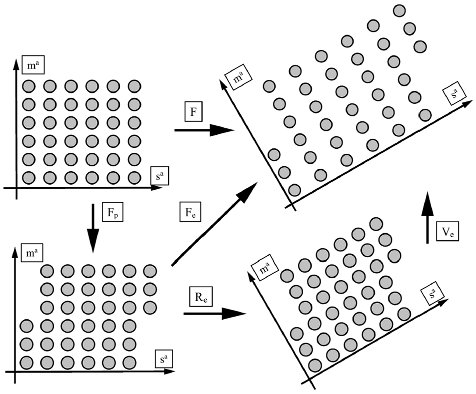
To comprehensively study the plastic behaviours of strong textured aluminium alloy sheet, a hierarchically structured multi-scale constitutive model (from mesoscopic crystallographic scale to macro continuum scale) was developed to accurately describe the in-plane and out-of-plane yielding and plastic potentials under multi-axial loading conditions in this study. In this method, an RVE of the strong textured AA3104-H19 aluminium alloy was constructed to predict the mechanical anisotropy of polycrystalline aggregates under various in-plane and out-of-plane loading conditions using full-field CPFEM. These data were employed to determine the parameters of the phenomenological yield and plastic potential functions using non-AFR. This hierarchically structured model (please see Figure 1) has been successfully implemented into FE code and can be readily adapted for forming simulations of different aluminium sheets.

The schematic configuration of the multiscale and multiphysics CP modelling framework used for sheet metal forming simulations.
Crystal plasticity modelling
Constitutive formulations
The crystal kinematics of isothermal finite deformation describes the process

where

where the elastic deformation
The table of nomenclature used in this study.

The schematics of lattice deformation for two intermediate configurations between the undeformed and the current configurations governed by elastic stretching, rotation and the motion of dislocation.
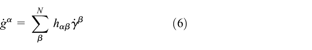
The crystal kinematics of finite deformations requires an constitutive equation for the time rate of change of deformation gradient

where

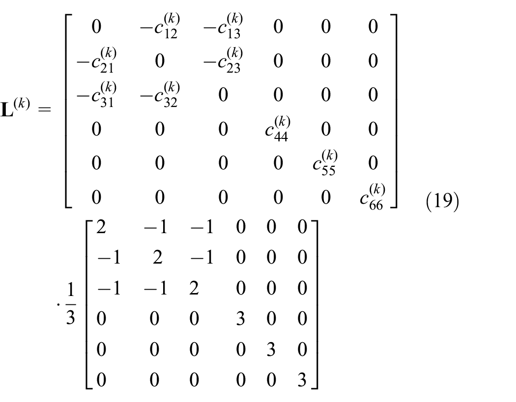
where

where
where
where
To implement the crystal plasticity constitutive model into the numerical solver, the applied shear stress

where

where

Preprosessing
To build the full-field CPFEM model, a cube of dimension 1 mm3 was considered as the RVE, and a periodical Voronoi tessellation of 500 randomly placed seeds was used to generate 500 random grains using the open-source polycrystal generation and meshing software Neper. A total of 500 crystallographic orientations generated in accordance with orientation distribution functions (ODFs) which is calculated from the electron backscatter diffraction (EBSD) measurement. These grain orientations were randomly assigned to the individual grain cell of RVE. Zhang et al. 7 show the low root mean squared deviations (RMSD) between the reconstructed ODFs and experimentally determined ODFs, indicating that 500 crystallographic orientations are enough to represent the texture of materials.
As stated above, the cubic RVE with the crystallographic texture was used to perform the virtual uniaxial tensile tests and to obtain the uniaxial yield stresses and plastic potentials in various directions for the identification of various yield functions. In addition, the virtual plan-strain, pure shear and equibiaxial tensile tests were performed to obtain the anisotropic properties in biaxial stress states. To reproduce the experimental stress state in virtual tests, periodic boundary conditions applied on the faces of the RVE.
To perform the virtual tensile tests in various in-plane and out-of-plane directions with respect to the RD, applying periodic boundary conditions in loading direction was inconvenient to calculate the r-values due to the non-rectangular shapes of the deformed RVE. Therefore, the boundary conditions of the RVE were remain constant in space, while rotating the Euler angle of 500 grains is a equivalent method as rotating the loading direction for the cubic-orthorhombic FCC.7,8
Phenomenological plasticity constitutive model
Yield function
The crystal plasticity method gives the essential understanding of plasticity in metal materials. However, this method requires large computational costs for the large-scale engineering problem. The phenomenological plasticity method is widely used to describe the yielding and plastic deformation of materials due to its simple expression and user-friendly implementation in FE modelling. An advanced phenomenological plane stress anisotropic yield function so-called Yld2000-2d proposed by Barlat et al.
2
gained considerable popularity mainly because of its accurate prediction of yield stresses and r-values for various strong textured aluminium alloys. This yield function is based on multiple linear transformations of two unconditionally convex functions

where

where the exponent


where the linear transformations were defined as:


The Yld2000-2d has shown the adequate flexibility for the calibration of in-plane mechanical anisotropy and superior accuracy of prediction in FE simulation compared with classical quadric yield functions.34,35 In addition, Safaei et al. 10 presented the description of anisotropic plasticity of Yld2000-2d associated with non-AFR is more accurate than AFR. However, this yield function cannot account for the out-of-plane mechanical anisotropy. To fully describe the anisotropy of materials in 3D stress space, an anisotropic yield function so-called Yld2004-18p was developed by Barlat et al. 4 based on the established concept of multiple linear transformations of the stress deviator. This yield function was found to have good flexibility and high accuracy in describing mechanical anisotropy of strongly textured aluminium alloy sheets in 3D stress space.4,6,36 The formulation of Yld2004-18p yield function is expressed as, 4
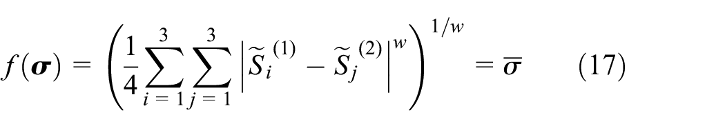
The

where
Since the full-field CP model can provide a larger number of yield stress points and plastic potentials data in 3D stress space, the Yld2004-3D yield function associated with AFR is difficult to accurately calibrate these materials sampling points simultaneously. Nevertheless, this limitation can be solved by the non-AFR in which the Yld2004-3D function is separately used as yield and plastic potential functions.
Non-associated flow rule framework
In classical plasticity theory, the AFR (please see Figure 3(a)) is employed to determine the flow direction of plastic strain increment
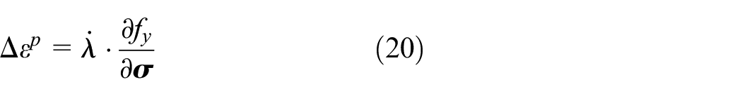
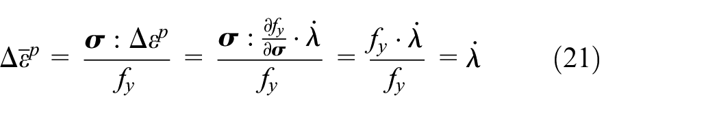
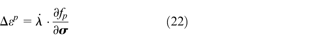
Therefore, the yielding and plastic potential are determined by the same yield surface. However, for strongly textured aluminium alloy, using the same yield surface is difficult to simultaneously calibrate the directional yield stresses and r-values.10,13,20 Alternatively, these issues have been successfully resolved using non-AFR in which the flow stresses and plastic flow directions were separately determined by yield function and plastic potential function. In non-AFR (please see Figure 3(b)), the plastic strain increments are determined by the first differential of the plastic potential function


The schematics of stress integration return mapping for bringing back elastic predictor on objective yield surface following: (a) AFR framework (return mapping normal to yield surface) and (b) non-AFR framework (return mapping normal to plastic potential surface).
In addition, the selection of combination of yield and plastic potential functions under non-AFR determines the accuracy of plastic constitutive model. There were various combinations have been developed including quadratic Hill series functions 37 and non-quadratic convex functions.10,38
The next increment corrects error (NICE) explicit integration scheme
The proposed anisotropic yield and plastic potential functions associated with non-AFR can be implemented in the commercial FE software Abaqus/Explicit via a user-defined material subroutine (VUMAT). Generally, a computationally efficient classical forward-Euler (CFE) scheme is applied as the standard explicit integration method. However, the satisfaction of consistency condition,

The application of NICE has shown that (i) compared with CFE scheme, the relative errors of the final stress, plastic strain and porosity are significantly reduced; (ii) when small strain increment is adopted to achieve the fulfilment of consistency condition, the significant reduction of the CPU time consumption is achieved against CBE scheme. Therefore, the NICE technique is employed in the elastoplastic constitutive model associated with non-AFR via VUMAT subroutine.
At the beginning of each time increment in VUMAT, the total strain increment
while the fully elastic predictor stress
where

when yield criteria

where the corrected


Here, the plastic tensor increment

when the plane stress assumption is accepted, the strain increment in thickness direction

where the variables
Additionally, to clarify the effectiveness of non-AFR in prediction of plasticity, the AFR based NICE explicit stress integration also has been developed by replacing the equations (22) and (23) with equations (20) and (21).
The hierarchical framework of the multi-level model
The CPFEM constitutive model was implemented into the general commercial FE solvers, ABAQUS/Standard. The anisotropic properties of textured aluminium alloy were explored by the virtual material test by loading the RVE in many deformation modes, for example, uniaxial tension, plane-strain tension, equibiaxial tension and pure shear. After each simulation, post-processing was implemented to read the stress tensor and strain rate for each loading case at the desired level of plastic work and respectively used as yield stress and plastic potential points for identification of yield functions. To find the optimal parameters of the selected yield functions, a fitting procedure was employed using the Levenberg-Marquardt nonlinear least square method (NLSM) in which the number of yield stress and plastic potential points is equal to or greater than the number of parameters. It was solved by minimising the residual value of

where
Materials of multi-level model
Material characterisation
Here, the full-filed CPFEM was applied to investigate the texture induced anisotropic plasticity of strong textured AA3104 aluminium alloy sheet (an Al-alloy with about 1% manganese and 1% magnesium40,41). This sheet was a typical canbody stock and was widely used in metal bodymaker industry due to its good formability and strength. To meet the strength (≥275 MPa) and low gauge (≤0.4 mm) requirements of aluminium can, canbody stock AA3104 is fabricated through a thermo-mechanical rolling process route from the direct chill, casting, homogenised, ingot that is hot rolled to 2.0 mm with a heavily strain hardened, hard rolled H19 temper (87–89% cold rolling reduction) to final gauge about 0.27–0.40 mm. Therefore, a pronounced rolling texture is acquired during thermo-mechanical processing, where the preferred crystallographic orientations are assembled along the so-called
To measure the crystallographic texture, a specimen with dimensions of 5 mm × 3 mm × 0.4 mm was prepared for crystallographic texture and orientation analyses using a FEI Quanta 3D field emission gun scanning electron microscope (FEG-SEM) equipped with an EDAX-TSL Hikari EBSD system. During the measurement, the EBSD mapping area was assigned to be 1 × 1 mm with a step size of 1 µm. The sliced orientation density maps were obtained from ODFs through the reduced Euler space
18.51%
22.51%
4.91%
11.26%
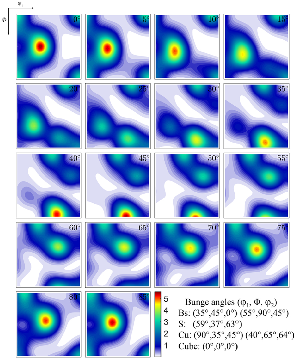
The orientation density map of 500 reconstructed grains from the orientation density function (ODF) of cold-rolled AA3104-H19 aluminium sheet as sections through the reduced Euler space for cubic–orthorhombic symmetry (constant
Therefore, the volume fractions 45.93% of cold rolled texture, in which the crystal orientation density is high along the
Here, a total of 500 crystallographic orientations generated by ODFs were randomly assigned into these grain cells of the RVE. To obtain a high resolution for each grain cell, the RVE discretised with 2,032,594 tetrahedron elements with about 4065 elements per grain in average and was shown in Figure 5.

A RVE generated by periodical Voronoi tessellation of 500 randomly placed seeds at resolution of 4065 tetrahedron elements each cell and each Voronoi cell (shown in various colour) represents one grain orientation for AA3104-H19 with a total of 500 crystallographic orientations generated by ODFs.
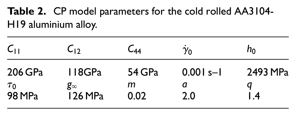
Material constants of CPFEM
The constitutive material constants of CPFEM were fitted through adjusting the predicted stress-strain curve to the experimental tests by applied three periodical boundary conditions on the surfaces of RVE, for example, uniaxial, plane-strain tension and pure shear in RD. Such experimental tests were performed on the well-designed AA3104-H19 specimens cut from the same sheet, that is, uniaxial tensile experiments were conducted following the ASTM-E8-E8M13 standard 43 and the specimen was tested using an Instron 1342 servo-hydraulic test system at the loading speed of 0.005 mm/s. Artificial speckle patterns were sprayed on the specimen surfaces and the loading processes were recorded for strain measurement using digital image correlation (DIC) method (please see Figure 6(a)). The CCD camera frame rate was configured at 20fps, hence, the uniaxial stress versus Misses equivalent strain curve was measured. The results show the uniaxial yield stress of AA3104-H19 in RD is about 262 MPa. The calculation of uniaxial r-value using the plastic incompressibility condition is given by:
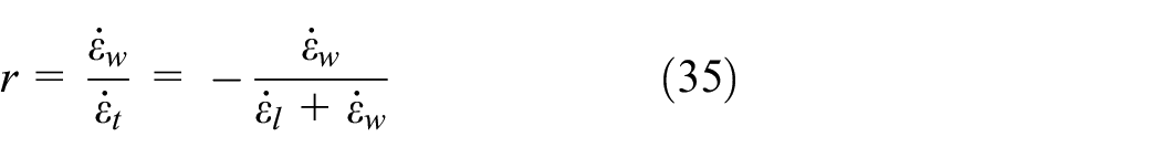
where

where,

Mises equivalent strains measured by DIC method for: (a) uniaxial tensile experiment, (b) plane-strain tensile experiment, (c) pure shear experiment, the distribution of Mises equivalent stresses of RVE predicted by CPFEM applied with various boundary conditions for, (d) virtual uniaxial tension, (e) virtual plane-strain tension and (f) virtual pure shear.

Comparison of stress–strain curves for uniaxial tension, plane-strain tension and pure shear obtained by experimental tensile tests (solid lines with various colours) and predicted by virtual CPFEM tests (dot lines with various colours).
CP model parameters for the cold rolled AA3104-H19 aluminium alloy.
Forming experiment and simulation
To operate the standard cup drawing experiments of round blank, a tooling system with punch, drawing die and blank holder was designed and manufactured (please see Figure 8(a)). The configuration and dimensions of the experimental setup are summarised in Figure 8(c). The round blanks with a radius 30 mm was cut from a 0.4 mm AA3104-H19 sheet using electro-discharge machining, and then they were deep drawn using a single stroke with a speed of 0.1 mm/s. The blank holder force about 5.0 kN and lucubration were employed to avoid flange wrinkling and surface scratching, respectively.
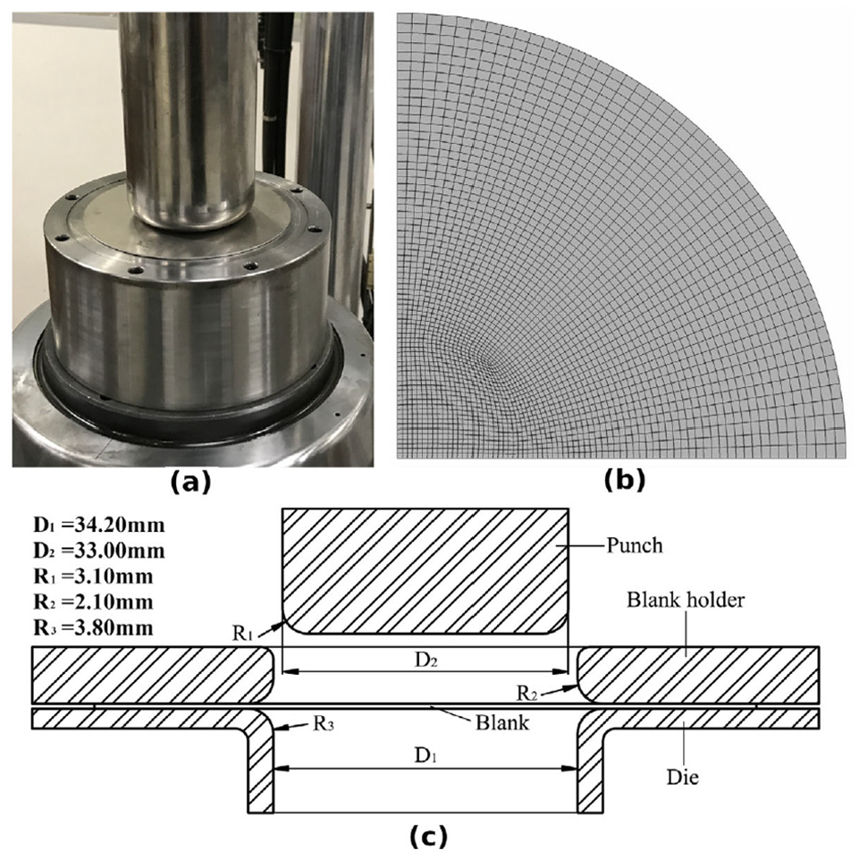
The schematics of forming experiment and simulation for: (a) deep drawing tooling system with a punch, a drawing die and a blank, (b) mesh quality of initial blank discretised with 7839 elements each layer and (c) configuration and dimension of the tooling system.
To numerically evaluate the out-of-plane anisotropy as well as plasticity flow rule, the VUMAT subroutines of CPFEM determined plane stress Yld2000-2d and 3D Yld2004-18p yield functions associated with AFR and non-AFR were separately used to simulate deep drawing of an AA3103-H19 sheet. For the mesh of blank, 3D stress C3D8R and plane stress S4R element type were employed in Yld2000-2d and Yld2004-18p models, respectively (please see Figure 8(b)). Punch, blank holder and drawing die were constrained as rigid bodies. Friction conditions between the sheet metal and tooling system are important factors that affect the prediction of sheet metal forming simulation. The isotropic Coulomb friction model with a coefficient
Results
Validations
The experimental tensile tests in various directions were performed to validate the anisotropic properties predicted by the CPFEM. Here, the specimens used for uniaxial tension and shear tension were prepared from the same sheet at an angular interval of 15° from the RD. Plane strain specimens were prepared at an angular interval of 45° from the RD. For the CPFEM prediction, the anisotropic properties were determined by rotating the grain orientation. The r-value was calculated using the strain rates which are determined by the deformation rates of cubic RVE between
Figure 9(a) to (d) show a comparison of the anisotropic properties predicted by the virtual tests with those from mechanical experiments. It can be seen that the directional r-values and uniaxial stresses predicted by CPFEM coincided with those experimental results (please see Figure 9(a) and (b)). Additionally, the results showed r-value appear two major peaks near
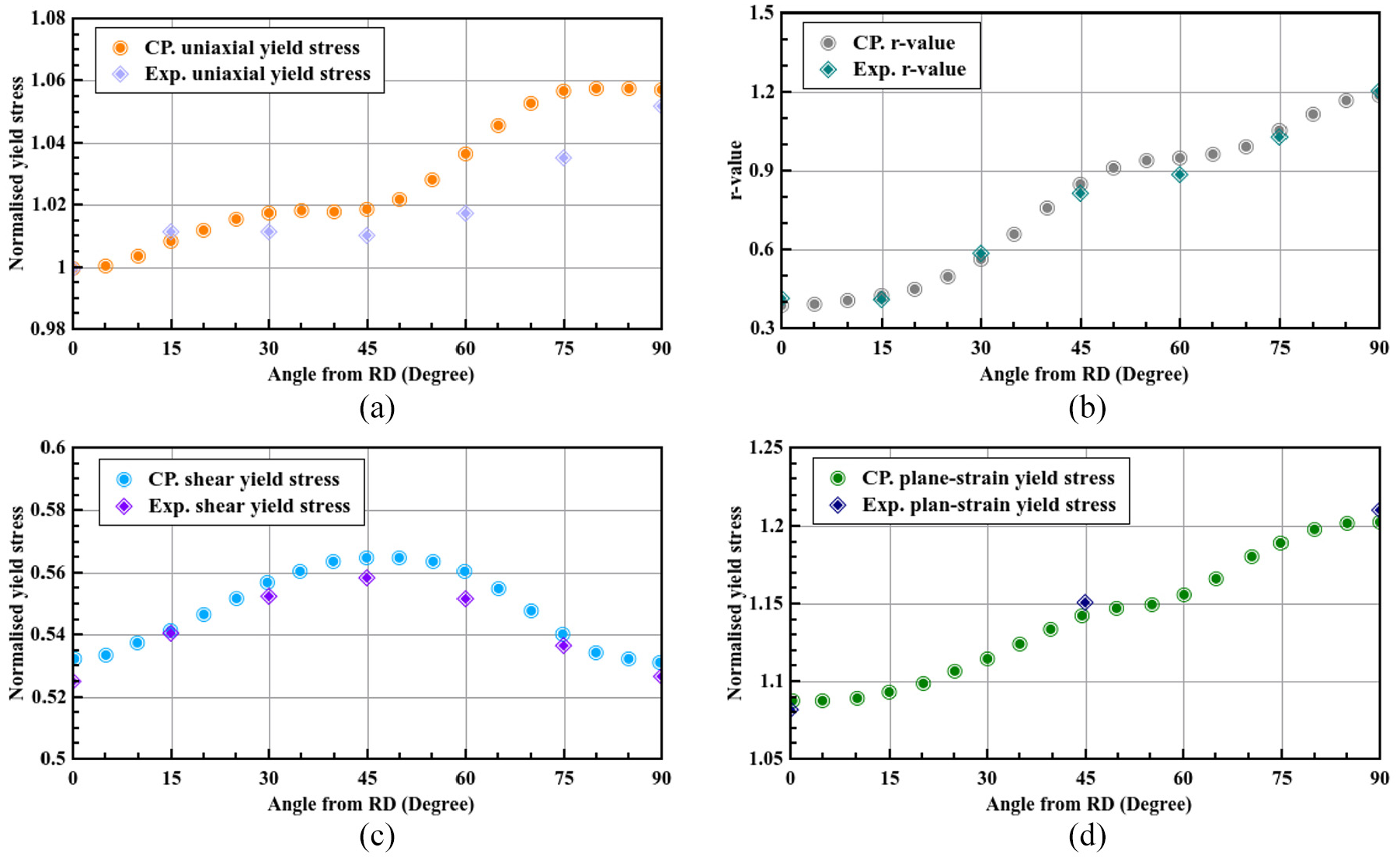
Comparisons of in-plane mechanical anisotropies obtained by experimental tensile tests and predicted by virtual CPFEM tests in various stress states for: (a) normalised uniaxial yield stress variation from RD to TD, (b) normalised uniaxial r-value variation from RD to TD, (c) normalised plane-strain yield stress variation from RD to TD and (d) normalised pure shear yield stress from RD to TD.
As a result, the predictions of the virtual tests operated by the full-field CPFEM showed good agreement with those experimental results. It indicates that the virtual material tests could be an alternative to the extensive and costly physical tests.
Calibration of yield and plastic potential functions
In this section, the mechanical anisotropies of the AA3104-H19 sheet were described using the advanced plan stress Yld2000-2d and 3D stress Yld2004-18p yield functions associated with both AFR and non-AFR. The calibrations of plan stress Yld2000-2d yield function were determined using the in-plane anisotropy in [RD-TD] plane predicted by the virtual tests. The calibrated parameters of Yld2000-2d are documented in Table 3. Additionally, not only the in-plane anisotropy in [RD-TD] plane but also the out-of-plane anisotropy in [RD-ND] and [TD-ND] planes were involved in the determination of parameters for 3D stress Yld2004-18p yield function. The calibrated parameters of Yld2004-18p are documented in Table 4. Here, the uniaxial yield stress at specific plastic work of 1 MPa and r-values between the plastic strain of 2%–10% were used to determine the parameters of yield functions.
The parameters of Yld2000-2d for AA3104-H19 aluminium alloy.

The parameters of Yld2004-18p for AA3104-H19 aluminium alloy.

Figure 10(a) and (b) show the yield functions calculated and CPFEM predicted uniaxial yield stresses and r-values in [RD-TD] plane, respectively. The CPFEM prediction showed that uniaxial stresses are slightly increasing from RD to TD and appear two peaks at around 30° and 75°, while r-values significantly increase from RD to TD and appear two peaks at about 50° and 90°. These results indicated that Yld2000-2d and Yld2004-18p associated with non-AFR successfully describe the variation of uniaxial stresses and r-values of AA3104-H19. In contrary, the deviation of fitting using AFR was significantly greater than non-AFR for both the Yld2000-2d and Yld2004-18p yield functions.
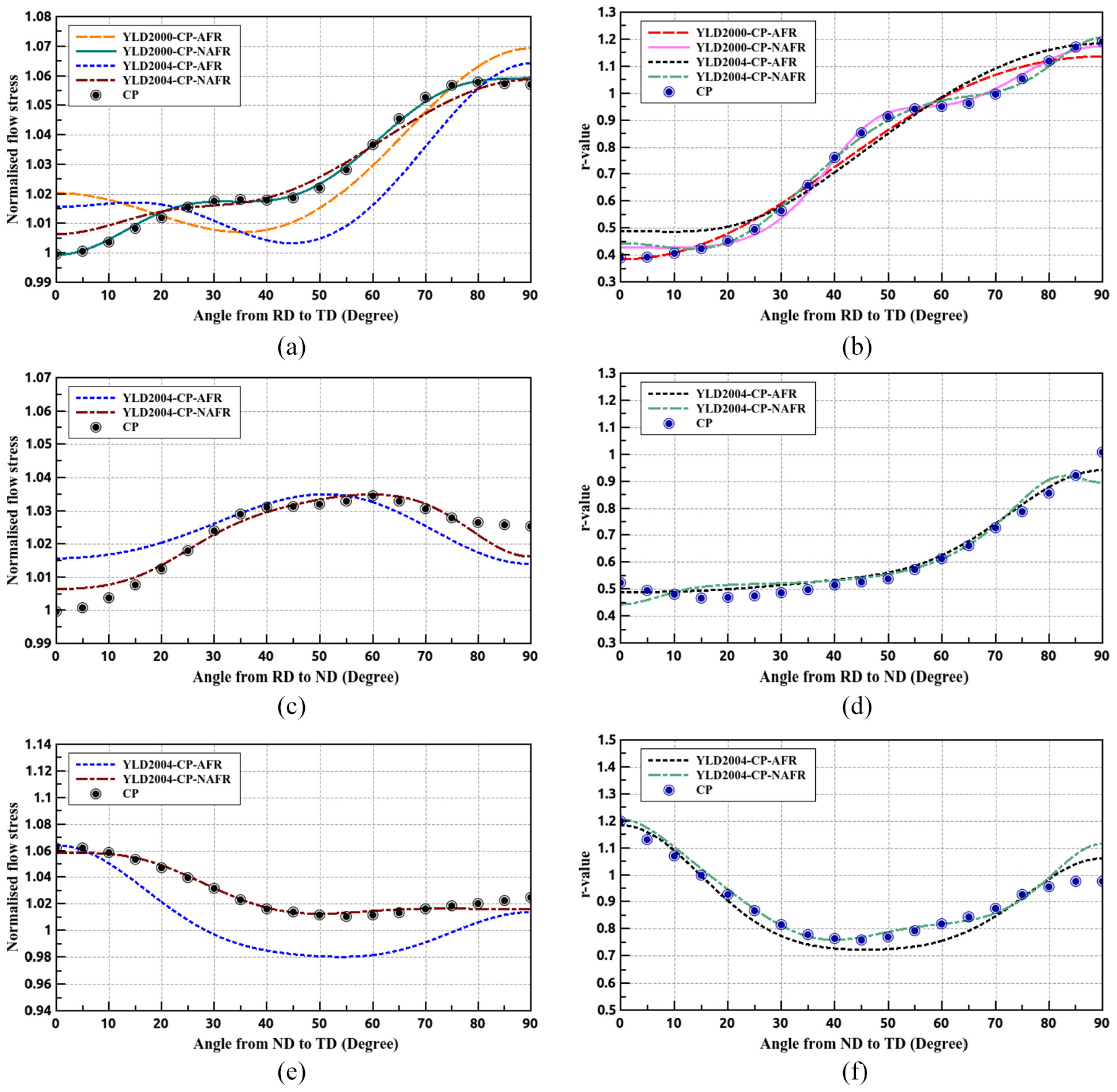
Comparisons of in-plane and out-of-plane mechanical anisotropies predicted by virtual CPFEM tests and calculated by various yield functions for: (a) normalised uniaxial yield stresses variation in [RD-TD] plane, (b) uniaxial r-values variation in [RD-TD] plane, (c) normalised uniaxial yield stresses variation in [RD-ND] plane, (d) uniaxial r-values variation in [RD-ND] plane, (e) normalised uniaxial yield stresses variation in [ND-TD] plane and (f) uniaxial r-values variation in [ND-TD] plane.
In addition, although the accuracy of calibration using Yld2000-2d associated with non-AFR was superior to other functions in [RD-TD] planes, Yld2000-2d cannot describe the out-of-plane anisotropy. Therefore, only Yld2004-18p associated with AFR and non-AFR were used to calibrate the CPFEM predicted uniaxial yield stresses and r-values in both [RD-ND] and [TD-ND] planes, as shown in Figure 10(c) to (f). Figure 10(c) and (d) show that CPFEM predicted directional uniaxial yield stresses in [RD-ND] plane are slightly stronger at 60° and weakest at 0°, while the predicted r-values are almost constant from 0° to 50° and then significantly increase to about 1.0 in ND. For the mechanical anisotropy in [TD-ND] plane (please see Figure 10(e) and (f)), the predicted normalised uniaxial yield stress decreased from 1.061 in TD to 1.011 at 55° and then slightly increased to 1.022 in ND. Moreover, the predicted r-value is lowest at 45° and greatest in TD. The comparison of out-of-plane mechanical anisotropy between prediction of the CPFEM and the phenomenological yield functions indicated that the accuracy of fitting for out-of-plane anisotropy using Yld2004-18p yield function associated with non-AFR is superior to AFR. Figure 11(a) and (b) show the distribution of directional uniaxial yield stresses in 3D polar coordinates generated by Yld2004-18p yield functions associated with AFR and non-AFR, respectively. It can be seen that yield function associated with non-AFR provided greater flexibility to accurately capture the variation of uniaxial yield stresses aligned various 3D spatial directions (please see Figure 10(a), (c) and (e)). Essentially, it is due to non-AFR enable the yield function only account for yield stress, unlike the AFR in which the yield surface is simultaneously determined by the yield stresses and plastic potentials.

The variation of uniaxial yield stresses of various materials orientations in 3D polar coordinates generated by: (a) Yld2004-18p associated with AFR and (b) Yld2004-18p associated with non-AFR.
For the mechanical anisotropy in multi-axial stress states, the yield surfaces generated by considering all phenomenological yield functions using yield stress points provided by the virtual multi-axial tensions in [RD-TD], [RD-ND] and [TD-ND], respectively. Figure 12(a) shows a comparison between the predicted yield surfaces and the 2D yield stress points in [RD-TD] plane generated by the virtual tests at a plastic work per unit volume of 1 MPa. It can be seen that Yld2004-18p yield functions associated with both AFR and non-AFR can accurately fit the 61 yield stress points provided by virtual tests in [RD-TD] plane. However, the Yld2000-2d associated with both AFR and non-AFR showed a minor difference to the CPFEM predictions being a little more ovality in the region around equibiaxial stress state. This is because the Yld2000-2d yield function is less flexible than the Yld2004-18p due to its smaller number of fitting parameters. As illustrated in Figure 12(b) and (c), 62 and 60 biaxial yield stress points in [RD-ND] and [TD]-[ND], respectively, were applied to generate various yield surfaces using the Yld2004-18p yield function associated with AFR or non-AFR. It can be seen that there is a good agreement between the yield stress points and yield surfaces determined by the Yld2004-18p yield function associated with both AFR or non-AFR.

Comparison of yield stress points predicted by virtual CPFEM tests and yield surface calculated by various yield functions for various loading rates of biaxial stress states for: (a) normalised
Figure 13(a) to (d) show the 3D yield surfaces in the stress space of [

The multi-axial yield surface contour maps associated with various shear stress levels plotted in the three dimensional stress space [
Earing profile predictions
This subsection presents the results of AA3104-H19 cup drawing simulations using both yield functions Yld2000-2d and Yld2004-18p which are implemented in the AFR and non-AFR based NICE scheme linked to the ABAQUS/Explicit via the user material subroutines VUMAT. Figure 14(a) shows the predicted earing profiles of all considered models in cylindrical cup-drawing and those results were compared with the experimentally determined cup earing profiles. All experimental cup earing profiles exhibit six major ears located at

The results of deep drawing simulations for AA3104-H19: (a) comparison of earing profile achieved by experimental deep drawing tests and predicted by FE simulations using various virtual CPFEM tests determined yield functions and (b) the RMSD of the earing profile predicted by various yield function using the number of cup height data from 0° to 360° at an interval of 1° in comparison with experimental results.
In order to quantify the accuracy of predictions, the RMSD of cup height is calculated using following equation,
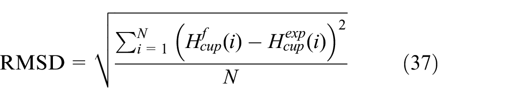
where

The configurations and equivalent plastic strain distribution of the deep drawn cups predicted by FE simulations using various virtual CPFEM tests determined yield functions: (a) Yld2000-2d associated with AFR, (b) Yld2000-2d associated with NAFR, (c) Yld2004-18p associated with AFR and (d) Yld2004-18p associated with NAFR.
Discussions
The multi-level model with hierarchical structure was used to study the crystallographic texture induced anisotropy and its effects on plastic deformation of AA3104-H19. The validation of full-field CPFEM predictions was presented and the results showed good agreement with experimental results with respect to various deformation modes for the AA3104-H19 sheet. It is interesting to compare the fitting deviation using different plastic flow rules for both Yld2000-2d and Yld2004-18p. The results obtained with the calibrated Yld2004-18p and Yld2000-2d associated with non-AFR indicated that both yield functions were capable of describing the in-plane plastic anisotropy determined by the underlying CPFEM with good accuracy. Simultaneously, CPFEM predicted the out-of-plane can be captured by Yld2004-18p using non-AFR well. For the AFR based model, neither Yld2000-2d nor Yld2004-18p can capture the sampling points of materials in 2D or 3D stress space. All considered yield functions reproduced the curvature and radius of the yield surface closely to what was determined by the CPFEM models.
It was interesting to note that the influence of out-of-plane anisotropy on plastic deformation is not negligible in sheet metal forming simulations. In other words, the comparison of earing profile prediction using Yld2000-2d (only consider in-plane anisotropy) and Yld2004-18p (consider with in-plane and out-of-plane anisotropy) in Figure 14(a) indicated that the accuracy of plastic deformation prediction is improved when the employed yield function involved with the out-of-plane anisotropy. This was because the black holder compression force is applied on the flange region of the sheet metal in the thickness direction and an out-of-plane force happens in the bending region during the deep drawing process.
Additionally, it was quite clear that the accuracy of both Yld2004-18p and Yld2000-2d associated with non-AFR is better than that of AFR. Therefore, from the results one may conclude that when the non-AFR Yld2004-18p yield function is employed the accuracy of this hierarchical multi-scale model is mainly determined by the quality of the full-field CPFEM in reproducing the experimentally measured mechanical anisotropy. In other words, when a high-resolution crystallographic texture is available for the CPFEM, the Yld2004-18p associated with non-AFR seems capable of giving a realistic description of the texture induced plastic anisotropy in 3D stress space.
Since the CP determined Yld2004-18p yield function associated with non-AFR is superior in the prediction of plastic deformation during the sheet metal forming process, this constitutive model could be readily applied to perform some design oriented parametric studies in the future investigation, for example, tooling system optimisation, initial blank shape design and texture controlling for sheet metal rolling processes.
Conclusions
This work proposed a hierarchical framework of the multi-level model, that is, a multi-scale scheme, in which phenomenological yield function and full-field CPFEM are employed at the continuum scale and mesoscale, respectively. In this method, advanced phenomenological yield functions were successfully implemented in FE models and can be used to operate the accurate metal forming simulations at the engineering scale with relatively low computational costs, while the CPFEM provided yield stress and plastic potential points to determine the parameters of advanced yield functions.
Here, the mechanical anisotropy of an AA3104-H19 aluminium alloy sheet has been studied by the experiments, full-field CPFEM as well as various phenomenological yield function in 2D and 3D stress space. The full-field CPFEM predictions exhibited a good capability in reproducing experimentally observed mechanical anisotropy of AA3104-H19. Additionally, it is noted that the prediction of 3D Yld2004-18p yield function associated with non-AFR show a good agreement with the CPFEM predicted mechanical anisotropy and experimentally measured cup earing profiles.
Since the multi-level model bridged the CP model and the phenomenological anisotropic plasticity, it would be helpful to quantify the microstructure effects of polycrystal orientations on the texture induced mechanical anisotropy of as-rolled sheet metal. In addition, the CPFEM and anisotropic elasto-plastic constitutive models were presented in a general form so that they can be readily employed for other aluminium alloys in sheet forming applications as well as texture controlling for sheet metal rolling processes.
Footnotes
Handling Editor: James Baldwin
Declaration of conflicting interests
The author(s) declared no potential conflicts of interest with respect to the research, authorship, and/or publication of this article.
Funding
The author(s) disclosed receipt of the following financial support for the research, authorship, and/or publication of this article: This paper is funded by National Natural Science Foundation of China [Grant Number: 12002211].