
Abstract
S-shaped test piece is used to assess the performance of five-axis numerical control machine tools. Compared to traditional test method and test pieces, it performs better and was agreed to be included in the draft international standard at the 79th ISO/TC39SC2 meeting. However, the lack of theoretical research is the barrier to apply for standard and to be widely used. Therefore, this paper aims to study one of the theoretical research that how to choose the suitable tool diameter. We proposed a new research method based on software AdvantEdge, Vector Method for error calculation, Microelement Model of cutting force and deformation model of cantilever beam. The simulation results show that the 20 ≤ diameter < 30 is the proper choices and the 20 is the best choice, which is consistent with the empirical consequence. This method not only provides the theoretical support for the S-shaped test piece, but also can be applied to other parts with complex curved surfaces.
Keywords
Introduction
S-shaped test piece,1,2 proposed by Chengdu Aircraft Industry Group, is a standard test piece and can be used for comprehensive testing of five axis machine tools. This standard specimen aims at solving the problem that machining parts with complex surfaces (such as the aerospace thin-walled components) may be unqualified when the machine tool has passed the traditional test method. Five-axis machine tool is different from three-axis one, so the previous detection methods (e.g. R-test 3 ) or test pieces (e.g. NAS specimen 4 ) cannot reflect the processing performance of five-axis machine accurately. Even though in these methods or sample testing qualified basis, Out-of-roundness-tolerance parts will still exist when processing. Through the newly proposed S-shaped test piece, the performance of the qualified machine tools can meet the processing requirements. Therefore, this test piece was included in the draft standard (DIS) at the 79th ISO/TC39SC2 meeting in May 2016. 5
However, the shortcoming of S-shaped test piece is that it was proposed based on practical experience. Therefore, despite of repeated modification and research, its theoretical support is still lacking, which is a serious problem to apply for international standards.6,7 In addition, due to the lack of theoretical support, S-shaped test piece cannot find where the issues exist if unqualified, as the previous methods do. Therefore, the theoretical research on S-shaped test piece and the study of error tracing based on the theoretical research are the necessary ways to improve and popularize the S-shaped test piece.
One of the theory research is the selection of the tool diameter when machining S-shaped test piece. Chengdu Aircraft Industry Group have found the 20 mm of diameter is most appropriate for machining S-shaped test piece, which cause deformation error and the theoretical error in the optimum state. However, the company failed to give the theoretical explanation of this choice. This paper studies on this problem. The importance of this issue is that the S-shaped test piece is proposed to test the performance of the machine tool. Because the deformation error and the theoretical error caused by unreasonable tool diameter cannot reflect the performance of the machine, so they must be optimized as much as possible.
However, because of the mass production, the engineering experience and multiple processing early trials are enough to choose suitable tool diameter. Therefore, the related theoretical research is little. This paper puts forward the research method of the selection of the optimal tool diameter when machining S-shaped test piece. During the pre-treatment, we use the Vector Method for error calculation 7 in order to simplify the calculation. Then, the milling simulation software AdvantEdge 8 is used to obtain the cutting parameters. Next, the cutting force is calculated according to the Microelement Model. 9 Finally, discrete points of tool axis can be obtained according to the Deflection Formula and the total error can be calculated. The simulation results show that the ideal tool diameter range is 20–30 mm, and the optimal tool diameter is 20 mm. This study not only provides theoretical support for cutting tools with diameter of 20 mm when cutting S-shaped test piece, but also can provide theoretical reference to the selection of the tool diameter when machining any parts with complex surface, which has important significance in theory and practice.
Theoretical error and deformation error
Figure 1 shows the model of the S-shaped test piece, which is consist of two S surfaces A and B, and the surfaces are composed of two S type B spline curves, top curve C1(u) and bottom curve C2(u). 6

S-shaped test piece. 6
The projection of top curve C1(u) and bottom curve C2(u) is not consistent, so the existence of twist angle γ7 cause the theoretical error of the S-shaped test piece, as shown in Figure 2. Because the theoretical error cannot been eliminated due to twist angle, the researchers have proposed all kinds of method to position tool.6,10–12 This paper adopt the traditional Single Point Offset (SPO) 10 method with top curve to conduct the simulation, as it is the most popular method.

Twist angle. 7
When the method to position the tool is the same, the smaller tool diameter would lead to little theoretical error. In the extreme case where tool diameter equals zero, the theoretical error would disappear. However, the smaller the tool diameter is, the worse the stiffness of tool is. Therefore, the tool is more prone to large deformation in the machining process. Since the deformation error decreases with the decrease of tool diameter and the theoretical error decreases with the increasing of tool diameter, the selection of tool diameter is crucial. The processing performance should not contain the theoretical error and deformation error, so giving the appropriate recommendation value of tool diameter is necessary.
Optimization of tool diameter based on simulation
Optimization process
The block diagram of the principle of simulation in this paper is shown in Figure 3. Firstly, according to the calculation principle of SPO, we compile MATLAB program to generate G code files, and import G code data to milling processing simulation software AdvantEdge According to the calculation principle of SPO, we compile MATLAB program to generate G code files, import G code data to milling processing simulation software AdvantEdge, and simulate milling of S-shaped test piece. The AdvantEdge can give the corresponding cutting parameters for each row G code. Secondly, the cutting parameter is introduced into the Microelement Model to calculate the cutting force. Then the flexural cantilever model and the Deflection Formula obtain the deformation value and deformation direction of each point on the tool axis. Finally, the actual coordinate of discrete points of the tool axis can be calculated, so the minimum distance between the discrete points and test points is considered as the error value, which includes theoretical error and deformation error.

The block diagram of simulation calculation.
However, for the sake of accuracy, the G code data imported to the AdvantEdge need to be especially dense, which makes G code data lengthy (up to hundreds of thousands of lines). In addition, when the discrete points are finally obtained, the data becomes larger and larger and makes the calculation slow. Therefore, using the Vector Method for error calculation and finding the main G code data would decrease the data size. In this process, the objective tool axis appears the minimum distance to the test point is considered. Then, one G code corresponds to one tool axis, so extract G code data near the objective G code can decrease data size a lot. For example, assuming that there are 30 test points and we consider ±10 lines away from the objective G code, only 6300 lines of G code will be used for subsequent calculation. Compared to the hundreds of thousands of lines at the beginning, the optimized method (shown in Figure 4) significantly decrease the computing time.

Optimized block diagram of simulation calculation.
The Vector Method for error calculation
The Vector Method is shown in Figure 5. The test point M is the point on the ruled surface. O is the point of tool tip.

The vector method.
The Microelement Model
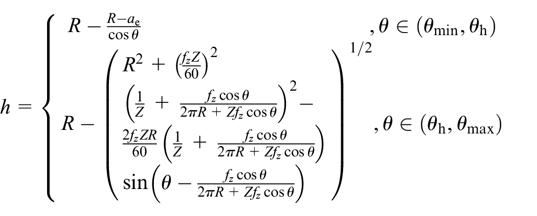
Figure 6 shows the milling force of Microelement Model. In the process of cutting the workpiece, the corresponding cutting center angle range is [θmin, θmax]. The range is divided into N equal proportion θ1, θ2,…,θn-1, θn, where θi represents a range of dθ (For example, θ1 represent [θmin, θmin + dθ], and so on). This method is equivalent to discrete a spiral-milling cutter to many tiny discs along the tool axis at equal intervals dz (With the spiral angle β and the tool radius R, we obtain dl = tanβ·dz = R·dθ, so dz = R·dθ/tanβ). Every tiny disc can be seen as a thin spiral-milling cutter with axial width dz, so according to the empirical formula, it can be obtained:

where

Milling force of microelement model.
In the above parameters, dz depends on dθ, which can be given as needed. However, θmin, θmax and

A schematic diagram of cutting center angle θ.
The expression of calculation of instantaneous cutting thickness is as follows 9 :
Deformation computation
The schematic diagram of cutting force of a microelement is shown in Figure 8. Assuming that the cutting center angle of the tiny disc of the tool is θi, the tangential force

The schematic diagram of the cutting force of a microelement.
The actual deformation is particular complex and there are still many deformation directions under the Microelement Model. It is necessary to ignore secondary factors in order to simplify the calculation and analysis, so only the deflection deformation along the direction of vector
As shown in Figure 9, the point O is the fixed point and the point K is the loading point. Therefore, the deflection

where F is the applied load, the E is the elastic modulus of the equivalent cantilever beam, and the I is the polar moment of inertia of the equivalent cantilever beam. According to the principle of superposition method to calculate the deflection, the sum of the deflection of the tiny disk under each

The diagram of deflection calculation.
Therefore, according to the Microelement Model in Section 3.3, the process diagram to calculate the actual coordinates of the discrete points of tool axis after the deformation is shown in Figure 10. Firstly, for each discrete point

The process diagram to calculate the actual coordinates of the discrete points of tool axis after the deformation.
Simulation results
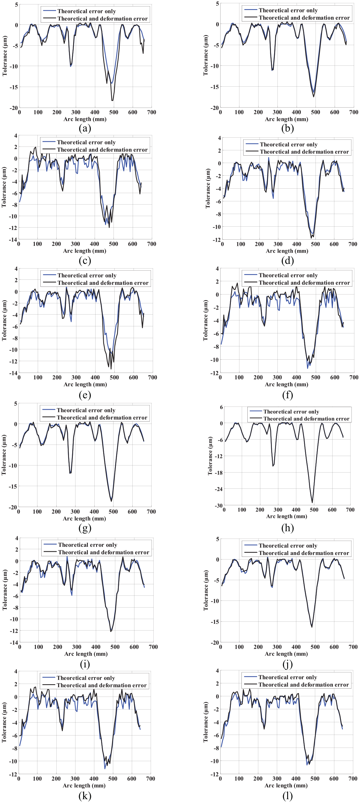
The simulation results are shown in Figure 11 with the d = 18, 20, 22, and 30. The selection of tool diameter sequence is referenced by the recommended value of GBT 6117.1-1996. 15 The following conclusions can be drawn from the simulation results:
From the numerical point of view, the deformation error may make up for the theoretical error or have the same sign, so the total error may decrease or increase, which is consistent with the theory research before.
When d < 20 mm, the influences of deformation error become apparent where the maximum deformation error gradually close to 5 μm, as shown in Figure 12. It is mainly caused by two reasons: one is that the theoretical error is reduced with the decrease of tool diameter; the other is that the deformation error increase. If the tool diameter continuously decrease to a smaller d, the tool deformation error can even reach dozens of microns, far in excess of the theoretical error. However, when d ≥ 20 mm, the deformation error is smaller relative to the theoretical error. In addition, the basic trend superposition is unchanged after the superposition of the deformation error. If the tool diameter continuously increases to d = 30 mm, the theoretical error will increase gradually due to the twist angle of S surface and excess 10 μm than d = 20 mm. In a word, the ideal tool diameter is more than or equal to 20 mm and less than 30 mm, and the total error is smallest at the best choice d = 20 mm, which is consistent with the experiment conclusion the Chengdu Aircraft Industry Group has made.
The positive correlation between the deformation error and the height of H is contrary to the theory of cantilever beam that the deformation error is larger with smaller H. However, it actually does not violate the theory. Firstly, the positive correlation only occurs when the tool diameter is larger. For example, it shows the negative correlation when d = 18 mm. Secondly, why the relativity changes as the diameter? It is because that the calculation of discrete points of actual tool axis need two parameters: one is a vector to show the direction of deformation; the other is a scalar to define the deformation degree. If tool diameter is small and deformation error is large, the scalar is the major factor and the relationship is consistent with the cantilever beam hypothesis. However, when tool diameter is large and deformation error is small, the vector play the leading role. It is why the scalar only reach to 1 μm but deformation error up to 2–3 μm when d = 20 mm. This paper adopt the SPO method with top curve to position tool, so the top curve appears the least theoretical error near zero and the bottom curve shows the most one. As demonstrated in Figure 13, the point O and the ellipse around O represent the position of the tool tip, and the point O has zero theoretical error. Any point E at the ellipse around O will cause theoretical error. As the position method is SPO based on top curve, the tool is located at the O point for the top curve and the E point for the bottom curve. At this time, the deformation cause O and E shift away from the initial position. For the O point, every direction of deformation will make the error become larger and more obvious. However, for the E point, many direction of deformation will lead to minor changes or even make the error smaller. In addition, there will be no changes if it still locates at the circle whose center is the point O and radius is ||OE||. Therefore, the positive correlation appears between the height of H and the deformation error when the direction of deformation dominates.

The simulation results of theoretical error and deformation error: (a) d = 18 mm and H = 7 mm, (b) d = 20 mm and H = 7 mm, (c) d = 18 mm and H = 15 mm, (d) d = 20 mm and H = 15 mm, (e) d = 18 mm and H = 23 mm, (f) d = 20 mm and H = 23 mm, (g) d = 22 mm and H = 7 mm, (h) d = 30 mm and H = 7 mm, (i) d = 22 mm and H = 15 mm, (j) d = 30 mm and H = 15 mm, (k) d = 22 mm and H = 23 mm, and (l) d = 30 mm and H = 23 mm.
The deformation error when d = 18 and d = 20.

The explanation for the less deformation error.
Conclusion
The proposed S-shaped test piece is of great significance for the accuracy inspection and performance evaluation of five axis machine tools. However, the theoretical support is rather deficient, which limits the popularization and application of the S-shaped test piece. This paper analyzes the reason of the theoretical error and deformation error, and explains the trend of the error changes with tool diameter changes. The core is to put forward the reasonable selection method of tool diameter. This method combines the Vector Method, the Microelement Model and the Deflection Formula. The whole calculation process is clear, simple and direct, and finally give the appropriate selection of the tool diameter when machining S-shaped test piece, which is consistent with the company’s experimental result. This method can not only be applied to the selection of tool diameter for S-shaped test piece, but also provide theoretical reference for the selection of tool diameter when machining arbitrary parts with complex surfaces.
Footnotes
Handling Editor: James Baldwin
Declaration of conflicting interests
The author(s) declared no potential conflicts of interest with respect to the research, authorship, and/or publication of this article.
Funding
The author(s) disclosed receipt of the following financial support for the research, authorship, and/or publication of this article: This research was financially supported by The National Natural Science Foundation of China (Grant No. 51675301).