
Abstract
Imbalance vibration is the main factor affecting the stability of rotating machineries equipped with active magnetic bearings (AMB). Accordingly, for safe and reliable operation, ISO 14839 standard sets out guidelines for measuring and evaluating the vibration and stability. However, technical approaches to realize fulfillment of the evaluation criteria have never been studied in theory. This paper presents insights of these criteria and proposes effective methods to simultaneously implement these evaluation criteria. Based on imbalance vibration model of AMB-rotor system, the theoretical connections between these evaluation indices are revealed. In order to obtain accurate vibration model of single-input single-output (SISO) AMB-rotor system, modal analysis is carried out and equivalent mass of SISO system is figured out. Afterwards, with the analysis of sensitivity function in theory, new indices of the evaluation criteria are proposed, which helps establish requirements of controller design and rotor balance quality. Finally, through experimental verification on a test rig, the limitations on the evaluation criteria can be negligible, and the proposed methods to simultaneously implement the evaluation criteria are validated.
Introduction
Since for no contact between bearing and rotor, active magnetic bearings (AMB) permit rotating operation of machineries with no mechanical wear and no lubrication. Consequently, it brings about many advantages such as high speed, high power density, less maintenance, and lower cost. 1 AMB have become alternatives to high-performance bearings in many applications, ranging from industrial centrifugal compressor, 2 high-speed centrifugation, 3 flywheel energy storage system, 4 to astronautic three-axis inertially stabilized platform, 5 suspended gyro. 6
Similar to any other rotating machines, machineries equipped with AMB own imbalance vibration problems as well. It can be caused by design, material, manufacturing and assembly. Accordingly, some standards concerning performance evaluation of AMB equipped machineries are prompted.7–10 Especially Part 2 and 3 of the standard focus on the vibration and stability evaluation of the system, which helps evolve an industry consensus on requirements of performance. However, the evaluation process is always carried out when the procedure of design, manufacture, assemble and commissioning is finished. There is no valid theoretical guidance during design and manufacturing process in order for implementation of these evaluation criteria.
As for ISO 14839-2 standard, the maximum value of shaft vibratory displacement is regarded as an index for vibration evaluation. 8 One of the influence factors of rotor vibration is the closed-loop control property, which is determined by AMB and controller design. The other one is the magnitude of rotor mass unbalance. It is well known that rotor balancing during manufacturing process is an effective procedure to adjust the distribution of rotor mass unbalance. Based on worldwide experience, balance quality grades have been established in ISO 21940-11 standard, 11 which permit a classification of the balance quality requirements for typical machinery types. However, different from most machineries supported by traditional mechanical bearings, AMB equipped machineries own much larger bearing clearance. Therefore, large vibratory motions of the operating rotor shaft should be permissible if there are no rubs between the rotor and bearings. In other words, the guidance for balance quality grades in ISO 21940-11 standard is not applicable for AMB equipped machineries. To the authors’ knowledge, there has been no theoretical analysis to provide appropriate guidelines of balance quality grade selection for AMB-rotor system.
In order to assess the stability with vibration, sensitivity function is adopted in ISO 14839-3 standard,
9
which is related with the closed-loop control system. With regard to AMB control algorithm, there are many research achievements in recent decades. Based on the most widely used algorithm, that PID control,12,13 many improvement methods are researched. The fuzzy logic-based intelligent control strategy is introduced.
14
Besides, the fractional-order PID control is designed to achieve more favorable dynamic performance.
15
In order to reduce rotor response and improve levitation accuracy, the derivative control action is proposed to be high-frequency band-limited.
16
What is more, many modern control techniques are designed for AMB as well, such as
For the above purposes, methods to simultaneously implement the evaluation criteria in ISO 14839-2 standard and ISO 14839-3 standard are deduced and presented in this paper. Firstly, in section 2, imbalance vibration of an AMB-rotor system is modeled, with which the theoretical connections of the evaluation criteria are obtained. In section 3, in order to acquire an accurate vibration model, finite element method is carried out to analyze the modal of a test model, and the equivalent mass of the single-input single-output (SISO) AMB-rotor system is derived. In section 4, with the analysis of sensitivity function, two new indices of the evaluation criteria are proposed. Accordingly, the requirements of controller design and balance quality grade are established in theory. Subsequently, the proposed methods are verified through experiments in section 5. At last, section 6 concludes this paper.
Insights of the evaluation criteria
First of all, based on the mathematical model of imbalance vibration, deep insights of the evaluation criteria of ISO 14839-2 standard and ISO 14839-3 standard are provided. The connections between these criteria and their limitations are analyzed.
Imbalance vibration model
It is known that AMB are inherently unstable due to a negative stiffness, and a feedback control is required to make AMB operate in a stable equilibrium. However, vibration derived from mass unbalance still exist, which is the main evaluation objective of ISO 14839 standard. Therefore, vibration of AMB-rotor is modeled and analyzed. The definition of variables is seen in Appendix 1.
The block diagram of an AMB-rotor system can be depicted as Figure 1.

Block diagram of an AMB-rotor system.
With a positive stiffness (k) and a damping component (d), the differential equation of motion can be expressed as


The main disturbance force in radial direction is derived from mass unbalance. So

where

Thus, the relations between amplitude of vibration response and rotational speed are obtained. And we can get some conclusions as follows:
When the rotational speed is big enough, the amplitude of vibration response approaches eccentric distance:

If

If
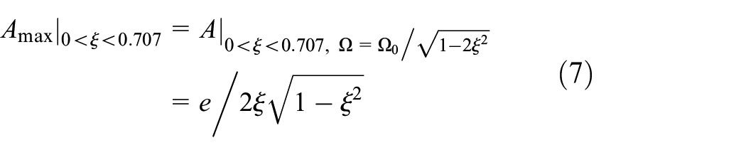
Besides, the rotational frequency at the extreme point is bigger than the inherent frequency:
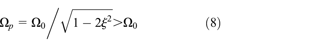
In particular,
The relationship curve of vibration response amplitude and rotational speed is depicted in Figure 2. The conclusions above can also be verified qualitatively and visually. It is depicted that

Relationship curve of vibration response amplitude and rotational speed, with different damping ratio.
Evaluation criteria of ISO 14839 standard
Evaluation of vibration
Reliable operation of an AMB-rotor system requires maintaining running clearance margin, to avoid contact between rotating and stationary parts. Therefore, the maximum value of the vibration (
The corresponding zone table is given in Table 1. It is recommended that a newly commissioned machines would normally fall within Zone A. And machines with vibratory displacement within Zone B are normally considered acceptable for unrestricted long-term operation. The vibratory displacements within Zone C and Zone D are normally considered to be unsatisfactory for long-term continuous operation and be severe to cause damage respectively.
Recommended criteria of zone limits in ISO 14839.

Evaluation of stability
Evaluation of the stability derived from imbalance vibration is specified in ISO 14839-3 standard, 9 which calls for a minimum level of robustness from the viewpoint of AMB control.
With the denotations in Figure 1, the open-loop transfer function of the AMB control system can be expressed as

Then, the sensitivity function

which is chosen as an evaluation index in ISO 14839-3 standard. And the criterion focuses on the peak value of
In ISO 14839-3 standard, it is recommended to inject an excitation signal

which is called input sensitivity.
Connections of the evaluation criteria
The evaluation index of ISO 14839-2 standard is the maximum amplitude of vibration response. As stated by (6) and (7), it is related with eccentric distance and damping ratio. The eccentric distance is an indicator of mass unbalance magnitude as for a certain rotor shaft. And the damping ratio reveals the characteristic of an AMB control system.
As for the evaluation index of ISO 14839-3 standard, sensitivity function is related with the open-loop transfer function according to (10). Thus, it is a characteristic indicator of the AMB control system as well.
In summary, in order to simultaneously implement the two evaluation criteria, the satisfaction of stability margin evaluation is a precondition. That is because the characteristic of an AMB control system is determined when the evaluation criterion of stability is implemented. Afterwards, a constraint of the mass unbalance magnitude is required, and then the evaluation of vibration and stability can be satisfied simultaneously.
Limitations on the evaluation criteria
Even though ISO 14839 standard owns applicable evaluation criteria as for AMB equipped rotating machineries, there are still some limitations on them.
Gyroscopic coupling effect
Gyroscopic effects couple rotor motions in two radial directions and make the system multivariable in nature. To illustrate the problem, decoupled control algorithms are always adopted. 20 However, the gyroscopic systems own very high input sensitivity over a range of operating speeds. Therefore, the measurement of evaluation criteria in ISO 14839-3 standard is not applicable as for systems with strong gyroscopic coupling effects.
Cross coupled stiffness
The coupling between different radial degree of freedom (DOF) may exist as for an AMB-rotor system, which is caused by cross-coupling stiffness. 21 As a result, multivariable nature can be provoked as well. Even a small cross coupled stiffness can make the closed-loop system become unstable. Consequently, a good sensitivity function does not guarantee robustness to cross coupled stiffness.
Design overview and SISO system modeling
Since the evaluation criteria of ISO 14839 standard is aimed at each DOF of an AMB-rotor system, an accurate vibration model of SISO AMB-rotor system is of significance. Therefore, modal analysis is carried out and equivalent mass of SISO system is figured out.
System descriptions
An experimental setup is designed to analyze and verify the theory in this paper, and the schematic diagram is shown in Figure 3. It has two identical 3-DOF permanent-magnet-biased AMB at two ends. The rotor shaft is driven by a permanent-magnet machine in the middle. The inertial coordinate system (X-Y-Z) is established at the mass center S of the rotor shaft. The spans of the two AMB rotors to mass center S are
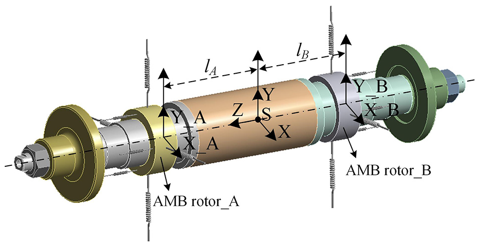
The schematic diagram of the suspended rotor shaft.
The main parameters are listed in Table 2.
Parameters related to the AMB-rotor system.

Modal properties
With the model and parameters stated above, a Campbell chart can be obtained through finite element method, as shown in Figure 4. The two groups of furcated curves represent two kinds of rigid-body-modes, where one of them is a translational motion and the other one is an angular motion. Besides, the solid lines display the forward whirl (FW) and the dashed lines display the backward whirl (BW).
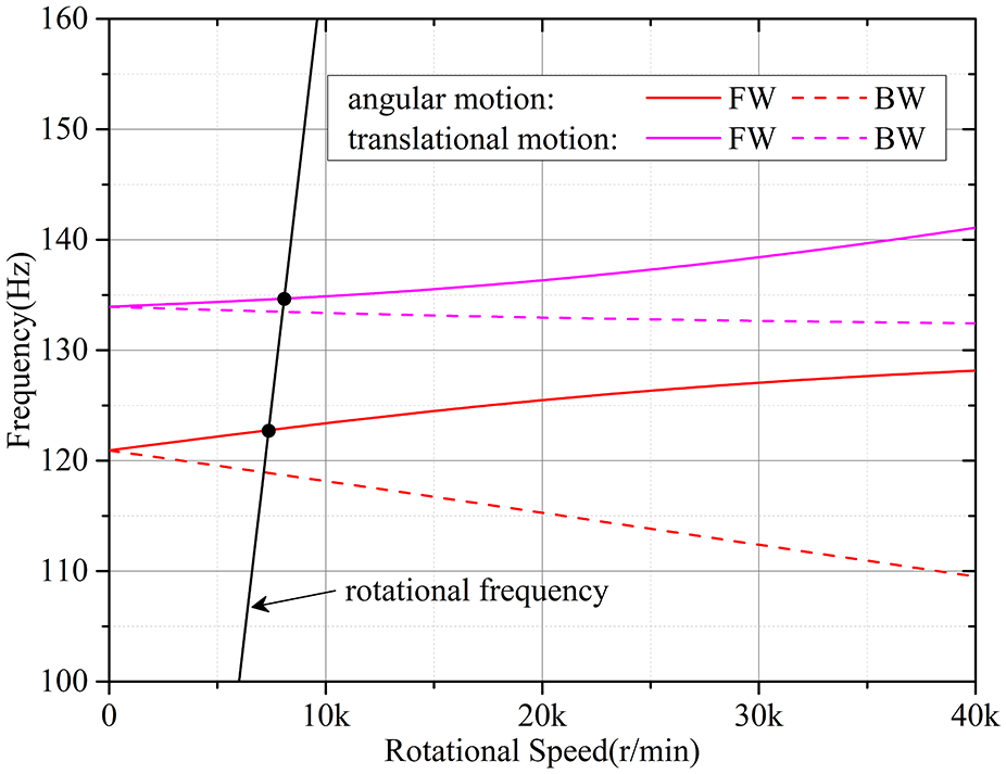
Campbell chart of the AMB equipped rotor shaft.
According to the intersection points between forward whirl lines and the rotational frequency line, it can be concluded that two rigid resonant frequencies are 123 Hz and 135 Hz respectively. Moreover, the furcation is not serious, thus it can be concluded that the gyroscopic coupling effect of the rotor shaft can be neglected.
Then two first natural frequencies and mode shapes are obtained as well, which is shown in Figure 5. Since its first-order bending-critical speed is far beyond the rated speed (833 Hz), the rotor shaft can be regarded as a rigid one.

Bending mode shapes of the two first natural frequencies: (a) first-order: 1604 Hz and (b) second-order: 2992 Hz.
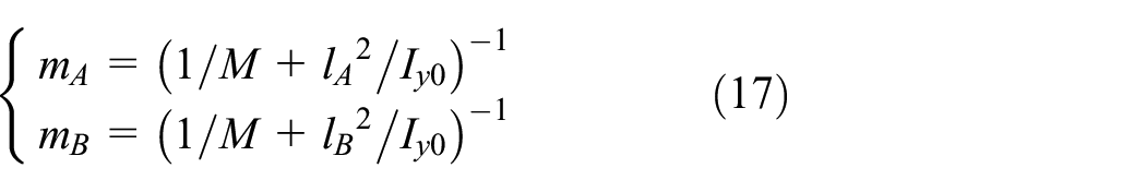
Equivalent mass of SISO AMB-rotor system
As for a rotor shaft with rigid behavior and little gyroscopic coupling effect, it has been shown that decentralized control is well applicable without major deficiencies.
1
In other words, each DOF can be regarded as an SISO system. However, two AMB at two ends support the rotor shaft in radial directions simultaneously. Thus, the mass in the SISO radial motion equation of (1) is not the total mass of the whole rotor shaft, that
The radial motion in X-direction is taken as an example to derive the equivalent mass. Neglecting gyroscopic coupling effects, the dynamical model of the AMB-rotor can be represented as
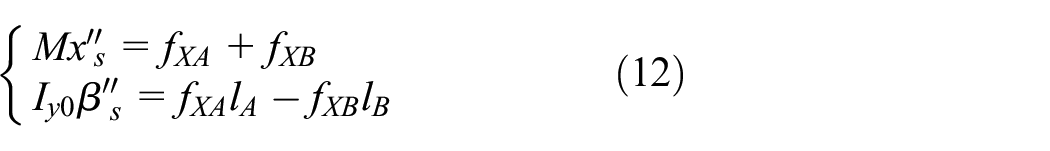
where
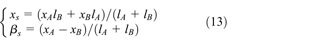
where

Then, the parameters in Table 2 are substituted into (14), and the relations can be obtained that
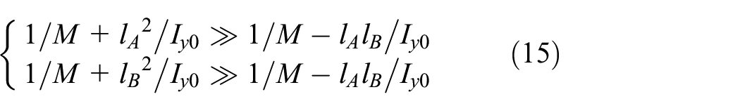
Therefore, (14) can be simplified as
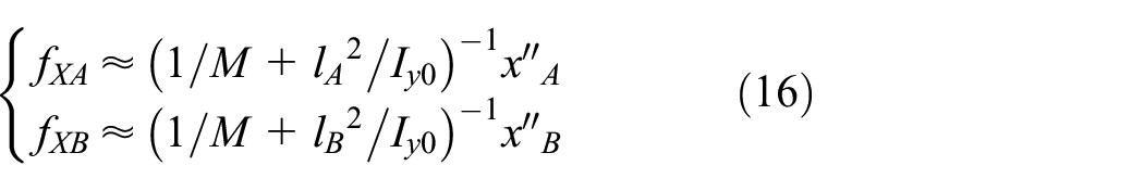
Consequently, the equivalent mass of SISO AMB-rotor can be obtained that
where
The physical essence of the equivalent mass is mass center offset in axial direction of an asymmetric rotor shaft. Therefore, as for a rotor shaft in rotating condition or in static suspension operation, the equivalent mass is constant. Accordingly, with the value of equivalent mass, the imbalance vibration model (4) for SISO decentralized system is more accurate.
Implementation methods of the evaluation criteria
Based on the analysis results of the above sections, sensitivity function is further analyzed. Accordingly, new indices of these evaluation criteria are proposed, which help establish the requirements of controller design and rotor balance quality.
Analysis of sensitivity function
As mentioned in section 2.3, the implementation of stability margin criterion is a precondition as for the two criteria, thus the sensitivity function should be further analyzed.
As for an SISO system, the output sensitivity is identical to input sensitivity, that

The signal
The transfer function of the kinematic equation is

And combined with (3), we can get the expression of the resultant force that

In addition, due to

As a result, with the rotational speed

The maximum value of sensitivity function amplitude is reached when the amplitude of vibration response is the maximum. Thus, combined with (6)–(8), we can get that


Therefore, when
New index of ISO 14839-3 Standard
0.707
According to (23), Zone A defined in ISO 14839-3 standard is achieved if
0
0.707
According to (2) and (8), we can get that

Besides, it is technically easiest to achieve intermediate stiffness. Such a stiffness is always of the same order of magnitude as the negative position stiffness, typically

Then, combined with (7) and (24), we can get that

Consequently, if
As a result, the damping ratio can be regarded as a new evaluation index as for ISO 14839-3 standard, which is figured out as shown in the first two columns in Table 3.
Criteria of zone limits in ISO 14839 with new indices.

New index of ISO 14839-2 Standard
0.707
The maximum value of displacement response is the evaluation index recommended in ISO 14839-2 standard. Besides,
0
0.707
As expressed in (7), the maximum value of displacement response is related with eccentric distance as well as the damping ratio. Thus, the damping ratio which is regarded as a new index of stability evaluation, can be determined according to (27). Then, the eccentric distance can be constrained.
As an example, when Zone A in ISO 14839-3 standard can be achieved, according to (27), the sufficient condition is

Then, if

Zone A in ISO 14839-2 standard can be achieved too. Similarly, other sufficient conditions of achieving different evaluation zones can be figured out.
As a result, the eccentric distance can be regarded as a new evaluation index of ISO 14839-2 standard. As for different zones of ISO 14839-3 standard, the corresponding zone limits are figured out, which are shown in Table 3. Since much high damping ratio is not easy to be achieved, the condition of
Controller design requirements
With the new index of ISO 14839-3 standard that damping ratio, design objective of the AMB controller is explicit. On the one hand, PID control law is the most widely used control logic in industry. On the other hand, the positive stiffness and damping are mainly provided by proportional and derivative actions. Therefore, PD controller is considered here that

Combined with (2), it can be obtained that

which represents the theoretical requirement of controller design. With the parameters in Table 2, the relationship curves of three sets of damping ratios and control parameters are depicted in Figure 6. The three damping ratios are corresponded to the three zone limits in Table 3.

Relationship curve of damping ratio and PD coefficients. (Compliance with requirements of ISO 14839-3).
It can be concluded that, with a proper stiffness, the proportional coefficient is determined. Then with a bigger differential coefficient, bigger damping ratio can be obtained, and a better stability margin is brought about. Therefore, the design and adjustment principles of control parameters are obtained, for implementation of the evaluation criteria in ISO 14939-3 standard.
Balance quality requirements
Since the eccentric distance is regarded as a new index of ISO 14839-2 standard, the only determinant that balance quality should be constrained. According to ISO 21940-11 standard,
11
the balance quality grades

where
Taking Zone A in ISO 14839-2 standard as well as in ISO 14839-3 standard as an example,

Accordingly, the touch-down bearing gap as a function of rotational speed for different balance quality grades can be obtained, as shown in Figure 7.

Permissible balance quality grade with various touch-down bearing gaps. (Compliance with requirements of Zone A in ISO 14839-2 and ISO 14839-3).
It can be concluded that, with a determined balancing speed, if the touch-down bearing gap is smaller, the requirement of balance quality should be more serious. Besides, if the balancing speed is decreased as for a certain rotor shaft, the requirement of balance quality should be upgraded.
Experimental results
Experimental setup
Experiments are developed on a setup as shown in Figure 8, which is an experimental test rig of a magnetically suspended compressor. The rotor shaft is supported by two identical 3-DOF permanent-magnet-biased AMB at two ends, and is driven by a permanent-magnet synchronous machine in the middle. Two-stage turbine disks are replaced by two equivalent disks.

Photograph of the experimental setup.
In the control system, the suspension control algorithm is realized in ARM (STM32F407). The control frequency is set as 12.5 kHz, and the switching frequency of the power amplifier is 50 kHz. The sensors measuring rotor shaft displacements are eddy current sensors, which compose a module with 12 channels. The synchronous machine is powered by an Inovance converter of 22 kW, which is a commercial three-phase inverter.
In this experiment, an intermediate stiffness is chosen according to experience, which is
Case A: P = 1.27*104, I = 1.27*105, D = 12.3. (
Case B: P = 1.27*104, I = 1.27*105, D = 21.7 (
Then, the two cases are shown in Figure 6, from which it can be concluded that Case B owns a better stability margin.
Since the touch-down bearing gap of this test rig is
Measurement of coupling effects
As mentioned in Section 2.4, in order to apply ISO 14839 standard, it is necessary to examine that the setup is not affected by gyroscopic coupling effects and the cross coupled stiffness.
It is well known that gyroscopic coupling effects can provoke the resonant frequency motion. Thus, through frequency sweep excitation, we can obtain the different resonant frequencies at different rotational speeds. Then the influence of the gyroscopic coupling can be determined.
Figure 9 depicts the sensitivity function of X_A near the resonant frequency. It is measured with the control parameters in Case B. As we can see, the resonant frequency changes from 141.6 Hz to 156.0 Hz along with the rotational frequency raising up to 210 Hz, and the changes are small relatively. As a result, it can be concluded that the gyroscopic coupling effect can be negligible.

Sensitivity function of X_A near the resonant frequency.
As for the cross coupled stiffness, its influence can also be determined through frequency sweep excitation. Through comparison between the response magnitude of the principal DOF and that of the other DOF, the influence can be obtained.
Figure 10 shows the different response influences of different DOF under the same excitation in X_A. It is carried out with the control parameters in Case B. It can be found that the magnitude of cross element from other DOF are much smaller than that of the principal DOF, the ratio of which is about 10%. In conclusion, the cross coupling can be negligible as well.
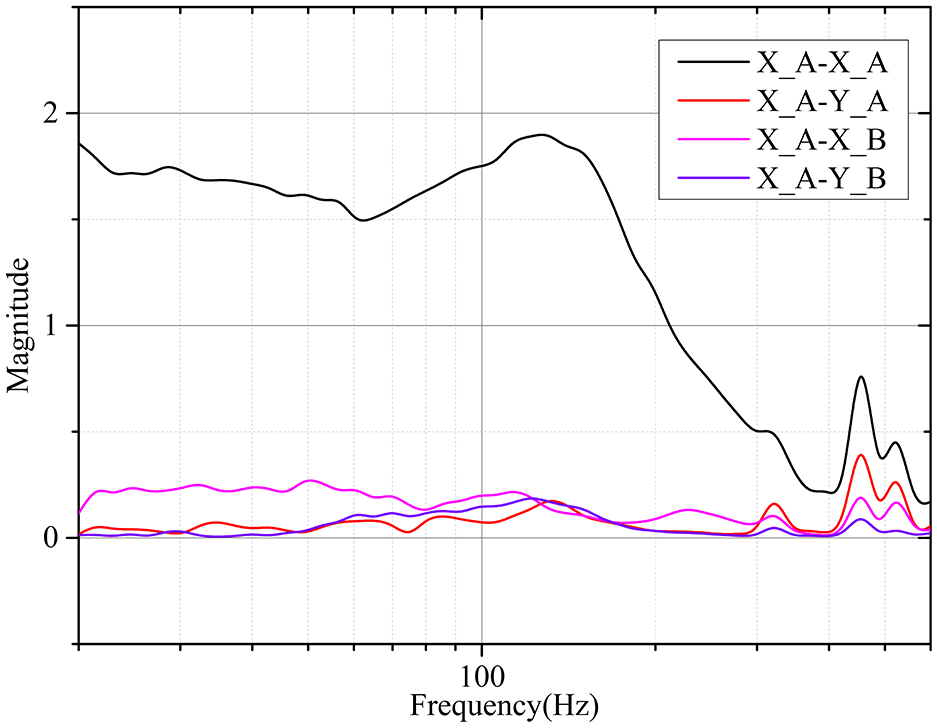
Response magnitude comparison between different DOF under the excitation in X_A.
Results of evaluation
The sensitivity function is depicted in Figures 11 and 12 with different control parameters. In Figure 11, the evaluation result is near the Zone A limit, since the damping ratio is near the zone limit of A/B. Through comparison between Figures 11 and 12, it can be found that the maximum value of sensitivity function is decreased about 30%, since for the bigger damping ratio. Namely, the stability margin is improved in Case B. Moreover, it can also be verified that with bigger damping ratio, the frequency with the maximum value is increased as described as (8).

Sensitivity function with control parameters in Case A.
Sensitivity function with control parameters in Case B.
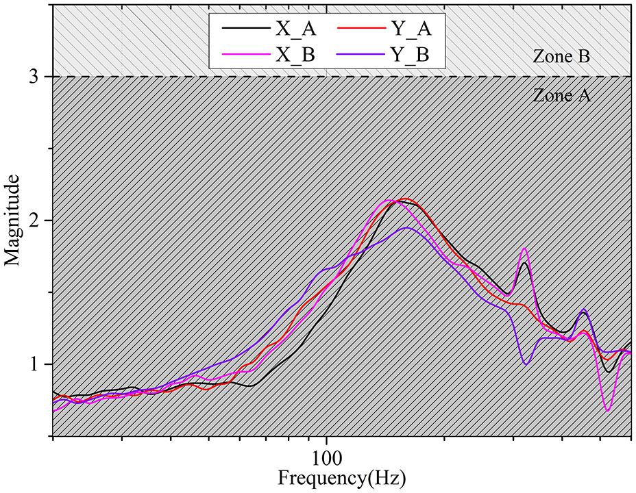
Subsequently, unbalance response data from a test run up to 300 Hz is shown in Figure 13. Even though the sensitivity function requirements and the dynamic balancing are all satisfied, it can be found that Zone A of ISO 14839-2 standard is not achieved in Case A. There are many reasons to bring about the results, such as parameter errors in the system, unbalanced magnetic pull of permanent-magnet motor, and so forth. Even so, the maximum value of unbalance response curve in Case A is near the limit of Zone A. As for Case B, Zone A of ISO 14839-2 standard is achieved, thanking for bigger damping ratio and better stability margin.

Unbalance response curves of the two AMB rotors: (a) control parameters in Case A and (b) control parameters in Case B.
In a word, we can conclude that based on the proposed methods of controller design and dynamic balancing quality constraint, the evaluation criteria of ISO 14839-2 standard and ISO 14839-3 standard can be implemented simultaneously.
Conclusion
This paper presents effective methods to simultaneously implement evaluation criteria of ISO 14839-2 standard and ISO 14839-3 standard. Firstly, imbalance vibration of an AMB-rotor system is modeled to obtain the connections of the evaluation indices in theory. Then in order to obtain an accurate vibration model, the equivalent mass of an SISO AMB-rotor system is derived after the test model is verified to be a rigid shaft with weak gyroscopic effects. The sensitivity function is further analyzed, since the satisfaction of its requirement is a precondition of simultaneous criterion implementation. Afterwards, damping ratio and eccentric distance are derived to be new indices of stability and vibration evaluation respectively. Accordingly, the requirements of controller design and rotor balance quality are established, which are verified through experiments. In a word, the proposed method provides a valid theoretical guidance of design and manufacturing for AMB equipped machineries in industrial applications.
Footnotes
Appendix I
Handling Editor: James Baldwin
Declaration of conflicting interests
The author(s) declared no potential conflicts of interest with respect to the research, authorship, and/or publication of this article.
Funding
The author(s) disclosed receipt of the following financial support for the research, authorship, and/or publication of this article: This research has been supported in part by National Natural Science Foundation of China under grant numbers 51577087, the Funding of Jiangsu Innovation Program for Graduate Education under grant number KYLX16_0359, Fundamental Research Funds for the Central Universities.