
Abstract
Rotodynamic multiphase pumps are usually equipped with many compression units to provide sufficient boosting pressure for the transportation of production fluid in gas oil field. It is a challenge to maintain pump performance while flow parameters in each stage vary due to the compressibility of gas-liquid phase. In this article, a stage-by-stage design method is proposed to improve the boosting capability of a multiphase pump. Variations of flow parameters in each stage are investigated based on computational fluid dynamics (CFD) numerical simulation. Available methods to determinate main impeller geometry parameters of impeller are discussed. The stage-by-stage design method is applied on a five-stage multiphase pump when the inlet gas volume fraction (GVF) are 30% and 50% separately. The second stage is modified base on its corresponding inlet flow parameters when inlet GVF is 30% while the second and third stage are modified when inlet GVF is 50%. Flow parameters, pressure distribution and velocity distribution are compared between the original pump and modified pump. Differential pressure of the modified pump increases by 53.72 kPa and 58.57 kPa respectively when inlet GVFs are 30% and 50%. The feasibility of the stage-by-stage design method is verified through the comparison results.
Keywords
Introduction
In a subsea gas oil field, the production fluid is usually transported from the wellheads to the production facilities through long subsea pipelines and risers. One of the challenges is to keep up a sufficient production rate and the right amount of pressure to flow fluid. Due to this reason, multiphase pumps are widely used in subsea operations to overcome these issues. There are some benefits for the application of multiphase pumps, such as increasing production rate in an existing export pipe-line, reducing well-head flow pressure to increase oil and gas recovery, making it possible to produce hydrocarbon from marginal fields without installing new production facilities and reducing cost of surface facility modification. 1 Helico-axial pumps are the most used among several typical kinds of multiphase pumps including centrifugal pumps, semi-axial pumps and twin-screw pumps. 2 It is a rotodynamic pump with free open hydraulic channels which can accommodate solid particles in the flow. It has the ability to pump fluid with gas volume fraction as high as more than 90%. 3 In order to provide sufficient boosting pressure for the production fluid, a helico-axial multiphase pump is usually equipped with multi-stage which contains dozens or even hundreds of compression units when applied on the subsea gas oil fields. 4 Flow conditions changes obviously in a multi-stage multiphase pump because of the existence and compressibility of gas. The gas-liquid two phase flow patterns inside flow passage of pump vary from isolated bubbles, bubbly flow, gas pocket flow and segregated gas flow as inlet gas volume fraction increases, which could significantly affect the pump performance and brings challenges to maintain the boosting capability of a pump. 5
Therefore, some researches are made to improve the multiphase pump performance. Zhang et al. 6 proposed a multi-objective optimal method for the impeller of a helico-axial multiphase pump with the combination of artificial neural network (ANN) and non-dominated sorting genetic algorithm-II (NSGA-II). Some main geometric parameters such as inlet angle of blade, outlet angle of blade, half cone angle of hub and the hub ratio of import are optimized by applying the optimal method. The experimental results show that the differential pressure and efficiency both increase in the optimized pump. Kim et al. 7 made optimization on the parameters of impeller and diffuser using a multi objective optimization technique by combining the Response Surface Method (RSM) and numerical simulations. The results show that the flow conditions in the flow passage have been improved in the optimized pump and it also shows less energy loss than the base pump. Morrison et al. 8 and Sahand et al. 9 developed a novel electrical submersible pump (ESP) with split vane impellers which aims to increase the gas handling capacity of typical multiphase ESPs up to 70% gas volume fraction. The performance of a three-stage pump has been studied in different operating conditions by experiment. The results show that flow conditions could be improved with homogenized flow and finer bubbles produced by the split vane impellers. It can also help the ESP to delay the surging and gas lock condition until higher gas volume fractions occur. Suh et al. 10 optimized the second stage of impeller and diffuser blades in a two-stage helico-axial multiphase pump by considering the different flow characteristics among the compression units. The hub inlet angle and shroud inlet angle were selected as design variables and optimized using a systematic optimization technique combined with a central composite method and a hybrid multi-objective evolutionary. Liu et al. 11 proposed a novel method to optimize performance of a three stage multiphase pump by theoretical prediction based on Oseen vortex. The velocity moment of flow field downstream diffuser was predicted according to established theoretical model and it is applied to optimize inlet blade angle of next impeller. The pump head and efficiency was respectively improved by 0.29% and 0.19% in average after applying the proposed optimization method. Although many studies have been conducted to maximize the performance of multiphase pumps, most research subjects are single-stage or two-stage pumps. And few of them optimized the geometry parameters in each stage of a multi-stage pump by considering the variations of flow characteristic along the flow direction under relative high inlet gas volume fractions and higher rotational speeds. Actually, as early as in the 1990s, the P302 Poseidon pump 12 has been designed to adjust the nominal flow capacity of the hydraulic cells to the flowrate reduction resulting from the gas compression. It was composed of 15 compression units in three series of five identical stages. The external diameter of all series were the same. The two first series had identical internal diameter but their blade profiles were different. The internal diameter of the third series is a little larger than the first ones in order to reduce the channel section. However, the method to determine the geometry parameters of these different series is still not disclosed.
In this paper, the stage-by-stage design method is proposed based on the corresponding flow parameters at the import of each stage in a multi-stage multiphase pump. This method is applied on the hydraulic design of a five-stage helico-axial multiphase pump under both low and high inlet gas volume fractions and high rotational speeds. The flow characteristics such as flow parameters, pressure distribution and velocity distribution are investigated in the modified multi-stage pump by numerical simulations. Comparisons of pump performance are made between the modified pump and the based pump.
Geometry and numerical simulation method
A multi-stage helico-axial pump is composed of several axial compression units or stages assembled in line. The main flow direction is parallel to the pump axis. Each stage consists of an impeller which is mounted on a rotating shaft and a fixed diffuser. The design parameters of the five-stage multiphase pump are: volume flow rate 100 m3/h and rotational speed 4500 r/min. More design specifications of the multiphase pump are shown in Table 1. For the numerical simulations, the three-dimensional model of impeller and diffuser are both generated by ANSYS BladeGen. The assembly of the five-stage pump investigated in this paper is shown in Figure 1. In order to make sure the flow through inlet and outlet of the pump be steady, the two extend parts are added at the inlet and outlet, separately. The high quality structured hexahedral grids for impeller and diffuser are generated by ANSYS Turbogrid 17.2. Figure 2 shows the mesh of impeller and diffuser. The mesh of inlet and outlet extend part are generated by ANSYS ICEM. The gird number of impeller domain is about 453,000 whereas that of the diffuser domain is about 537,000.
Design specifications of multiphase pump.


Geometry of the five-stage pump.

The hexahedral grids of impeller and diffuser: (a) impeller and (b) diffuser.
The computational fluid dynamics (CFD) simulation is conducted using the commercial fluid analysis program ANSYS CFX. The three-dimensional (3D) Reynolds-averaged Navier–Stokes (RANS) equation was solved for turbulent flow analysis to investigate the flow field characteristics inside the multiphase pump. The governing equation used was discretized with the finite volume method (FVM). 13 A high-resolution scheme with second-order accuracy was used as the discretizing scheme. 14 As to the boundary conditions, velocity conditions are imposed on the pump inlet and the values of gas volume fraction and water volume fraction are both set. Static pressure conditions are given for the pump outlet. The no-slip velocity condition is imposed on the walls such as shroud and hub of impellers and diffuser. The frozen-rotor technique are set for interfaces between impeller and diffuser in each stage while the stage-average method is applied to those between other domains. The Eulerian-Eulerian two-fluid approach is typically used to analyze internal multiphase flow of the pump15–18 in the numerical simulation. It contains the homogenous and inhomogeneous types depending on the approach. In a helico-axial multiphase pump, the two-phase flow is predominated by the centrifugal force. The dispersed phase (gas) accelerates relative to the continuous phase (water) due to the density differences. So the inhomogeneous multiphase model is applied. It refers to the case where separate velocity fields exist for each fluid. The pressure field is shared by all fluids. The particle model performs analysis under the assumption that the particles of each phase are maintained independently. 19 The shear stress transport (SST) k-omega turbulence model 20 is used for water phase while dispersed phase zero equation turbulence model is used for gas phase. 21 The two-phase flow is simulated under isothermal conditions without heat and mass transfer between the continuous and the dispersed phases. So the energy conservation equation can be ignored and no source or diffusion terms appear in the mass balances. The residual target for the convergence criteria is 10−4. The laws of conservation of inhomogeneous momentum and mass equation can be can be found in ANSYS official tutorial. 22 They are not listed in the paper. Since the fluid domain and numerical simulation method used in this paper are both the same as those in Shi et al.,23,24 which including the validation of numerical simulation method. The details are not shown here again.
Stage-by-stage design of a five-stage multiphase pump
The stage-by-stage design method is investigated based on the numerical simulation results of the five-stage multiphase pump in the following part. Variations of inlet flow parameters in each stage of the multi-stage pump are presented to prove the necessity of design the impeller in a certain stage according to its responding inlet flow parameters. Then the available methods to determine some main impeller geometry parameters are discussed.
Variations of flow parameters in each stage of a five-stage pump
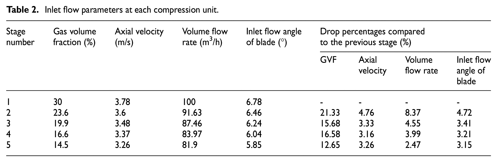
Due to the compressibility of gas, flow parameters such as volume flow rate, pressure and gas volume fraction vary at the inlet of each stage along the flow direction. Based on the numerical simulation results, the gas volume fraction, axial velocity, volume flow rate and inlet flow angle of blade on impeller shroud at the inlet of each stage of a five-stage multiphase pump are shown on Table 2. The flow conditions are inlet volume flow rate 100 m3/h, inlet gas volume fraction 30% and rotational speed 4500 r/min. Table 2 shows that the given inlet flow parameters both decrease from the first stage to the last stage. The drop percentages of flow parameters between adjacent stages obviously indicates that there are large variations for the inlet gas volume fraction. Because the gas volume fraction is directly related to gas compressibility. The axial velocity, volume flow rate and inlet flow angle of blade on impeller shroud both decrease but the drop percentages are relatively small compared to the inlet gas volume fraction. As the degree of further compression in the subsequent pump stages is reduced. The drop percentages of flow parameters between adjacent stages also decrease.
Inlet flow parameters at each compression unit.
Determination of the main impeller geometry parameters
Since impeller is the main component in a compression unit, it is mainly focused on the modification of impeller parameters. The shroud diameter, hub ratio of import, half cone angle of hub, number of blades, inlet angle of blade and axial length of impeller are the main geometry parameters. Inlet hub diameter is related to hub ratio of import and affects the size of impeller flow channel. The change of those geometry parameters has influence on the flow conditions as well as the pump performance. The degree to which each design variable affects pump performance was evaluated by Kim et al. 25 using 2k fractional factorial design. The effects of individual design variables of impeller on pump performance were analyzed. The results show that impeller hub inlet angle, impeller shroud inlet angle and impeller shroud outlet angle have large effects on total pressure rise and efficiency of the pump. They are selected as the final design variables in that research.
In this paper, the hub ratio of import and impeller shroud inlet angle are selected to be mainly modified for the stage-by-stage design of the five-stage pump. The design flow condition of the five-stage pump is that volume flow rate 100 m3/h, rotational speed 4500 r/min and inlet gas volume fraction 30%. The second stage is firstly redesigned according to its corresponding inlet flow parameters. The following part is to determine the values of hub ratio of import and impeller shroud inlet angle.
Inlet hub ratio of impeller
Since the volume flow rate at the import of each stage is decreased along the flow direction due to the gas compressibility. In order to make sure the geometry parameters especially the channel size of the posterior stage be consistent with the decreased volume flow rate, the cross-sectional area of impeller channel should also be decreased. In this paper, the impeller shroud diameters of each stage are constant and kept the same. So the impeller hub diameters of the subsequent stages should be increased. Hub ratio of import is the ratio between hub diameter and shroud diameter of impeller. The following work is to calculate hub ratio of import according to the volume flow rate. However, there is not a theoretical method currently to determine hub ratio of import during the process of hydraulic design for an impeller. The common way is to select an empirical value within a reasonable range. In the following part, three available methods are proposed to calculate the hub ratio of import separately. Then make comparison of the three values and determine the final value.
(1) Method based on the consistent of axial velocity
The inlet axial velocity of impeller decreases along the flow direction in the five-stage multiphase pump due to the gas compressibility which leads to the reduction of volume flow rate at the import of each stage. Thus, the kinetic energy also decreases and the portion converted to pressure energy is decreased which affects the pump boosting ability. 26 The inlet axial velocity at the first stage is 3.78 m/s while it decreases to 3.6 m/s in the second stage. In order to obtain sufficient kinetic energy, the axial velocity in the second stage is set to 3.78 m/s. Based on the equation (1) of axial velocity and the equation (2) of hub ratio, the relationship between hub ratio and axial velocity is shown in equation (3).
The equation to calculate axial velocity is shown in equation (1).


Based on equation (1) and (2), the hub ratio is shown in equation (3).

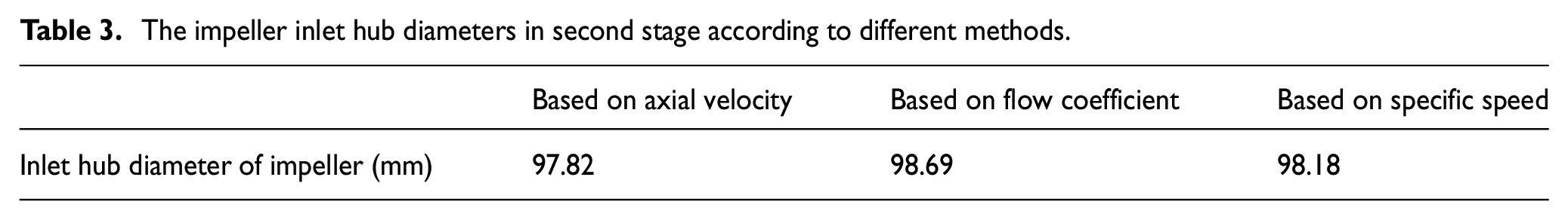
The volume flow rate Q is 91.63 m3/h, axial velocity vm is 3.78 m/s at the import of the second stage. The impeller shroud diameter Dt is 135 mm. Then the hub ratio of import htr is 0.724 and inlet impeller hub diameter in the modified second stage is 97.82 mm.
(2) Method based on the consistent of flow coefficient
According to the similarity theory, 27 the designed pump and the based pump both fulfill the conditions of geometric, kinematic, and dynamic similarities. The geometry parameters of designed pump could be determined according to the flow coefficient and head coefficient based on the geometry parameters of the based pump. The flow coefficient can be calculated by equation (4).

Where,

The relationship between inlet shroud diameter of impeller Dt, flow coefficient

(3) Method based on the specific speed
The specific speed is a characteristic coefficient derived from the similarity conditions which allows a comparison of impellers of various pump sizes even when their operating data differ. 28 It is considered that there is an inverse proportional relationship between the hub ratio and specific speed which is shown in equation (7). It is further simplified to show the inverse proportional relationship between hub ratio and volume flow rate in equation (8).


The inlet hub diameter of impeller in the second stage calculated by the above three methods are shown in Table 3. There is not much difference among these three values, which verifies the feasibility of the above methods. After comprehensive analysis and comparison, the inlet hub diameter of impeller in the second stage is set to 98 mm.
The impeller inlet hub diameters in second stage according to different methods.
Inlet angle of impeller shroud
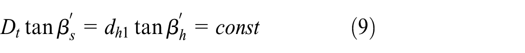
The inlet impeller angle should be decreased to reduce the shock flow loss at the import of impeller. The impeller shroud inlet angle
Where
Other main geometry parameters
Table 4 shows the main structure parameters of impeller in the modified second stage which including the outlet shroud diameter and blade numbers.
Main structure parameters of impeller in the second stage.

The main geometry parameters of diffuser in the modified second stage are determined based on those of the impeller. They are shown in Table 5. The geometry parameters of the third stage to the last stage are the same as those of the second stage. With the design flow condition inlet GVF 30%, volume flow rate 100 m3/h and rotational speed 4500 r/min, the outline of meridional plane in the modified five-stage multiphase pump by applying the stage-by-stage design method is shown in Figure 3. It includes some main geometry parameters of impeller blade and diffuser blade. The z axis represents the central position of pump along the flow direction and r axis is the radial axis. The cross-section flow area decreased from the first stage to the second stage which is corresponding with the reduction of volume flow rate along the flow direction.
Main structure parameters of diffuser in the second stage.


Outline of the modified five-stage multiphase pump.
Comparison of performance between the modified pump and the based pump
In order to easily make expression and distinguish, the five-stage multiphase pump with the same geometry parameters in each stage is named the based pump. While the five-stage pump with different geometry parameters after applying stage-by-stage design method is named the modified pump. The comparison of performance between modified pump and based pump are implemented at the same inlet flow conditions (volume flow rate 100 m3/h, rotational speed 4500 r/min, inlet GVF 30%) by numerical simulations. The variation characteristics of flow parameters, pressure distribution and velocity distribution in each stage are also investigated.
Comparison of flow parameters at each stage
The variations of inlet volume flow rate and inlet flow angle at impeller shroud in each stage are compared between the modified pump and based pump. Table 6 shows the value of flow parameters at the inlet of the each stage. It can be seen that the volume flow rate in modified pump is less than that in the based pump at the same stage from the second stage to the last stage. It indicates that the compression capacity to gas in the two-phase flow is improved in the second and subsequent stages. The compression degree is decreasing as the stage increases. The same conclusion can be concluded for the inlet flow angles of blade. The inlet flow angles of blade on impeller shroud are increased from the second stage to the fifth stage in the modified pump, which indicates the shock flow loss at the import of each stage is reduced.
Inlet flow parameters in the modified pump and original pump.

Comparison of pressure distribution
Figure 4(a) and (b) show the pressure distributions on the blade-to-blade plane at the mid-span surface of the based pump and modified pump separately. Through the comparison, it can be concluded that the pressure distribution is generally more uniform in the whole flow passage. The obvious pressure surge occurs between the impeller and diffuser on the fifth stage in the based pump while it does not appear on the same position in the modified pump. It indicates that the flow conditions in the subsequent compression units are improved in the modified pump through the stage-by-stage design. Thus, the whole differential pressure of the modified pump is higher than that of the based pump.

Pressure distribution on the blade-to-blade plane at the mid-span surface: (a) the based pump and (b) the modified pump.
Comparison of velocity distribution
The comparison of velocity distribution at leading edge of impeller blade on the blade-to-blade plane at the mid-span surface in each stage between the based pump and modified pump is shown in Figure 5. Figure 5(a) shows the velocity distribution in the based pump. The velocity direction at the leading edge of blade matches with the blade angle in the first stage while the deviation occurs in the second stage. The red lines on the second stage is the direction of velocity. The velocity direction changes on the leading edge close to the suction side of blade compares to that in the first stage. It also occurs on the same position from the third stage to the last stage in the based pump. This mainly due to the mismatch between the import flow parameters and geometry parameters in each stage, which causes shock flow losses. Figure 5(b) shows the velocity distribution in the modified pump. The red lines represent velocity direction at leading edge of blade in the second stage. It shows the deviation of velocity direction on the suction side of blade disappears. The velocity direction also matches well with the blade angle in the subsequent stages.

Velocity distribution at leading edge of impeller blade on the blade-to-blade plane at the mid-span surface in each stage: (a) the based pump and (b) the modified pump.
The gas-liquid two phase flow conditions in the flow passage of the modified pump is improved from the comparison of pressure distribution and velocity distribution between the based pump and modified pump. The pump performance is also developed. With the design conditions that volume flow rate is 100 m3/h, rotational speed is 4500 r/min and inlet GVF is 30%, the differential pressure of based pump is 903.64 kPa and it increases to 957.36 kPa in the modified pump. It verifies the feasibility and effectiveness of the stage-by-stage design method for the five-stage multiphase pump. It should be mentioned that since the variations of inlet volume flow rate and flow angle on the impeller shroud from the second stage to the third stage are not obvious in the modified pump, it is enough to just modified the second stage under the current design conditions and the geometry parameters of the third stage to the fifth stage are the same as those of the second stage.
Stage-by-stage design of multiphase pump under high inlet GVFs
The flow conditions such as inlet GVFs vary in real working conditions on gas oil field. It is very possible for helico-axial multiphase pumps to work under high inlet GVFs conditions. So it is necessary to consider the redesign of the five-stage pump in high inlet GVFs condition based on the stage-by-stage design method. In the following part, the stage-by-stage design method is applied on the multiphase pump under the condition that rotational speed is 4500 r/min, volume flow rate is 100 m3/h and inlet GVF is 50%.
Redesign of the second stage
Table 7 shows the import flow parameters of each stage when the inlet GVF is 50%. They are both decreased along the flow direction from the first stage to the last stage. The second stage in the five-stage pump is modified firstly according to its corresponding import flow parameters. Based on the previous three methods which have been investigated to determine the import hub ratio, the import hub ratio of impeller in the second stage is calculated under the current conditions. Then the inlet hub diameter is set to 100 mm and inlet angle on impeller shroud is set to 6.8°. The geometry parameters of the third stage to the fifth stage are the same as those of the modified second stage.
Flow parameters in each stage of the original pump (inlet GVF = 50%).

The import parameters of each stage in the modified five stage with new second stage are calculated by numerical simulations. The parameters setting is the same as previous numerical simulation. Table 8 shows the flow parameters at the import of each stage. Volume flow rates and GVFs are both decreased in each stage compared with those in the original pump, which indicates the improvement of compression ability. As to the inlet flow angles on impeller shroud, they both increase in the second and following stages, which shows the decrease of shock flow angles as well as the shock flow loss.
Flow parameters of each stage in the modified pump with the new second stage (inlet GVF 50%).

Figure 6 shows the comparison of pressure distribution at the impeller leading edge on impeller hub between the modified pump with new second stage and the original pump. In Figure 6(a), the pressure distribution is uniform at the leading edge in the first stage. While the local maximum pressure point moves from the center to the pressure side of blade in the second and following stages which makes the pressure distribution not uniform at that part. Figure 6(b) shows the pressure distribution at the same area in the modified pump with the new second stage designed by the stage-by-stage design method. The pressure distribution in each stage has been obviously improved and becomes uniform.

Pressure distribution at the impeller leading edge in original pump and modified pump with the new second stage: (a) original pump and (b) modified pump with new second stage.
In order to sufficiently investigate the variations of internal flow characteristics between the modified pump and original pump, the velocity distribution on the meridional plane of blade on each stage are compared. Figure 7 shows comparison of the first three stages. There are radial velocity components at the import and middle area near impeller shroud both in the first stage of modified pump and original pump. The reversal flow also occurs at that part. In the second stage of original pump, the reversal flow at the import disappears while there are radial velocity components which point to the impeller hub. But it doesn’t occur at the same position in the modified pump which indicates the improvement of flow conditions after redesign of the second stage. The radial velocity component also occurs at the import of the third stage in original pump. Although the velocity is axial at impeller inlet in the third stage of modified pump, the reversal flow occurs again at the middle part of impeller shroud. Figure 8 shows the comparison between the last two stages. Velocity distributions are generally normal in the original pump while reversal flow still exists in the last two stage of modified pump.

Velocity distribution on the meridional plane of blade in the modified pump and original pump (the first three stages): (a) original pump and (b) modified pump with new second stage.

Velocity distribution on the meridional plane of blade in the modified pump and original pump (the last two stages): (a) original pump and (b) modified pump with new second stage.
Although it shows the improvement of pressure distribution and flow conditions by modifying the second stage through the comparison of inlet flow parameters, pressure distribution and velocity distribution of each stage between the modified pump with new second stage and the original pump, the velocity distributions on the meridional plane of blade from the third stage to the fifth stage in the modified pump become worse than those in the original pump. It is necessary to continue to redesign the third stage based on the modified pump.
Redesign of the third stage
Redesign of the third stage is implemented based on the inlet volume flow rate and GVF shown in Table 8. The methods to determine main geometry parameters are the same as those have been applied on the second stage. The inlet hub diameter of impeller in the third stage is set to 103 mm and the inlet flow angle on shroud is set to 6.5°. Main geometry parameters of the new third stage are shown in Table 9. The fourth and fifth stage are the same as the new third stage. Figure 9 shows the outline of modified five-stage multiphase pump with the third stage redesigned. Inlet hub diameters of the first three stages are 94.5 mm, 100 mm, and 103 mm, separately. The inlet hub diameters of the last two stages are both 103 mm.
Structure parameters of impeller in the third stage (inlet GVF = 50%).


Outline of the modified five-stage multiphase pump with the third stage redesigned inlet GVF = 50%).
Numerical simulations are implemented on the modified five-stage pump with new third stage under the condition inlet volume flow rate 100 m3/h, rotational speed 4500 r/min and inlet GVF 50%. Table 10 shows the volume flow rate, inlet GVFs and inlet flow angle on impeller hub of each stage calculated based on numerical results. Compared to the aforementioned modified pump with the second stage redesigned, the inlet volume flow rate and GVFs decreases further at the same stage in current modified pump with new third stage. The inlet flow angle on impeller shroud increases and the shock angle reduces further. It shows that the inlet flow conditions of each stage are significantly improved in current modified pump.
The inlet parameters of each stage in the modified pump with first three stages redesigned.

Figure 10 shows the pressure distributions at the leading edge of impeller in the modified pump with the second and third stage redesigned. The pressure distribution is generally uniform and symmetrical at the leading-edge area. They are similar with those of the modified pump with the second stage redesigned shown in Figure 6. The velocity distribution on the meridional plane of impeller blade of each stage in the modified pump is shown in Figure 11. Comparing with those on the modified pump with the second stage redesigned shown in Figures 7 and 8, there are no reversal flow on the third and fourth stage in the newly modified pump and the velocity direction is consistent with the fluid flow direction. Although radial velocity component occurs at the middle position of impeller shroud in the fifth stage, the flow conditions have been greatly improved compared to that on the same stage of previous modified pump in Figure 8. The flow conditions in the whole five-stage become better in the newly modified pump compared with the previous pump. Under the same design conditions, the differential pressure is 632.7 kPa and efficiency is 34.58% for the original five-stage pump with all the stage are the same. While they are increased to 691.27 kPa and 36.11% separately in the modified pump with the second and third stage changed.

Pressure distribution at the impeller leading edge in the modified pump with the second and third stage redesigned.

Velocity distribution on the meridional plane of blade in the modified pump with the second and third stage redesigned.
Conclusion
Authors should discuss the results and how they can be interpreted in perspective of previous studies and of the working hypotheses. The findings and their implications should be discussed in the broadest context possible. Future research directions may also be highlighted.
A stage-by-stage design method is proposed in this paper based on the variation characteristics of flow parameters in a five-stage multiphase pump. The available methods to determine the inlet hub diameter of impeller and other main geometry parameters are investigated. The stage-by-stage design method is separately applied on the five-stage pump when inlet GVFs are 30% and 50%. Performance and flow characteristics such as pressure distribution and velocity distribution are compared between the modified multiphase pump and the original one. The following conclusions are made:
Flow parameters such as volume flow rate, GVF and flow angle at the inlet of each stage in a multi-stage multiphase pump vary along the flow direction, which is mainly due to the gas compressibility of the gas-liquid flow. Therefore, it is necessary to modify the geometry parameters of each stage based on its corresponding inlet flow parameters to improve the pump performance.
The inlet hub ratio and impeller blade angle are the main geometry parameters which significantly affect pump performance. By modifying the main geometry parameters of each stage based on the corresponding inlet flow parameters, the performance and flow conditions of modified pump could be improved obviously. It verifies the feasibility of the stage-by-stage design method.
As to the stage-by-stage design of a five-stage multiphase pump, it is necessary to consider the gas compressibility in each stage with different inlet GVFs. When the inlet GVF is not very high such as 30%, the variation of flow parameters in each stage especially the subsequent stages is not obvious since the gas compressibility degree is low. In this case, it is enough to just redesign the second stage and the following stages are the same as the modified second stage. While when the inlet GVF increases to 50%, the gas compressibility degree is also developed, the second and third stage both should be modified under that condition. And the fourth and fifth stage are the same as the modified third stage. When the inlet GVFs are extremely low (10%) or high (90%), it is not necessary to apply the stage-by-stage design method. Overall, whether to modify a certain stage is mostly depended on the inlet GVF and variations of the corresponding flow parameters.
Footnotes
Appendix
Handling Editor: James Baldwin
Author contributions
Y.S. wrote the paper, made the hydraulic design and numerical simulations; H.Z. determined the structure of this paper and gave suggestions for the improvement of the paper.
Declaration of conflicting interests
The author(s) declared no potential conflicts of interest with respect to the research, authorship, and/or publication of this article.
Funding
The author(s) received no financial support for the research, authorship, and/or publication of this article.