
Abstract
Forced convective heat transfer and thermo-hydraulic efficiency in the heat exchanger square channel (HESC) inserted with 10° wavy thin rib (WTR) are reported numerically. The effects of rib height, pitch distance and flow velocity on flow and heat transfer profiles are considered. The rib height to the channel height; e/H or HR, is varied in the range 0.05–0.30, while the rib pitch to the channel height; P/H or PR, is varied in the range 0.50–1.25. The air velocity in the HESC inserted with the WTR is considered in terms of Reynolds number. The Reynolds numbers (Re = 100–2000) for the present investigation is analyzed at the inlet condition. The finite volume method (commercial code) with SIMPLE algorithm is picked to solve the present problem. The numerical model of the HESC inserted with the WTR is validated for both grid independence and verification of the smooth HESC. The numerical results of the HESC inserted with the WTR are printed in terms of flow and heat transfer profiles. The values of Nusselt number, friction factor and thermal efficiency factor in the HESC inserted with the WTR are also plotted. As the numerical result, it is found that the WTR in the HESC can produce the vortex flow that the reason for the enhancements of heat transfer and efficiency. The increment of the heat transfer ability in the HESC is detected when increasing rib height and Reynolds number. In addition, the greatest thermal efficiency factor in the HESC inserted with the WTR is around 3.43 at HR = 0.20, PR = 1, and Re = 2000.
Introduction
Due to the need of high thermal efficiency for heat exchangers, the developments of the heating system had been widely tested. The thermal efficiency enhancement in the heat exchangers for many industries with passive method had been examined by various researchers. The passive method does not need the external energy or power into the heat transfer system. The passive method for the enhancement of heat transfer in the heating section is to insert the vortex generator or turbulator on the heat transfer surface to generate the vortex flow. The generation of the vortex flow will disturb the thermal boundary layer that is the important reason for the augmentation of the heat transfer ability and thermal efficiency.1,2 The investigation on heat transfer ability and thermal efficiency in the heat exchangers can be done both experimental and numerical methods. The credibility of the experimental result is higher than the numerical result, while the numerical study can help to describe the flow and heat transfer patterns in the tested section. The understanding on flow and heat transfer mechanisms in the heat exchanger is very important for the development of the heat exchanger. The numerical study also helps to save cost and human resource when compared with the experimental investigation.
The examples of the numerical and experimental investigations for the thermal efficiency improvement in various types of the heat exchanger with passive method were reported by many researchers. Bahiraei et al. 3 selected the V-shaped rib with nanofluid to enhance heat transfer rate in a square channel. The influences of rib pitch, rib height and flow attack angle on flow and heat transfer characteristics were considered. They concluded that the large rib height with small rib pitch brings lower energy destruction and augments the second law efficiency. Bahiraei et al. 4 numerically investigated the thermo-hydraulic performance in a square channel with 90° V-rib and Cu-water nanofluid. The impacts of rib configurations and rib pitch on heat transfer behavior were considered. Bai et al. 5 reported the numerical investigation of ribs disturbed entrance effect of pressure loss and heat transfer in pin-fin array. The three different configurations of ribs were compared for the Reynolds number around 7000–40,000. They stated that the numerical study can help to describe the flow topology in the tested section. They concluded that the entrance effect not only enhances heat transfer ability, but also reduces the pressure loss of the pin-fin array. Wang et al. 6 reported both numerical and experimental investigations on flow configuration and heat transfer structure in the microchannel heat sink with bidirectional rib. They claimed that the microchannel heat sink with vertical rib and spanwise rib perform the Nusselt number higher than the general type around 1.40–2.00 and 1.20–1.42 times, respectively. Luan et al. 7 studied the effect of connecting holes on flow structure and heat transfer ability in a two-pass channel with and without rib turbulators for the Reynolds number of 10,000, 30,000, and 50,000. They found that the pressure drop can be reduced around 14.66% at the heat transfer loss around 1.68% for the smooth channel, while the pressure loss can be dropped around 47.99% with the heat transfer loss around 8.24% for the channel installed with rib. Liu et al. 8 concluded the effects of rib arrangement on thermal performance of a parabolic trough receiver with ribbed absorber tube. They detected that the Nusselt number of ribbed tube is higher than the general type around 1.41–3.21 times. Bahiraei et al. 9 summarized that the overall heat transfer coefficient, effectiveness and heat transfer rate of the heat exchanger increase when augmenting rib height and decreasing rib pitch. Li et al. 10 studied the heat transfer rate and pressure drop in channels with miniature structured ribs for turbulent flow (Re = 10,000–60,000). The rib configuration; transverse rib, angled rib, V-shaped rib, and W-shaped rib, were compared both experimental and numerical studies. They reported that the W-shaped rib gives the highest heat transfer rate, while the angled rib performs the opposite result. They concluded that the globally averaged Nusselt number and overall Nusselt number are around 2.20–2.60 and 2.90–3.30 times above the smooth channel, respectively. The numerical investigation on flow pattern and heat transfer behavior of pin-fin array with rib turbulators was reported by Bai et al. 11 They found that the heat transfer rate of pin-fin array increases when installing rib turbulators. They claimed that the 90° rib provides the best overall performance. Chai et al. 12 analyzed the thermal performance in microchannel heat sink with triangular ribs on sidewalls. The impacts of rib geometry and arrangement on heat transfer and thermo-hydraulic performance were considered for the Reynolds number around 187–715. They detected that the microchannel heat sink with aligned triangular ribs brings the Nusselt number and friction loss around 1.03–2.01 and 1.06–9.09 times above the general type, respectively, while the microchannel heat sink with offset triangular ribs gives the heat transfer rate and pressure loss around 1.01–2.16 and 1.04–7.43 times higher than the plain channel, respectively. The investigation of flow configuration and heat transfer behavior of supercritical pressure carbon dioxide in pipes with discrete double inclined ribs was reported by Yuan et al. 13 Wang et al. 14 studied the heat transfer configuration in a microchannel heat sink with truncated rib on sidewalls for the Reynolds number around 100–1000. The effects of rib configuration, rib arrangement and rib width on heat transfer were analyzed. Patel et al. 15 presented the thermo-hydraulic performance improvement in a solar air heater roughened with reverse NACA profile ribs. The influences of relative roughness pitch and relative roughness height were studied for Re = 6000–18,000. They concluded that the optimal thermal performance is around 2.53 at the Reynolds number around 6000. Ahmed et al. 16 picked the triangular rib with nanofluid to improve heat transfer rate in a duct. The effects of nanoparticles type, nanoparticles volume fraction, nanoparticles diameter and Reynolds number were analyzed numerically. Zheng et al. 17 numerically investigated the convective heat transfer and flow structure in a rectangular channel with convergent and divergent slit rib for the Reynolds number around 10,000–25,000.
In the present work, the numerical investigation on flow pattern and heat transfer behavior in the heat exchanger square channel (HESC) inserted with passive technique is reported. The rib turbulator with wavy configuration, which is called “wavy thin rib (WTR),” is selected to enhance heat transfer ability and thermal efficiency of the HESC. The rib type vortex generator has high effectiveness to develop the heat transfer ability and thermal efficiency in the HESC. The wavy configuration likes as V-shaped and W-shaped ribs is prominent structure for the creation of the impinging flow that is an important mechanism to enhance heat transfer ability. The main objectives for the creation of the WTR in the present work are to augment heat transfer ability and thermal efficiency. Moreover, the convenience of the installation, forming and maintenance is also considered. The WTR may produce many cores of the vortex flow, that helps to a better fluid mixing or turbulent mixing in the HESC. The numerical results of the present research are reported in terms of flow topology and heat transfer mechanisms in the HESC. The thermal efficiency analysis in terms of Nusselt number, friction factor and thermal efficiency factor (TEF = (Nu/Nu0)/(f/f0)1/3) of the HESC inserted with the WTR is also concluded. The influences of the WTR dimension and pitch spacing on flow and heat transfer configurations for laminar regime, Re = 100–2000, are discussed. The present results on friction loss, heat transfer rate and thermal efficiency factor are also compared with the previous research. The thermal efficiency factor with various parameters of the current work is plotted in the figure of contour plot. The contour plot of thermal efficiency factor can be an important knowledge to help to design the heating section with high thermal efficiency and also help to select the parameters of the vortex generator.
Physical model of HESC equipped with WTR
The computational domain of the HESC placed with the WTR is generated by the commercial program. The numerical model of the HESC inserted with the WTR is illustrated as Figure 1. The square channel height, H, is set around 0.05 m.1,2,18–24 The hydraulic diameter of the square channel, Dh, is equal to the square channel height or Dh = H. The WTRs (likes as wavy orifices) are installed in the HESC as the figure. The WTR height and WTR pitch represent with “e” and “P,” respectively. The WTR heights to channel height, e/H or HR, is varied in the range 0.05–0.30. The pitch to channel height, P/H or PR, is varied in the range 0.50–1.25. The Reynolds number based on the hydraulic diameter and inlet condition around 100–2000 (laminar regime) is considered for the present research. The flow attack angle of the WTR is fixed for all investigations around 10°. The periodic length of the computational domain for the HESC installed with the WTR, L, is equal to pitch spacing of the WTR.

Computational domain of the HESC inserted with the WTR.
Mathematical foundation, numerical method, assumption, and boundary condition
The Reynolds number based on the hydraulic diameter at the inlet state of about 100–2000 (laminar regime) is discussed for this research. The fluid flow and heat transfer are set to be steady in three dimensions. The testing fluid; air (Pr = 0.707 or 300 K), is set as incompressible flow. The thermal properties of the tested fluid is accepted to be constant at the average bulk mean temperature. For heat transfer mode, the convective heat transfer is regarded, while the radiation heat transfer and natural convection are disregarded. The terms of body force and viscous dissipation are also ignored. The condition; no slip wall, is adopted for all duct surfaces and WTR.
The finite volume (SIMPLE algorithm) is picked to answer the numerical problem.The computational model is solved by the continuity, the Navier-Stokes equations and the energy equation. The continuity equation, momentum equation and energy equation are discretized by the power law scheme, power law scheme and QUICK scheme, respectively. In the numerical process, the solutions are considered to be converged when the normalized residual values are less than 10−5 for all variables, but less than 10−9 only for the energy equation.
The air velocity is presented in term of the Reynolds number based on the hydraulic diameter of the HESC. The Reynolds number can be written as equation (1).

The pressure drop or pressure loss across the HESC is reported in form of friction factor. The friction factor is calculated by equation (2).

The heat transfer ability in the HESC is reported with the local Nusselt number and average Nusselt number as equations (3) and (4), respectively.

The thermal efficiency in the HESC is reported in form of thermal efficiency factor or TEF 1 as equation (5). The thermal efficiency factor (TEF) is defined as the ratio of the heat transfer coefficient of an augmented surface, h, to that of a smooth surface, h0, at similar pumping power.

The Nusselt number and friction factor for the smooth square section are written with “Nu0” and “f0,” respectively.
For the HESC inserted with WTR, the boundary condition can be concluded as Table 1.
Boundary condition of the numerical model.

Validation of the numerical model
The numerical validation is major process for the numerical research. The numerical validation helps to confirm the accuracy of the numerical result and also increases the reliance of the simulated result. The smooth channel validation and grid independence are summarized in this part. For smooth channel validation, the comparison between Nusselt number and friction factor of the present prediction with the values from the correlation 26 is depicted as Figure 2. The deviations of the Nusselt number and friction factor are not higher than ±0.5% for all Reynolds numbers. The comparison of the five different numbers of grid cells for the HESC inserted with the WTR (HR = 0.20, PR = 1) is illustrated as Figure 3(a) and (b), respectively, for Nusselt number and friction factor. The numerical result reveals that the increasing of grid cell from 120,000 to 180,000 has no effect for both heat transfer rate and friction loss. Therefore, the grid around 120,000 cells is opted for the numerical model of the HESC placed with the WTR in all cases. From the preliminary study in this section, it can be concluded that the numerical model of the present investigation has reliability to predict flow structure and heat transfer behavior in the HESC placed with the WTR.

Validation of the smooth channel for friction factor and heat transfer.
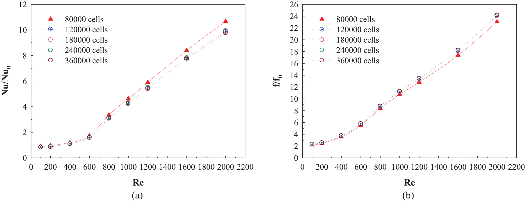
Grid independence of the HESC inserted with the WTR (HR = 0.20, PR = 1) for: (a) Nusselt number ratio and (b) friction factor ratio.
Numerical result
The numerical results of the HESC equipped with the WTR are separated into two parts; mechanisms in the HESC and performance assessment. The mechanisms in the HESC placed with the WTR are reported both flow and heat transfer profiles. The tangential velocity vector, temperature contour and local Nusselt number contour are plotted. The relation graphs between average Nusselt number ratio, average friction factor ratio and TEF with the Reynolds number are illustrated in the efficiency assessment part. The variations of the average Nusselt number ratio, average friction factor ratio, and TEF with the pitch spacing ratio are also concluded.
Mechanisms in the tested section
There are two parts in this topic; flow structure and heat transfer configuration. The heat transfer and flow profiles in the HESC placed with the WTR are an important part for the numerical investigation. The understanding of the mechanisms in the HESC can help to develop the heat transfer ability. The tangential velocity in transverse plane is selected to descript the flow configuration of the HESC inserted with the WTR. Figure 4(a) to (f) reports the tangential velocity in transverse planes of the HESC inserted with the WTR for HR = 0.05, 0.10, 0.15, 0.20, 0.25, and 0.30, respectively, at PR = 1 and Re = 800. As the figures, the insertion of the WTR in the HESC can perform the vortex flow in all examinations. The vortex flow is detected at the upper and lower parts near the channel walls. The strength of the vortex flow seems to be stronger and larger when enhancing the height ratio. The HESC inserted with the WTR at HR = 0.05 gives the weakest vortex flow, while the HR = 0.30 provides the opposite trend. The vortex flow disturbs the thermal boundary layer on the heat transfer surface that the reason for heat transfer ability and thermal efficiency improvements. The vortex flow in the HESC also helps a better fluid mixing between cold fluid at the center of the channel and hot fluid near the channel walls. The heat transfer ability in the HESC increases when increasing the strength of the flow.

Tangential velocity vector in y–z planes of the HESC inserted with the WTR at Re = 800 and PR = 1 for: (a) HR = 0.05, (b) HR = 0.10, (c) HR = 0.15, (d) HR = 0.20, (e) HR = 0.25, and (f) HR = 0.30.
The plots of the tangential velocity vector in y–z planes for the HESC inserted with the WTR are depicted as Figure 5(a) to (d) for PR = 0.5, 0.75, 1, and 1.25, respectively, at Re = 1000 and HR = 0.15. The vortex flow is found in all cases of the HESC placed with the WTR at various PR values. The vortex flow is detected at the upper and lower zones of all planes. At Re = 1000 and HR = 0.15, the PR = 0.75 and 1 performs the strongest of the vortex strength. The PR = 0.75 and 1 are an optimum pitch spacing of the WTR in the HESC. The optimum pitch distance will give the best for both heat transfer ability and thermal efficiency of the present model. The optimum pitch distance may bring the optimal length of the longitudinal flow which impinges on the heat transfer surface in the tested section. The impinging flow on the heat transfer surface is an important factor for the increment of the local Nusselt number due to the thermal boundary layer is disturbed.

Tangential velocity vector in y–z planes of the HESC inserted with the WTR at Re = 1000 and HR = 0.15 for: (a) PR = 0.5, (b) PR = 0.75, (c) PR = 1, and (d) PR = 1.25.
The temperature distribution in y–z planes of the HESC inserted with the WTR is plotted as Figure 6(a) to (f), respectively, for HR = 0.05, 0.10, 0.15, 0.20, 0.25, and 0.30 at Re = 800 and PR = 1. In general, the blue contour (cold fluid) is detected at the core of the channel, while the red contour (hot fluid) is detected near the channel walls for the smooth channel with no WTR. The insertion of the WTR in the HESC effects for the change of heat transfer profile. The disturbance of the thermal boundary layer on the heat transfer surface is detected in all cases. The slight disturbance of the thermal boundary layer is found in the HESC at HR = 0.05 and 0.10. The heat transfer profile in the testing section of HR = 0.05 and 0.10 is similarly as the smooth channel with no WTR. The level of the thermal boundary layer disturbance is found to enhance when augmenting the height ratio of the WTR. The better mixing of the fluid temperature is obviously found in the HESC when HR > 0.20 due to the enhancement of the vortex strength.

Temperature distributions in y–z planes of the HESC inserted with the WTR at Re = 800 and PR = 1 for: (a) HR = 0.05, (b) HR = 0.10, (c) HR = 0.15, (d) HR = 0.20, (e) HR = 0.25, and (f) HR = 0.30.
The temperature distribution in y–z planes of the HESC inserted with the WTR is shown as Figure 7(a) to (d) for PR = 0.5, 0.75, 1, and 1.25, respectively, at HR = 0.15 and Re = 1000. The best fluid mixing in the HESC is detected at PR = 0.75 and 1 because of the optimum length of the longitudinal vortex flow and impinging flow. This means that the WTR with PR = 0.75 and 1 will provide the best heat transfer ability. The HESC inserted with the WTR at PR = 0.5 performs the heat transfer structure as the smooth channel.

Temperature distributions in y–z planes of the HESC inserted with the WTR at Re = 1000 and HR = 0.15 for: (a) PR = 0.5, (b) PR = 0.75, (c) PR = 1, and (d) PR = 1.25.
Figure 8 reports the local Nusselt number distribution on the channel walls of the HESC inserted with the WTR at various HR values. The heat transfer behavior in the HESC inserted with the WTR is in similarly pattern in all HR values. As the figure, the HR = 0.30 gives the highest heat transfer ability, while the HR = 0.05 performs the reversed trend. The HR = 0.30 can produce the strongest vortex flow, therefore, the HR = 0.30 gives the highest heat transfer ability. The HR = 0.05 and 0.10 give slightly higher heat transfer coefficient than the plain channel with no WTR. The peak of heat transfer rate is detected at the sidewalls of the HESC and in front of the WTR regime (see Figure 9). The peak of heat transfer regime occurs due to the impingement of the fluid flow and thermal boundary layer disturbance on the heat transfer surface.

Nux contour of the HESC inserted with the WTR at Re = 800 and PR = 1 with various HR values.

Nux contour of the HESC inserted with the WTR at Re = 800 and HR = 0.15 with various PR values.
Figure 10 presents the local Nusselt number distribution on the channel walls of the HESC inserted with the WTR at various PR values. The profile of heat transfer in the HESC with various PR values is found to be in similar pattern. The greatest Nusselt number for the present investigation is detected at PR = 0.75 and 1 due to the optimum length of the longitudinal streamline flow and impinging flow, while the PR = 0.5 performs the opposite result.

Description of the heat transfer behavior in the HESC inserted with the WTR.
Performance assessment
Figure 11(a) to (d) plots the relation of the Nu/Nu0 and Re for the HESC inserted with the WTR for PR = 0.5, 0.75, 1, and 1.25, respectively. Generally, the Nu/Nu0 in the HESC equipped with WTR increases when augmenting the Reynolds number. The increment of the heat transfer ability is due to the generation of the vortex flow, impinging flow on the heat transfer surface and better fluid mixing. When the height ratio is increasing, the heat transfer ability is also enhancing. This is because the height ratio of the WTR has directly effect for the strength of the vortex flow in the HESC. For all pitch spacing ratios, the highest heat transfer coefficient in the HESC placed with the WTR is detected at HR = 0.30, while the lowest value is found at HR = 0.05. The augmentation of the Nusselt number in the HESC is obviously detected at high Reynolds number and height ratio (HR > 0.05). In the range investigates, the Nu/Nu0 in the HESC placed with the WTR is around 1.00–7.36, 1.00–11.30, 1.00–12.55, and 1.00–12.96, respectively, for PR = 0.5, 0.75, 1, and 1.25.

Nu/Nu0 versus Re for the HESC inserted with the WTR of: (a) PR = 0.5, (b) PR = 0.75, (c) PR = 1, and (d) PR = 1.25.
The relations between f/f0 and Reynolds number in the HESC placed with the WTR are illustrated as Figure 12(a) to (d), respectively, for PR = 0.5, 0.75, 1, and 1.25. In general, the f/f0 in the HESC placed with the WTR increases when augmenting the Reynolds number in all PR values. The air velocity has directly effect for the enhancement of the pressure loss in the HESC. The friction loss in the HESC also raises when enhancing the height of the WTR, especially, at high height ratio (HR > 0.15). The installation of the WTR in the HESC brings higher friction loss than the smooth channel with no WTR around 1.00–100.39, 1.00–109.09, 1.00–90.44, and 1.00–75.30 times, respectively, for PR = 0.5, 0.75, 1, and 1.25.

f/f0 versus Re for the HESC inserted with the WTR of: (a) PR = 0.5, (b) PR = 0.75, (c) PR = 1, and (d) PR = 1.25.
The thermal efficiency factor or TEF is opted to discuss the enhancement of heat transfer ability in the HESC inserted with the WTR at similar pumping power. Figure 13(a) to (d) plot the relations of the TEF with the Reynolds number in the HESC for PR = 0.5, 0.75, 1, and 1.25, respectively. The TEF of the smooth square channel with no WTR is equal to 1. In almost cases, the insertion of the WTR in the HESC leads to higher thermal efficiency factor than the plain section (TEF > 1). The maximum TEF in the HESC inserted with the WTR at PR = 0.5, 0.75, 1, and 1.25 is around 2.48, 3.32, 3.43, and 3.16, which is detected at HR = 0.15, 0.15, 0.20, and 0.15, respectively.

TEF vs Re for the HESC inserted with the WTR of: (a) PR = 0.5, (b) PR = 0.75, (c) PR = 1, and (d) PR = 1.25.
The plots between Nu/Nu0, f/f0 and TEF versus PR in the HESC equipped with the WTR are shown in Figure 14(a) to (c), respectively, at Re = 2000. The HESC with PR = 0.75 and 1 provides the highest heat transfer coefficient for HR = 0.05–0.25. For HR = 0.30, the best value of the Nusselt number in the HESC is found at PR = 1.25. The pressure loss in the HESC with the WTR is found to be in nearly value for HR = 0.05–0.15. When HR > 0.15, the highest friction loss in the HESC is found at PR = 0.75. For HR = 0.05, the TEF in the HESC is equivalent to the smooth channel with no WTR (TEF ≈ 1) for all PR values. The maximum TEF in the HESC placed with the WTR is detected at PR = 0.75, 0.75, 1, 1.25, and 1.25 at HR = 0.10, 0.15, 0.20, 0.25, and 0.30, respectively. Figure 15 plots the contour of TEF for the HESC inserted with the WTR at various HR and PR values for Re = 600–2000. The contour plot of TEF for the HESC inserted with WTR can help to select and design the parameters of the WTR.
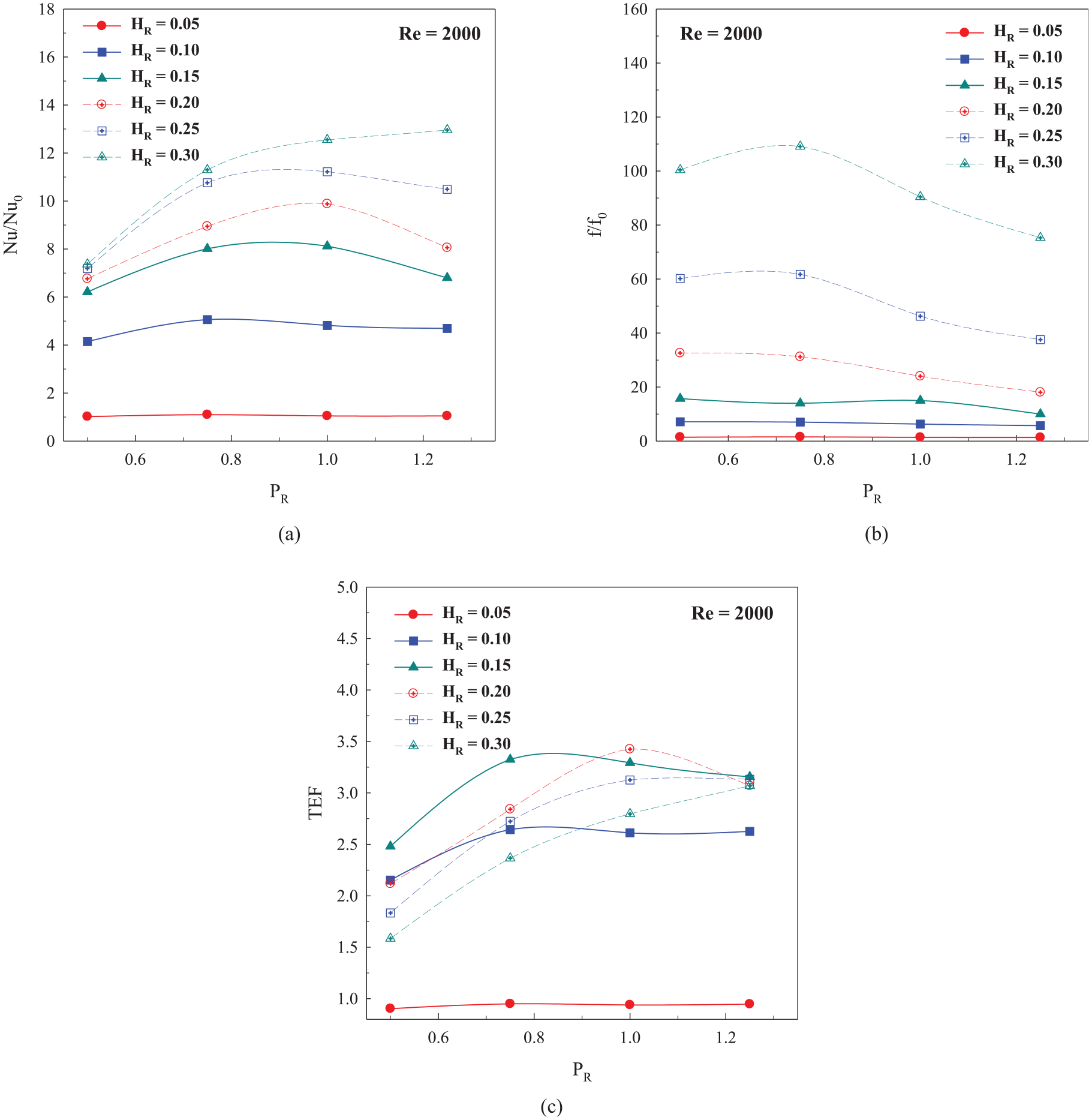
(a) Nu/Nu0 versus PR, (b) f/f0 versus PR, and (c) TEF versus PR.
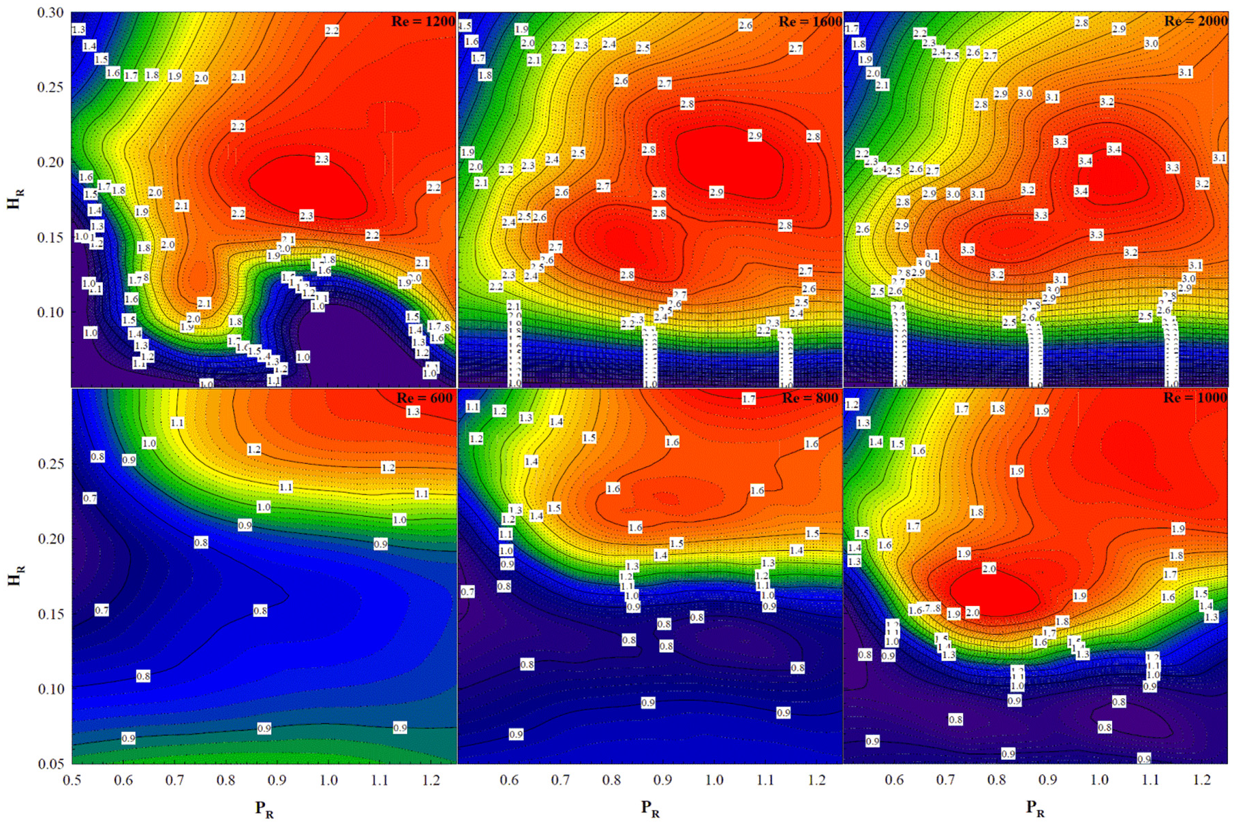
Contour of TEF with various PR and HR values at Re = 600–2000.
Conclusion
The numerical predictions on flow visualization and heat transfer profile in the HESC placed with the WTR are presented. The influences of WTR height to channel height (e/H or HR = 0.05–0.30), WTR pitch to channel height (P/H or PR = 0.5–1.25) and air velocity (Reynolds number, Re = 100–2000) on flow and heat transfer structures are considered. The mechanisms on both flow topology and heat transfer in the HESC are focused. The thermal efficiency assessments (Nusselt number, friction factor and thermal efficiency factor) in the HESC placed with the WTR are also concluded. The outcomes of the present investigation can conclude as follows;
The numerical investigation can help to describe the mechanisms both flow and heat transfer topologies in the HESC placed with the WTR. The knowledge of the flow and heat transfer visualizations is an important data for the improvement of the heat exchanger system. The numerical study also helps to save the cost when compared with the experimental investigation.
The installation of the WTR in the HESC brings higher heat transfer ability, friction loss and thermal efficiency than the baseline case. The WTR in the HESC can produce the vortex flow and impinging flow that the reason for the heat transfer augmentation. The vortex flow and impinging flow disturb the thermal boundary layer on the heat transfer surface (channel walls). The vortex flow and impinging flow also help a better fluid mixing between the cold fluid at the center of the channel and hot fluid near the channel walls. The better fluid mixing is also another cause for heat transfer improvement in the HESC.
The increments of the Reynolds number and WTR height effect for the enhancements of heat transfer ability in the HESC. This is because the augmentations of air velocity and WTR height have directly effect for the increment of the vortex strength. The heat transfer ability in the HESC increases due to the enhancement of the vortex strength. The pressure loss in the HESC also raises when enhancing the WTR height and Reynolds number.
The optimal pitch spacing ratio of the present investigation is around 0.75–1.00, when considered at the thermal efficiency factor. In addition, the greatest TEF in the HESC inserted with the WTR is around 3.43 at HR = 0.20, PR = 1, and Re = 2000.
The present results are compared with the previous works as depicted in Figure 16(a) to (c) for Nu/Nu0, f/f0 and TEF, respectively. Although, the highest heat transfer rate and thermal efficiency are not detected in the case of WTR, but the WTR can help to save the pressure loss in the heating system. The structure of the WTR has high stability when compared with the other types of the vortex generator. In addition, the WTR can create many cores of the vortex flow. The number of the vortex flow has directly effect for the distribution of the fluid temperature in the tested section.

Comparison with the previous works for: (a) Nu/Nu0 versus Re, (b) f/f0 versus Re, and (c) TEF versus Re.
Footnotes
Appendix
Acknowledgements
The authors would like to thank Assoc. Prof. Dr. Pongjet Promvonge for suggestions.
Handling Editor: James Baldwin
Declaration of conflicting interests
The author(s) declared no potential conflicts of interest with respect to the research, authorship, and/or publication of this article.
Funding
The author(s) disclosed receipt of the following financial support for the research, authorship, and/or publication of this article: This research was funded by King Mongkut’s University of Technology North Bangkok, Contract no. KMUTNB-64-KNOW-015.