
Abstract
A type of three-dimensional space bending flexible pneumatic arm employing axial elongation pneumatic artificial muscles was proposed. It was mainly composed of six pneumatic artificial muscles symmetrically distributed in parallel, and six artificial muscles were fixed 60° each other in space. The elastic skeleton was added among the arm to improve its rigidity and stability. Especially, the driving device of the arm was just the body of the arm. The arm has the advantages of simple structure, convenient manufacture, safety and flexibility, and it can achieve omnidirectional bending movement. According to the static characteristic and deformation of the arm, the kinematics model and the grasping force model of the arm were established. Further, the theoretical model was verified by experiments and then the relations between deforming properties, the working space, the grasping force and air pressure of the arm were obtained. The motion performance experiment of the arm was carried out in a laboratory environment. The experimental results show that the flexible arm has flexible movements, strong adaptive ability, simple control, and certain load capacity when bending.
Keywords
Introduction
With the increasing demand for robot technology, traditional rigid robots are difficult to satisfy people’s needs because of their complex structure, poor safety, and adaptability. 1 Compared to conventional rigid robots, flexible robots exhibit more advantages in terms of flexibility, lightweight, adaptability, and safety, making up for the shortcomings of rigid robots.2,3 Therefore, flexible robots have broad potential application prospects in physical rehabilitation, sophisticated environment detection, and fragile objects operation.4–7
In recent years, with the development of 3D printing technology8,9 and the development of applied intelligent soft materials have much promoted the development of flexible robots. 10 Based on the development of flexible robots at home and abroad, the driving method of flexible robots mainly includes rope, pneumatic artificial muscles, dielectric actuated polymers, and so on. 11 Pneumatic driving mainly adopts different cavity structure designs. It makes the robot deform or move by changing the pressure of the air in the cavity, which is the most widely used driving mode at present. The most typical flexible robot is PMA, designed by American physician McKibben in the 1950s. 12 Subsequently, PMA has been widely studied and applied to the design of various robots. 13 After decades of development, a variety of new structural forms of actuators have been proposed. Among them, actuators with three-dimensional space movement have been widely concerned by scholars at home and abroad. As early as the 1980s, Professor Suzumori of Japan developed the first three-chamber driven FMA, which were assembled to multi-fingers. 14 Zhang et al. 15 designed a novel mechatronics-embedded soft module with an air supply sharing function. The actuator has the good bending ability and solves the tube drag problem of soft modular robots. Mosadegh et al. 16 analyzed the pneumatic actuator by the finite element method and obtained the relationship between the bending angle and the air pressure of the actuator. Marchese and Rus 17 developed a continuous arm with a total length of 500 mm and a mass of 0.6 kg, which can realize bending in any direction and has strong adaptability to the environment. Xie 18 used the finite element analysis software to optimize the design of the 3D software actuator. According to the simulation optimization conclusion, the 3D software arm prototype was manufactured, which realized multiple degrees of the freedom movement in space and the grasping of various objects underwater. Still, the load was small, and the pressure resistance is weak because there is no external constraint. In 2014, the German Festo company 19 developed a pneumatic elephant trunk arm with a length of 600 mm and a maximum diameter of 20 mm. Through the compression and inflation of an airbag, it expands and can reach a spherical workspace with a maximum radius of 0.6 m. Still, its load capacity and stability is insufficient. The University of Pennsylvania 20 has successively developed the OctArm series of elephant-like arms, and a large number of related experiments have been done in the real environment. Giannaccini et al. 21 developed a novel variable stiffness soft arm consisting of elongated and contractile pneumatic muscles. However, the stiffness adjustment range of the arm is small, and when two muscles of equal length work at the same time, they are mutual impedance, which affects the deformation of muscles. Chen et al. 22 developed a continuous robot made of silicone rubber, with six channels evenly distributed on the inner circumference, which can realize bending in any direction. Trivedi and Rahn 23 designed a kind of flexible arm with a large carrying capacity by using pneumatic artificial muscle. The arm can carry a weight of 110 pounds, but the movement form is single, and the control system is enormous. In summary, the flexible pneumatic arms are mostly made of soft materials or flexible materials. Their stretchable bodies can deform and absorb energy during operation, making them have better safety and flexibility. However, flexible arms have two main disadvantages: one is that the volume of the air chamber will change with the increase of air pressure. Without the addition of a restrictive layer, irregular bubbling will occur, which will affect the movement of the arm in a non-structural environment. The other is that the nonlinear principle between deformation and driving force, which makes the accurate real-time control of the arm more difficult.
In the three-dimensional space actuator or flexible arm developed by predecessors, most of the arms are relatively independent of the joint body and the driving device, and the flexibility of movement and driving mostly depends on compliance control. To solve the problems of insufficient flexibility, poor safety, and bearing capacity of the arm, a type of three-dimensional space bending flexible pneumatic arm is developed, and the arm can improve the motion adaptability through the deformation of composite elastomer structure. The core idea of the design is to construct a flexible arm with elastomer as the main body to realize the adaptability and flexibility. Pneumatic artificial muscle is adopted to solve the problems of flexible drive and buffering avoidance of the arm. The integrated composite structure of pneumatic muscles and a flexible skeleton is adopted to solve the problems of compact and lightweight of the arm. It has high academic value and practical significance.
Structure and function of flexible arm
The three-dimensional model of the flexible pneumatic arm (Figure 1(a)). Six axial elongation pneumatic muscles (latex tube, constraint rings, and the plug form a seal cavity called artificial muscle) of the same size are set uniformly in the circumferential direction and generate motions by cooperating. Spring and other elastic elements located in the middle of the arm, which can not only support and connect the arm, but also improve the rigidity and elastic recovery ability of the arm, ensuring the realization of the movement function. The flexible arm is capable of two-axis bending and elongate in the axial direction when supplied the air pressure, which makes the arm have three degrees of freedom. The six pneumatic muscles are 24 mm away from the center and uniformly distributed at 60° circumference (Figure 1(b)). As shown in Figure 1(c), the material of the constraint ring is ABS plastic, which makes the arm very light. Its principal function is to limit the radial expansion of the latex tube and ensure that the muscles are equidistant from the center. The main structural dimensions and material parameters of the arm are shown in Table 1.

Structure of flexible arm: (a) three-dimensional model, (b) cross-sectional dimensions (dotted lines show three control channels), (c) constraint ring, and (d) increasing/decreasing pressure of axial elongation pneumatic artificial muscle.
Geometric and material characteristics of the flexible arm.

Figure 1(d) shows the working process of axial elongation pneumatic artificial muscle. When compressed air is injected, the inner wall of the artificial muscle is compressed or expanded. Due to the existence of external constraint rings, the radial expansion of the artificial muscle will be limited. The amount of axial deformation will be maximized so that the energy conversion efficiency can be improved. When the air pressure is removed, the artificial muscle will return to its original state under the action of its own elasticity.
When compressed air of different pressures is introduced into the six pneumatic muscles, the arm will undergo a combined deformation movement of elongation and bending. Therefore, the multi-degree of freedom movement of the arm in three-dimensional space can be realized by controlling the air pressure of each muscle. To facilitate the control, three control channels are selected, and each control channel controls two adjacent artificial muscles (Figure 1(b)). Compared to three muscles, the design results in muscles located at a larger radius, corresponding to higher stiffness and load capacity. Under the same conditions, two muscles driven in parallel can make the arm get more bending angle and driving force.
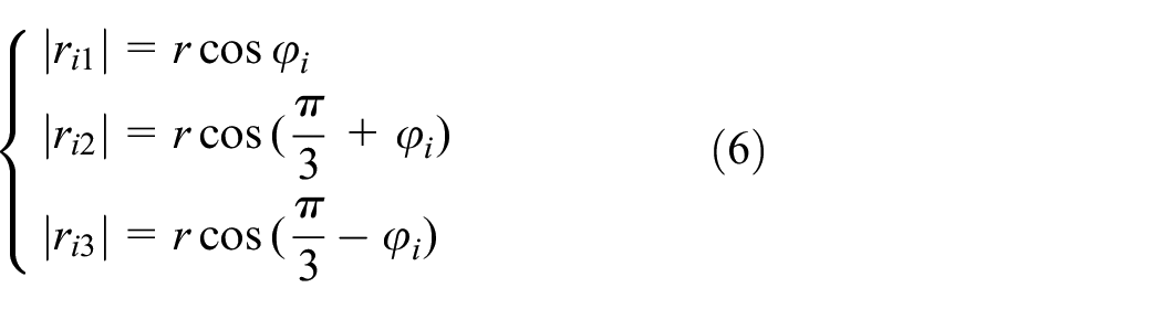
The flexible arm bends like an arc when bending, which has the elastic bending characteristics of shaftless and multi-hinge (Figure 2(a)). The data points of the curved contour on the central axis of the arm under different pressure of two control channels were circularly fitted, and the results were shown in Figure 2(b).
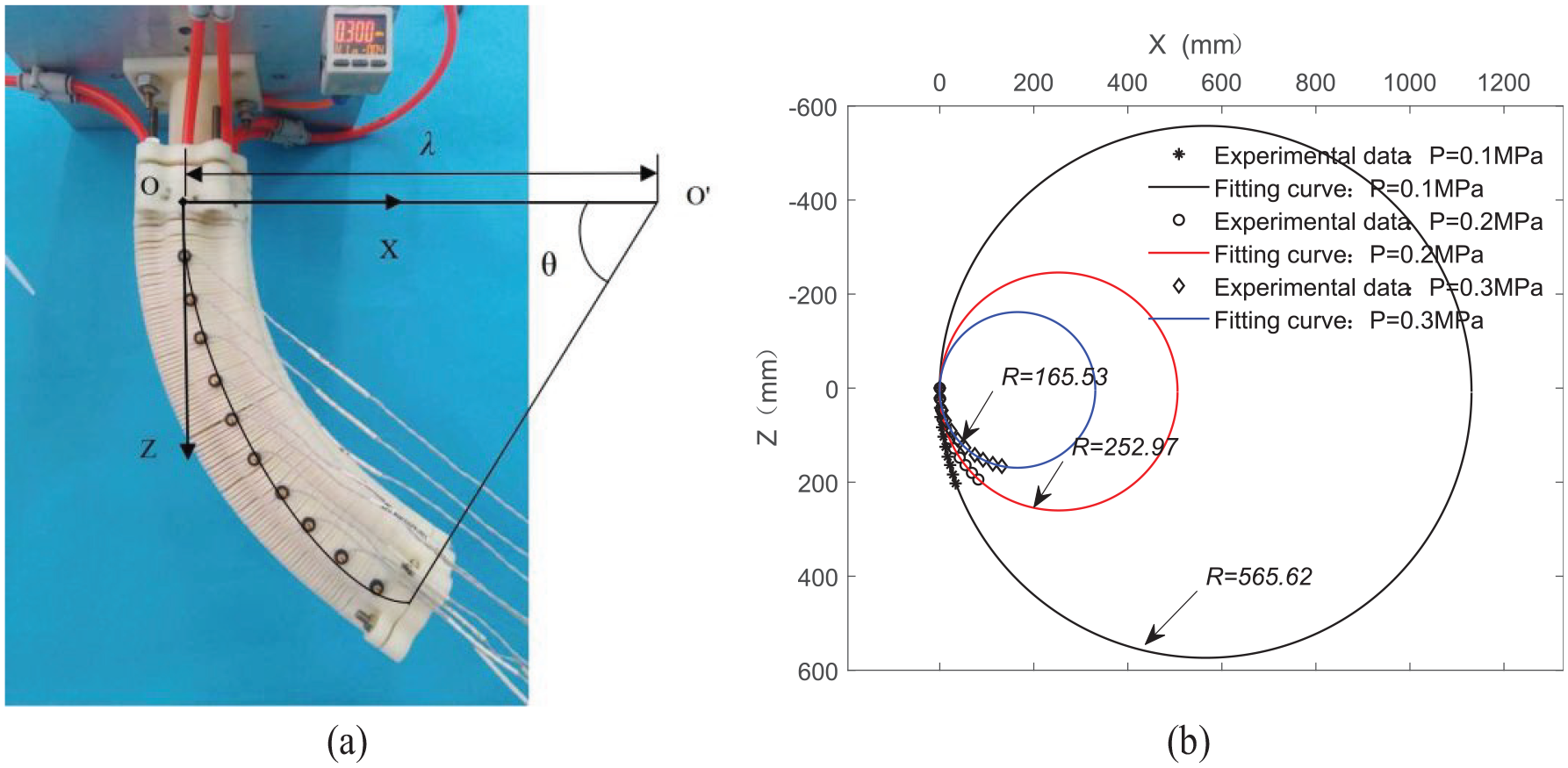
Bending the arc of the flexible arm: (a) schematic diagram of bending and (b) bending fitting curve.
By comparing the distance from the data point on the center axis of the arm to the center of the circle and the radius of the fitted circle, the errors are 0.49%, 1.29%, and 2.56%, respectively. The comparison results show that the arm was in an arc shape when it was bent.
Due to the nonlinearity of the materials, it complex to obtain accurate static theoretical models of the arm, so we finish this task via experiments. According to the experimental data, the relationship between elongation, bending angle of the arm and air pressure were obtained by the polynomial fitting method. The empirical formula is as follows:

Where
Kinematic analysis of flexible arm under no load
The pose representation of kinematics modeling
According to the layout of the artificial muscle in the flexible arm and its deformation law of arc bending, its position can be expressed by three parameters, the radius of the bending curve

Kinematics modeling: (a) establishment of the coordinate system, (b) the global view of modeling, (c) general kinematics model for a segment, and (d) distance from muscle to neutral layer.
To accurately express the spatial position of the flexible arm, it is divided into a bending section and a rigid section and multiple characteristic points are taken in the deformation zone to describe the deformation (Figure 3(a)). The base coordinate system
The spatial position of the i-section of the flexible arm (Figure 3(c)). Based on the piecewise constant curvature theory, 24 the general formula of the transformation matrix of the adjacent feature points on the arm bending section is as follows:

The transformation matrix of the rigid section could be written as follows easily:

Where
The coordinate transformation of the tip center of the flexible arm relative to the base coordinate system is as follows:

When we want to know the exact coordinate of the tip on the flexible arm in the base coordinate system, post-multiply a vector [0;0;0;1] which describes the tip’s location in
The destination of our transformation is to represent the location parameter (

Where
The centers of the three control channels form an equilateral triangle. According to the geometric relationship, the distance between the muscle of each control channel and the neutral layer can be obtained as follows:
Where
According to the calculation formula of arc length, the calculation formula of muscle length in the i-section are as follows:

By simplifying equation (7), the intermediate variables (

According to equations (4) and (8), the corresponding relationship between the elongation of the artificial muscle and the position of the arm in space can be established.
Kinematics simulation under no load
The trajectory and workspace of the arm can be obtained by substituting equation (1) into the kinematics equation of the arm. Figure 4 shows the movement trajectory of the arm in the X-Z plane under different air pressures. According to the fitting formula of arm elongation, it can be known that the elongation rate can reach 45.2% at 0.34 MPa air pressure, from which the spatial distribution of the center of the arm end can be determined, as shown in Figure 5. By changing the length of the artificial muscle, the arm can be bent in any direction with the origin of the base coordinate system as the center, as shown in Figure 6, which also verifies the correctness of the kinematics model.

Relationship curves between the deformation of the arm and air pressure ( indicates that the airflow valve is open): (a) muscle ventilation in control channel I and (b) muscles ventilation in control channels II and III.

Simulations on the workspace of the flexible arm.

The spatial bending form of the flexible arm.
It can be seen from Figure 4 that the amplitude of arm bending deformation increases with the increase of air pressure.
It can be seen from Figure 5 that the workspace clearly shows three-dimensional motion accessible to the flexible robotic arm, and the maximum bending angle in one direction is more than 90°.
Analysis of grasping force of flexible arm
The inner wall of the artificial muscle was compressed and expanded after being introduced with compressed air. The cross-sectional area of the deformed lumen can be expressed as follows 25 :

Where
According to the structure and deformation characteristics of the flexible arm, its elongation could be written as follows obviously:
Where
Under the action of compressed air, the output force generated by the arm is shown as follows:
Where
Figure 7 describes the analysis process of grasping force, and the three positions of the arm in the process of its deflection. As shown in Figure 7(a), d is defined as an object offset representing the distance between the initial position of the arm and the contact point with the grasped object along the X-direction. In the process of modeling, the grasped object is assumed to be a rigid cuboid. Figure 7(b) describes the specific force analysis at position ②.
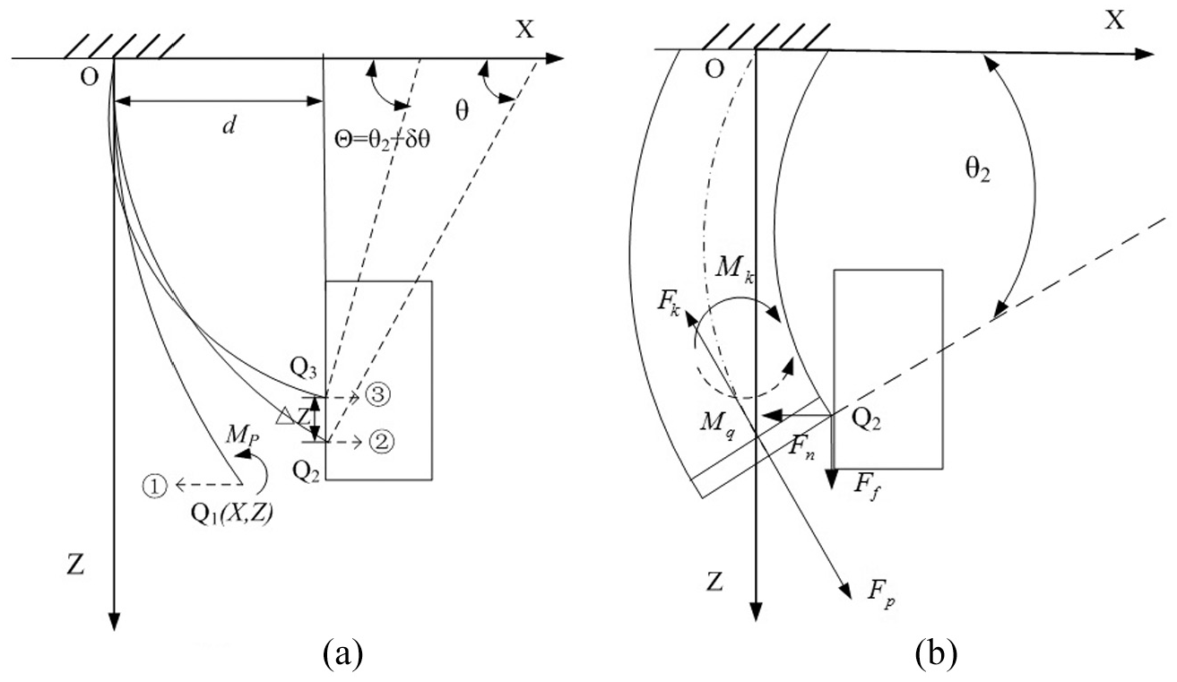
Analysis of the grasping force model of the flexible arm: (a) schematic describing the process of deflection of the arm and (b) specific force analysis from position ②.
As shown in Figure 7, grasping force and friction force are generated after the arm contacts with the object, and the bending grasping force is equal to the sum of the grasping force and friction force. According to the force balance:

Where
With the increase of air pressure, the flexible arm moves from position 2 to position 3, and the arm will continue to deform and generate an additional angle

Where
The driving torque can be written as follows:

Where
The deformation of the arm is reduced due to the obstruction of the contact object. Compared with the free deformation, the elongation and bending angle are

Where
After the restricted deformation, the internal friction of the arm due to its protrusion is

When the air pressure is increased by

Substituting equations (14) to (17) into equation (13), the grasping force of the arm can be deduced as follows:

Experimental study on the statics of the flexible arm
The experimental system of arm statics (Figure 8). In addition to the arm body and air pressure control system, this experimental system also added a data acquisition system. An inertial sensor module (model: MPU6050) is installed on the top of the arm to measure its spatial attitude. The deformation of the flexible arm can be measured using the three-dimensional motion measurement system (model: Optotrak Certus TM). The relationship between grasping force and air pressure was measured by a force transducer (model: HF-100). The air pressure sensor (model: SMC-PSE560) can measure the air pressure of the artificial muscle in the flexible arm.

The experimental system of the flexible arm statics.
Axial elongation of flexible arm
The theoretical data of elongation can be obtained by substituting the structural dimensions and corresponding physical parameters of the arm into equation (10). Figure 9 shows the comparison between theoretical curves and experimental data.

Comparison curve of theory and experiment of the elongation.
From the comparison between the theoretical data and the experimental data, the two trends are the same, and the coincidence degree is high, which shows that the theoretical formula can truly reflect the deformation law. The elongation of the arm increases with the increase of the air pressure. Because the cross-sectional area of the inner cavity changes significantly and the driving force is inconsistent during the muscle deformation, the elongation of the arm changes nonlinearly.
The deflection angle of the flexible arm
Figure 10 shows the various curves of the deflection angle of the arm with air pressure. From the comparison between the theoretical data and the experimental data, the two trends are consistent and in good agreement, indicating that the theoretical formula can truly reflect the changing law of the deflection angle. When the air pressure of PI and PII remains constant, the deflection angle of the arm increases or decreases with the increase of the air pressure PIII.

Variation curves of the deflection angle.
It can be seen from Figure 11 the arm can be controlled in any direction within the range of 0°–360° by adjusting the air pressure of the muscles in the other two control channels when the air pressure of the muscles in one control channel is constant.

Variation surfaces of the deflection angle with air pressure: (a) PI = 0 MPa, (b) PI = 0.1 MPa, (c) PI = 0.2 MPa, and (d) PI = 0.3 MPa.
The bending angle of the flexible arm
Figure 12 shows the various curves of the bending angle of the arm with air pressure. From the comparison between the theoretical data and the experimental data, the two trends are consistent and in good agreement, verifying the correctness of the theoretical model. The first half of the theoretical curve is larger than the experimental data due to two reasons. The primary reason is that there is a certain gap between the binding ring and the latex tube, and the second reason is the manufacturing error in the manufacturing process of the arm.

Various curves of bending angle of the flexible arm.
By adjusting the air pressure of the muscles in the three control channels, not only can the arms be bent in different directions, but also the bending angle of the arms can be changed. Figure 13 shows the various surfaces of bending angle of the flexible arm with air pressure.
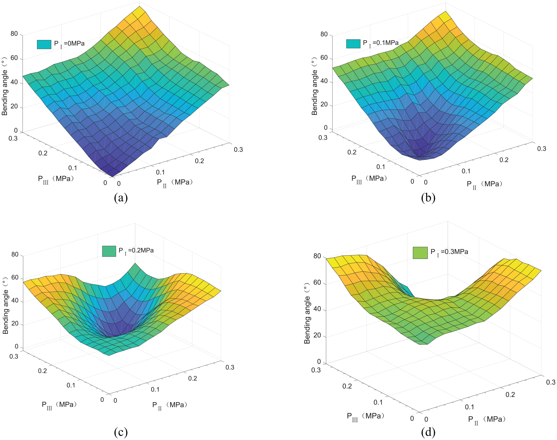
Various surfaces of the bending angle with air pressure: (a) PI = 0 MPa, (b) PI = 0.1 MPa, (c) PI = 0.2 MPa, and (d) PI = 0.3 MPa.
As shown in Figure 13, when the pressure of PI remains unchanged, the bending angle gradually increases and has a certain nonlinear with the increase of pressure of PII and PIII, and the bending angle varies from 0°to 79.7°. When PI = PII = PIII, the bending angle of the flexible arm is the smallest. At this time, the arm only elongates without bending.
The grasping force of the flexible arm
The curve of the grasping force changing with the air pressure after the arm contacts the target at different bending positions can be obtained using the experimental device (Figure 8). When the arm is limited at the starting point of bending, the curve of the grasping force changes with the pressure is shown in Figure 14. By comparing the theoretical data with the experimental data, it can be obtained that the coordination coefficient of bending deformation driven by the I control channel is 0.25, and the coordination coefficient of the bending deformation driven by II and III control channels is 0.1. Figure 15 shows the comparison curve of grasping force with air pressure when the arm is clamped to different restrained planes.

Comparison curve of theory and experimental of the grasping force.
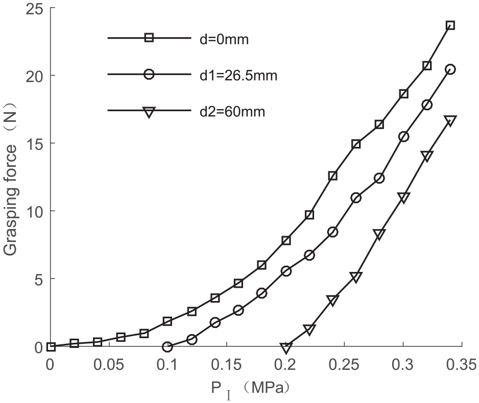
Comparison curve of grasping force in different restrained planes.
It can be seen from Figure 14 that with the increase of air pressure, the grasping force of the flexible arm increases nonlinearly. The maximum grasping force of the arm is 49.25 N when the air pressure is 0.34 MPa. As can be seen from Figure 15, the clamping capacity of the arm to different restrained planes is different. The basic rule is that the farther the restrained plane is from the starting point of arm bending, the weaker the acting ability of the arm is.
According to the observation from the experiment, when the arm is clamped on the restricted surface driven by air pressure, the deformation of the arm will occur and increase with the increase of air pressure (Figure 16). Figure 17 shows the deformation form of the central axis of the arm after its bending is limited.

Morphological changes of the arm after contact with the restrained surface.
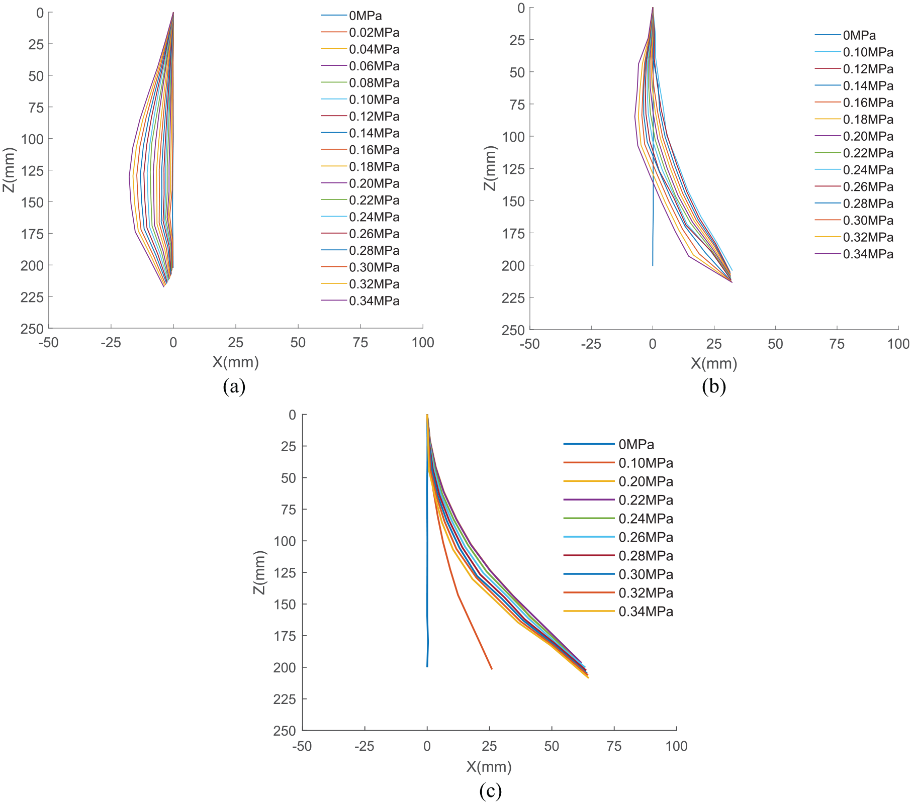
Relationship between axial deformation and air pressure of arm in different restrained plane: (a) d = 0 mm, (b) d = 26.5 mm, and (c) d = 60 mm.
As can be seen from Figure 17, with the increase of air pressure, the centerline of the arm elongates and bulges. Among them, the bulging phenomenon at the initial bending position (d = 0 mm) is the most obvious, and the shape line no longer conforms to the arc curve during free bending. The main reason is that the deformation of the arm is caused by the combined effect of air pressure and the reaction force of the contact point.
Experimental study on motion performance of the flexible arm
To facilitate grasping objects, the arm is connected with the four-finger manipulator in series. 26 At the same time, in order to increase the working space of the flexible arm and improve its motion ability, the flexible arm is fixed on a base platform that can move along the X-axis and Z-axis, as shown in Figure 18.

Grasping experimental platform.
An embedded air pressure control system based on digital PID algorithm is designed, and LPC2210 is used as the core processor to realize the real-time control of the flexible arm (Figure 19). The X and Z slides are driven by two stepper motors, and the air pressure of each muscle of the flexible arm is controlled by an electric proportional valve group (model: ITV0050-3BS). According to the position of the target object, the controller sends out a control command and controls the motor to drive the sliding table through the stepper motor driver. Adjusting the voltage of the proportional valves 1, 2, and 3 in the air pressure control system to control the air pressure in the muscles to achieve three-dimensional movement of the arm. The proportional valves 4, 5, 6, and 7 are used to control the manipulator to achieve grasping.

Control system diagram of the flexible arm.
Experiment on no-load performance of the flexible arm
Under the control of the air pressure system, a multi-degree of the freedom movement in the space of the arm can be achieved through coordination between muscles. As can be seen from Figure 20, the flexible arm has good flexibility, and can bend in any direction within 360° of the XY plane.

Diagrams of movement of the flexible arm: (a) main view and (b) top view.
Experiment on load performance of the flexible arm
The lateral load capacity of the flexible arm is the key to complete various operating functions, which directly affects the load performance of the arm. As shown in Figure 21, to test the lateral load capacity of the arm, a water bottle with a diameter of 66 mm was selected as the container, and the height of the arm under different weights was tested by injecting water into the bottle. Figure 22 shows the height that the flexible arm can reach under different loads.

Load movement of the flexible arm.

Height of the flexible arm with different loads.
As can be seen from Figure 22, the load height of flexible arm decreases with the increase of the weight. Under the same weight, the load height is also increased with the increase of air pressure. When the weight is 650 g, the end of the arm is raised by 9 mm and 34 mm at 0.2 MPa and 0.3 MPa, respectively.
Experiment study on grasping objects of different shapes
As shown in Figure 23, the flexible arm can complete the functions of grasping, moving and lowering the object. Taking grasping a small ball as an example, the specific process is divided into six steps as follow:
According to the position of the ball, the flexible arm moves to the appropriate position and adjusts its posture to make the ball in its wrapping area.
Continue to increase the corresponding finger pressure to make it hold the ball steadily.
Adjust the Z-direction sliding table to increase the height of the ball.
Move the flexible arm over the cup.
Adjust the Z-direction slide table to reduce the height of the ball to a suitable position.
Release the air pressure of the manipulator and put the ball into the cup accurately.
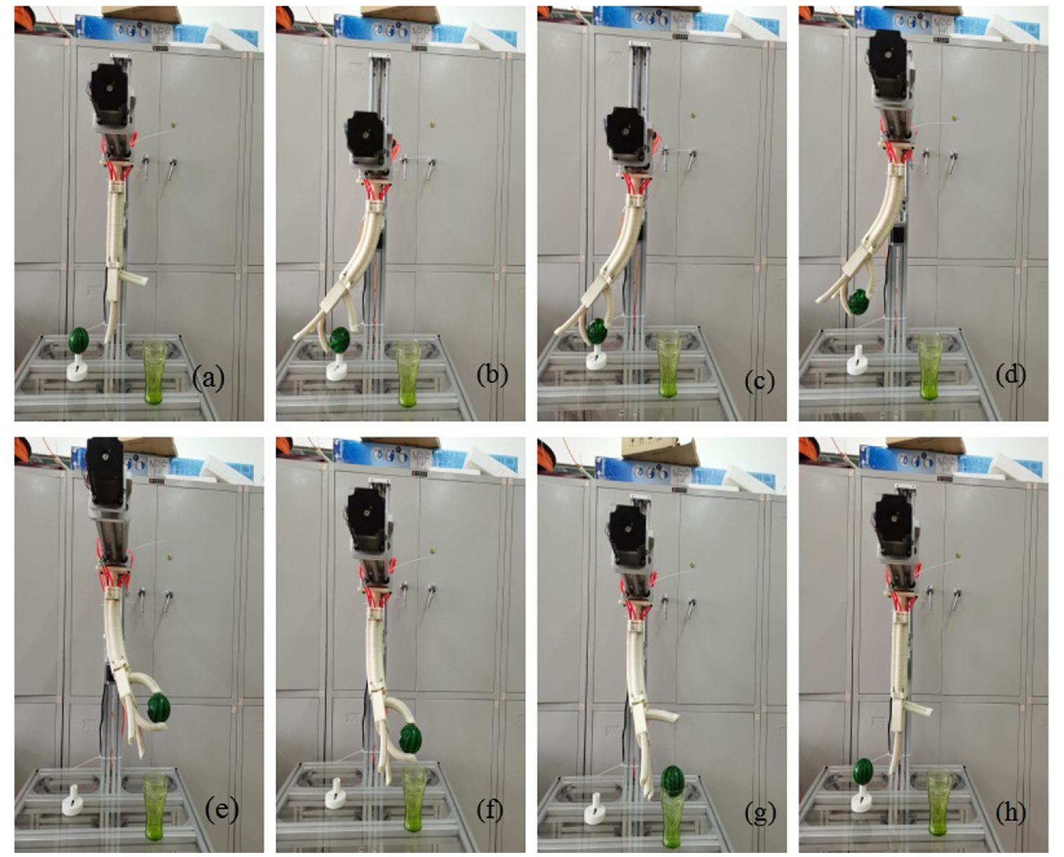
The process of grasping the object: (a) the initial position, (b) ready to grasp, (c) grasp the ball, (d) lift the ball, (e) move the ball to the cup, (f) lower the ball, (g) release the ball, and (h) reset.
To further test the adaptive grasping ability of the flexible arm to objects of different shapes, ordinary objects in daily life are selected for grasping, as shown in Figure 24. The parameters of the grasped object in the experiment are shown in Table 2. In Table 2, D is the diameter of the object, L is the length of the object, W is the width of the object, and H is the height of the object.

Grasping of the flexible arm.
Parameters of the grasped object.

It can be seen from Figure 24 that the flexible arm has good adaptability and can grasp all kinds of objects with an irregular shape.
Conclusion
A type of three-dimensional space bending flexible pneumatic arm is designed by using axial elongation pneumatic artificial muscles and flexible skeleton integrated composite structure. When the compressed air is injected, the arm is elastic deformation, which can achieve elongation and two-axis bending. The conclusions can be summarized as follows:
The kinematics model of the flexible arm was established, and the correctness of the model was verified. The deformation, workspace and motion posture of the flexible arm under different air pressures were simulated and analyzed. The simulation results show that the flexible arm can achieve three-dimensional movement in space, and the maximum bending angle exceeds 90°.
The theoretical model of the deformation of the flexible arm was established, and the variation rules of its axial elongation, bending direction, bending angle and air pressure were obtained, and the relevant experimental verification is carried out. The experimental results show that the flexible arm can achieve axial elongation and bend in any direction in space, and the elongation and bending angle of the flexible arm are directly proportional to the air pressure. When the air pressure is 0.3 4MPa, the axial elongation can reach 45.2%, the bending angle can reach 96.4° and the deflection angle range is 0°–360°.
The grasping force model of the flexible arm is established, and the variation rules of the grasping force and air pressure of the arm were obtained. The experimental results show the grasping force of the arm on the object is positively related to the air pressure. Besides, the grasping force is also related to the position of the clamping point. The basic rule is that the closer the clamping point is to the starting point of arm bending, the greater the clamping ability of the arm is. Among them, the grasping force on the starting point of arm bending is the strongest, reaching 49.25 N.
The motion performance experiment of the flexible arm was carried out on the control system. The results of no-load and grasping experiments verify that the flexible arm has good flexibility and adaptability. The load experiment shows that the load capacity of the flexible arm is proportional to the air pressure.
This new flexible arm exhibits the advantages of large grasping force, low cost, lightweight, and ease of fabrication and repair and is expected to be used in a variety of applications such as service industry, packaging automation, and agriculture harvesting. In the future, visual sensors and more advanced adaptive control algorithm will be used to analyze the effectiveness of the kinematic model of the flexible arm to reduce the influence of the arm’s own weight and external loads on the robotic arm.
Footnotes
Handling Editor: James Baldwin
Declaration of conflicting interests
The author(s) declared no potential conflicts of interest with respect to the research, authorship, and/or publication of this article.
Funding
The author(s) disclosed receipt of the following financial support for the research, authorship, and/or publication of this article: The authors would like to thank the National Natural Science Foundation of China No. NSFC 51275004, 51206011, and U1937201, Jilin Province Science and Technology Development Program of Jilin Province No. 20200301040RQ and 20180201050GX, Project of Education Department of Jilin Province No. JJKH20190541KJ and JJKH20190640KJ.